1
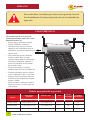
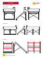
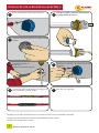
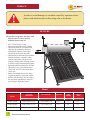
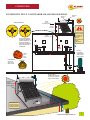
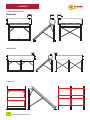
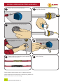
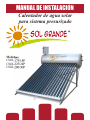
MANUAL DE INSTALACIÓN
Calentador de agua solar
para sistema presurizado
Modelos:
CSOL175/18P
CSOL225/24P
CSOL280/30P
PREFACIO
Para evitar daños o accidentes por errores en la operación, favor de
leer detenidamente las instrucciones antes de usar un calentador de
agua solar.
CARACTERÍSTICAS
Este producto puede de ser usado en
sistemas presurizados, puede usarse casas
habitación, hoteles, etc.
• Seguro, limpio, ahorrador de energía,
protege el ambiente, económico.
• Alta absorción: Los tubos evacuados
adoptan las más avanzadas técnicas de
manufactura, esto mejora la absorción del
espectro solar.
• Alto aislamiento, grueso aislamiento
térmico de poliuretano, su cuerpo
espumoso soporta todas las características
de presión y temperatura, mantiene el
proceso de obtención de calor asilado
preservando el calor.
• El interior del tanque y la tubería
entrada/salida es de: Acero inoxidable 304
• El material del tanque exterior: Hoja de
Acero recubierta de Al-ZN / Color acero.
• Soportes: Hoja Galvanizada o Aleación
de aluminio, para una apariencia elegante,
robusta y durable.
• Sellos de Caucho y anillos de Caucho al
silicón, no tóxicos y sin sabor, para una
vida útil larga.
Modelos para aplicación a gravedad
Dimensiones
generales
Tubo de vacío
Area
Volumen
del tanque
Cantidad
de duchazos
L x W x H (mm)
D x L x N (mm)
m2
L
Veces por día
CSOL175/18P
1820 x 1662 x 1752
¢ 58 x 1800 x 18
2.33
175
4-5
CSOL225/24P
2300 x 1662 x 1752
¢ 58 x 1800 x 24
3.11
225
5-6
CSOL280/30P
2780 x 1662 x 1752
¢ 58 x 1800 x 30
4.16
280
7-9
Modelo
2
MANUAL DE INSTALACIÓN
CONEXIONES
CONEXIONES DE UN CALENTADOR SOLAR PARA SISTEMA PRESURIZADO
Tubería de
venteo
Válvula de
llenado
Válvula
de alivio
Presión/temperatura
Válvula
antirretorno
Sistema
presurizador
sugerido para
elevar el agua
hasta el techo
El equipo debe
instalarse de tal manera
de no recibir sombra en
ningun momento del día.
La tubería de
retorno
preferentemente
debe de aislarse.
El techo debe de
soportar el peso del
equipo con el tanque
completamente lleno.
El equipo
siempre debe de
estar orientado
hacia el Sur.
MANUAL DE INSTALACIÓN
3
ENSAMBLE
Soporte: Aleación de aluminio
CSOL175/18G
CSOL225/24G
3. Reflector
Reflector
Reflector
4
MANUAL DE INSTALACIÓN
INSTALACIÓN
1.
2.
3.
4.
Antes de ensamblar el calentador solar, asegúrese que todos los componentes vienen en el empaque (Vea el Apéndice)
Ensamble el soporte de acuerdo al diagrama.
Este sistema debe de ser instalado en una superficie horizontal. No está diseñado para montarlo en una pared.
Desempaque los tubos evacuados, coloque el sello negro en la parte superior del tubo. Lubrique la parte superior
con agua jabonosa para una mejor inserción del sello.
5. Coloque 2 o 3 ánodos en los tubos cercanos de la salida de agua caliente.
6. Inserte el tubo evacuado en la abertura del tanque.
7. Cuidadosamente empuje el tubo a través del sello de silicón en el tanque, dando vueltas continuamente hasta que
la parte superior del tubo hasta librar el soporte del tubo. Entonces suavemente baje el tubo dentro del soporte inferior.
Tenga cuidado de no descolocar el sello cuando ajuste el tubo.
8. Conecte la tubería y accesorios de acuerdo al diagrama de conexión.
9. Aislé todas las tuberías y accesorios del tanque para asegurar poca perdida de calor.
10. Instale una válvula mezcladora en la salida del agua caliente como medida de precaución.
11. Cuando termine la instalación, llene de agua el tanque, revise que no haya fugas en el sistema, conecte los tubos y
el colector, las tuberías de entrada y salida, compruebe que las tuberías de venteo estén libres, compruebe que el
colector y el soporte estén bien colocadas y que el equipo este estable cobre el techo.
ATENCIÓN EN LA INSTALACIÓN
•
•
•
Los instaladores trabajaran en el techo, asegúrese de tomar las precauciones de seguridad.
Revise que el edificio tiene la capacidad de soportar el peso del sistema lleno de agua. La instalación no debe de
romper la estructura del edificio y evitar que la reflexión del colector de contra otro edificio del vecindario.
El calentador solar debe de dar hacia el sol, orientándolo hacia el sur. Garantizando la máxima área del colector
recibiendo la luz del día.
MANUAL DE INSTALACIÓN
5
INSTALACIÓN DE AL RESISTENCIA ELÉCTRICA
1
Retire la cubierta de la Resistencia eléctrica.
2
Coloque el sello de caucho en la Resistencia
y coloque teflón en la rosca.
3
Atornille la Resistencia eléctrica en su lugar usando
la mano.
4
Atornille firmemente la
Resistencia
usando la herramienta especial.
5
Atornille los 5 tornillos a la cubierta con el sello
de caucho.
6
Conecte los cables de alimentación, asegúrese de
usar aislamiento a prueba de agua.
7
Revisiones de seguridad.
Asegúrese que el cable de alimentación a la resistencia eléctrica esta correctamente conectado.
Asegúrese que la resistencia eléctrica esta apropiadamente puesta a tierra.
Asegúrese que no haya corto circuito.
6
MANUAL DE INSTALACIÓN
REGULACIONES DE SEGURIDAD
Los controles deben de instalarse en un lugar donde los niños no puedan tocarlos para prevenir algún peligro por jugar
con ellos.
Escoja productos regulados, si usted desea usar la resistencia eléctrica o combinarla con un calentador eléctrico de agua.
Asegúrese que la protección de tierra este bien instalada y el tanque este lleno de agua. Calentar sin agua está estrictamente
prohibido. Corte la energía eléctrica cuando se bañe.
Mantenga el tanque lleno durante tifones, suspenda su uso durante tormentas eléctricas.
Mantenga las ventilas de aire siempre abiertas, no las bloquee. La máxima longitud del tubo de venteo es de 30cm
INSTRUCCIONES DE OPERACIÓN
1.
2.
3.
4.
5.
6.
7.
8.
9.
Llene con agua fría los tubos evacuados por primera vez.
Si no se usa el equipo en invierno durante periodos de clima congelante favor de drenar el tanque, para evitar que
se congelen las tuberías.
Regule la temperatura de la válvula de acuerdo a la estación del año y la presión del agua para tener una temperatura
agradable, a fin de evitar quemaduras por agua caliente.
Después de usar agua caliente en días muy soleados o no usara agua caliente por algunos días soleados, evite cargar
agua inmediatamente o cargue agua después de 2 horas de que no haya luz de sol. O de lo contrario el agua en los
tubos evacuados se vaporizara y la temperatura podría llegar a al os 250°C, al mismo tiempo, si usted carga de agua
dentro de los tubos, los tubos evacuados pueden quebrarse.
El desempeño de los tubos de vacio puede ser afectado junto con la vida útil de los sellos si el tanque es dejado sin
agua un largo tiempo.
Instale un anodo en su tanque y asegurese de remplazarlo una vez cada uno o dos años.
Favor de remover la nieve para evitar daños en el calentador de agua solar por congelamiento en lugares en dodne
sea común temperaturas congelantes y tormentas de nieve.
Un fenómeno natural es ver salir vapor del tubo de ventilación, si esto pasa, no bloquee o cubra la tubería de
ventilación, para evitar quemaduras y daños en el cuerpo del tanque.
Nuestros productos han pasado pruebas en condiciones de -30°C, y en cada prueba alcanza el índice de eficacia
estándar, pero es necesario aislar la tubería de agua en cualquier caso.
LIMPIEZA
1.
2.
Eventualmente el polvo cubrirá los tubos evacuados, esto puede afectar el desempeño del equipo, se deben de lavar
los tubos apropiadamente. Favor de lavarse con espuma de jabón o detergente.
Debido a que la temperatura del agua es alta, especialmente en el tubo evacuado, es fácil que se formen incrustaciones
de sarro si se utiliza agua de grifo o agua que contenga alguna cantidad de minerales. Esto puede afectar la eficiencia
transferencia térmica. Busque un profesional para lavar las incrustaciones. Se recomienda tener un suavizador en
la entrada del suministro de agua del sistema general de la casa.
MANUAL DE INSTALACIÓN
7
MANTENIMIENTO
Fallas y soluciones
Si las siguientes situaciones se presentan, siga las posibles soluciones, si el problema persiste contacte a su distribuidor
o centro de Servicio SOLGRANDE y explique detalladamente el problema.
FALLA
CAUSA PROBABLE
ACCIÓN CORRECTIVA
La comunicación entre la tubería esta desconectada
Contactar al técnico o al departamento de mantenimiento
o bloqueada.
para repararla o reemplazarla.
Cuando la temperatura se incremente, y el hielo de derrita,
En invierno, la tubería podría estar congelada.
entonces se podrá utiliza. En áreas de mucho frío, usted
puede ponerle una válvula de drenado o una resistencia
No hay agua
eléctrica.
La válvula de alivio esta fugando y la válvula de
Contactar al técnico o al departamento de mantenimiento
entrada también fuga, esto provoca un retroceso
para repararla o reemplazarla.
del agua y no hay agua en la tubería de agua.
No deja de llenarse el tanque.
La válvula de retorno o la mezcladora está cerrada
Contactar al técnico o al departamento de mantenimiento
o averiada.
para repararla o reemplazarla.
La válvula flotadora no trabaja correctamente
Reemplace la pieza
La tubería de venteo esta baja
Coloquelo más arriba.
Algún tubo de vacío esta roto.
Contactar al técnico o al departamento de mantenimiento
para repararla o reemplazarla.
El equipo esta recien instalado
La luz solar no es suficiente, espera a un día más soleado.
La válvula de llenado está dañada o el llenado es
Contactar al técnico o al departamento de mantenimiento
ininterrumpido en el tanque.
para repararla o reemplazarla.
La radiación solar no es suficiente, esto sucede en
Espera a días mas soleados o active la Resistencia eléctrica.
días nublados o lluviosos.
La temperatura
del agua no es alta.
La tubería no está aislada, si el clima es muy frío
Contactar al técnico o al departamento de mantenimiento
se perderá calor.
para repararla o reemplazarla.
Los tubos evacuados tienen fugas de vapor.
Contactar al técnico o al departamento de mantenimiento
para repararla o reemplazarla.
Algo está cubriendo los tubos o están obstruidos
Remueva lo que cubra los tubos evacuados o contacte al
o no hay suficiente luz.
técnico o al departamento de mantenimiento para limpiar
los tubos, o mover el equipo para conseguir mejor radiación
solar.
Cuando carga de agua, la
La presión del agua de entrada es muy baja y la
Cargue de agua el tanque cuando se tenga una mayor
tubería de entrada se pone
válvula check está rota, haciendo que el agua
presión, Contactar al técnico o al departamento de
caliente se regrese.
mantenimiento para repararla o reemplazarla.
caliente.
8
MANUAL DE INSTALACIÓN
CONEXIONES
Stand: AL alloy
NO.
(1)
Descripción
Tanque
Cantidad
1
(2)
Tanque de llenado
(3)
(4)
(5)
(6)
Marcar
NO.
(11)
Descripción
Tirante trasero
Cantidad
2
1
(12)
Soporte de tanque
2
Pata delantera
Pata intermedia
Pata trasera
Pata intermedia
trasera
2
1
2
1
(13)
(14)
(15)
(16)
Guarda de cojín
Cojín
Guarda polvo
Tubo de vacío
1
4
n
n
(7)
Tirante corto lateral
2/3
(8)
Tirante largo lateral
2/3
37
(17)
Tuercas
60
(9)
(10)
Travesaño frontal
Travesaño delantero
1/2
2/4
64
Marcar
Big size
is 4
Big size
is 3
n
M616
M616
18
tubos
24
tubes
M6- 30
16 tubes
MANUAL DE INSTALACIÓN
9
INSTALLATION MANUAL
Solar Heater (PRESSURE)
Model:
CSOL155/18G
CSOL205/24G
PREFACE
In order to avoid damages or accidents caused by operation errors,
please read attention rules before using solar water heater.
FEATURE
The product can produce hot water with
high pressure, it can be used for
domestic house, hotel, etc.
• Safe, Clean, Energy saving,
Environmental protection, Economy;
• High absorption: the evacuated tubes
adopt the internationally advanced
manufacture technics, it has higher
absorption for the solar spectrum;
• High insulation: thickened polyurethane
thermal insulation, adopts the whole
constant temperature and presurized
foaming, through warm keeping process
it will have superior thermal preservation;
• Inner tank and inlet (outlet) pipe: SUS3042B stainless steel, great anticorrosion;
• Outer tank: AL-Zn Coated Steel Sheet /
Color steel;
• Stand: Galvanized sheet or AL-Alloy,
elegant appearance, sturdy and durable
• Rubber seals and rings: silicone rubber,
non-poisonous and tasteless, long lifespan during to high temperature.
Model
Overall
Dimension
Vaccum Tube
Aperture
Tank
Volume
Shower
time
L x W x H (mm)
D x L x N (mm)
m2
L
Time/day
CSOL175/18P
1820 x 1662 x 1752
¢ 58 x 1800 x 18
2.33
175
4-5
CSOL225/24P
2300 x 1662 x 1752
¢ 58 x 1800 x 24
3.11
225
5-6
CSOL280/30P
2780 x 1662 x 1752
¢ 58 x 1800 x 30
4.16
280
7-9
Model
2
INSTALLATION MANUAL
CONNECTION
CONEXIONES DE UN CALENTADOR SOLAR POR GRAVEDAD
Válvula de
llenado
Válvula
de alivio
Presión/temperatura
Válvula termostática
ABIERTO
CERRADO
Tubería de
venteo
ABIERTO
Válvula
antirretorno
ABIERTO
La diferencia de
presión evita que
el agua caliente
se mezcle con la
fría. Ajuste la
válvula
termostática para
evitar
quemaduras.
Válvula
mezcladora
Cuando la temperatura
del agua del calentador
excede la calibración, de
la válvula mezcladora
ésta se activa mezclando
el agua fria para evitar
quemaduras.
Sistema
presurizador
sugerido para
elevar el agua
hasta el techo
Usar la
tapa
para
ajuste
La temperatura
de corte se
ajusta con la
llave superior
El equipo debe
instalarse de tal manera
de no recibir sombra en
ningun momento del día.
La tubería de
retorno
preferentemente
debe de islarse.
El techo debe de
soportar el peso del
equipo con el tanque
completamente lleno.
El equipo
siempre debe de
estar orientado
hacia el Sur.
INSTALLATION MANUAL
3
ASSEMBLY
1. Stand: Aluminum alloy
CSOL155/18G
CSOL205/24G
3. Reflector
4
INSTALLATION MANUAL
INSTALLATION
1.
2.
3.
4.
Before assembling the solar water heater please ensure that all the components are presents. (see the appendix)
Assemble stand according to assembly diagram.
This system is only to be installed horizontally on the stand provided. It is not suitable for wall mounting.
Take out vacuum tubes, place a black dust seal over the top of the tube. Lubricate the top of the tube with soapy
water for ease of insertion into the tank.
5. Place 2-3 anodes in the tube closest to the hot water outlet.
6. Insert the tube into the aperture provided n the tank.
7. Carefully push the tube past the silicone seal in the tank by turning it continuously until the bottom of the tube has
cleared the tube holder. Then slowly lower then tube into then cradle provided in the tube holder. Take care not to
dislodge the seal when inserting tube .
8. Connect the pipes and fitting according to the connection diagram.
9. Insulate all pipes and fitting from the tank to ensure heat is not lost.
10. Install a TP valve on the hot water outlet as a safety precaution.
11. When finish installation, fill water into the tank, check whether there are no leaks in the system, connect of tubes
and manifold, the main pipes of the inlet and outlet£ªcheck whether the vent-pipe can exhaust well£ªcheck whether
the manifold and stand are fixed well and the whole system is steady enough on the roof.
ATTENTION ON INSTALLTION
•
•
•
The installing person works on the roof, please do the safety precautions!
Check building roof bearing capacity to find best position for carrying the system weight. The installation should
not break the building structures and avoid the light pollution to neighboring buildings caused by the solar collector
reflection.
The solar water heater should face sun. Guarantee the max area of collectors face the sunlight all day.
INSTALLATION MANUAL
5
INSTALLATION OF ELECTRICAL HEATER
1
Remove the cover of electrical heater
2
Fix rubber seal on the electrical heater, then
wrap teflon seal tape.
3
Screw electrical heater into hole by hand
4
Screw electrical heater tightly by
special spanner
5
Screw five bolts to fix the cover with rubber seal
6
Connect to the wire, then make good treatment on
insulation and waterproof.
7
Safety checking
Check whether electrical heater wire is connected correctly.
Check whether the electrical heater is connected to ground well.
Check whether there is electric leakage.
6
INSTALLATION MANUAL
SAFETY REGULATIONS
• The controller should install the place where the child can not touch to prevent some dangers by playing with it.
• Please choose qualified products if you want to use the electric heating or combine with electric boiler. Please make
sure the earth leakage protective device is good and the tank is full. Heating without water is strictly prohibited. Cut
off the electricity when bathing!!!
• Keep the tank full during typhoon, stop using during thunderstorm.
• Keep the air vents open always, no blocks. The max vertical length of vent pipe is 300mm.
OPERATING INSUTUSTIONS
1.
2.
3.
4.
5.
6.
7.
8.
9.
Charge the cold water after the vacuum tubes cool down for the first time.
Please drain the tank water away if you don't use it in winter in the severe cold area, so as not to frost the pipe.
Please regulate the tempering valve according to the season.sunshine and water pressure to get suitable temperature,
so as not to get scalded.
After using up the hot water in the daytime of summer or didn't use hot water for a couple of sunny days, either
charge water at once, or charge water before sunrise or after 2 hours of sundown. Otherwise the water in the vacuum
tubes will be vaporized and the temperature will go up to 250°Ê, at this time, if u charge water into tubes, the vacuum
tubes may break.
It will affect the vacuum tube performance and the seals lifespan if the tank is without water for a long time.
Install an anode in your tank and ensure that it is replaced every one or two years.
Please try to remove the snow in time avoid damaging the solar water heater by frost in the severe cold area with
frequently snowstorm.
If the steam rises from the air vent, it is normal phenomenon, at this time, please do not cover or block it, so as not
to get scald and damage the tank body.
Our products have passed the tests in the -30_ condition, and each performance index reach standards. So it is
available in severe cold area, but the water pipe insulation is needed.
CLEAN
1
2.
The dusts will cover the vacuum tubes after a period of time, it can affect the rate of radiation, so you should wash
the vacuum tubes properly. Please wash them with suds or washing powder water.
Because water temperature is high, special in the vacuum tube, so the inner tank is easy to get incrustation scales if
you use groundwater or water containing lots of minerals. It will affect the hot water quality and the thermal efficiency.
You can ask professional to wash it.
INSTALLATION MANUAL
7
MAINTENANCE
Malfunction and treatment
The following situations appear, please check according to the following treatments , if the problem is not
solved, please contact the sellor or the after sales service ,and explain detailed about troubles.
Malfunction
Reason
the interface of pipe is fell off or blocked.
Treatment
Contact with the maintenace department to Maintain or
replace it
In winter, the main pipe may be frozen.
When the temperature is up, and the ice is melt away, then
you can use it . in severe cold area, you can also choose
No water
pipe-emptying valve and heating wire.
The isolation valve is leakage the charging water
Contact with the maintenace department to Maintain or
valve is leakage too, and there is backwater for no replace it
water in water pipe.
The nozzle vavle is out of order, or it didn't open
Contact with the maintenace department to Maintain or
replace it
Can not stop charge water
The float valve can not work well
Change it
Vent pipe is lower
Make it higher
The vacuum tube is broken.
Contact with the maintenace department to Maintain or
replace it
The water temp is not high
The SWH is installed just now.
Sunshine is not good ,waiting for the second fine day.
The isolation valve is damaged or do not screw
Contact with the maintenace department to Maintain or
down, the cold water is chargeing into the tank too replace it.
much.
The sunshine radiation energy is not enough ,it lasts Wait for a suunny day or open the electrica heater.
a couple of rainy days.
There is no isolation of the main pipe ,it is too cold Contact with the maintenace department to Maintain or
When charging water ,the outer
pipe turns hotter.
in winter and the heats lost.
replace it
The vocuum tube is steam leakage
Contact with the maintenace department to Maintain or
replace it
There is some covering on the tubes, or furring in
Remove the covering ,or Contact with the maintenace
the tubes, or no good lighting.
department to clean the tube ,or move the SWH to get good
lighting.
The water pressure is too low, and bypass valve is Charge water when the water pressure is higher£¨Contact
broken, the hot water is returned.
8
INSTALLATION MANUAL
with the maintenace department to Maintain or replace it
APPENDIX
NO.
(1)
Description
Tank
Quantity
1
Marks
NO.
(9)
(2)
(3)
(4)
Auto feeding tank
Front leg
0/1
2/3
(10)
(11)
(12)
(5)
(6)
(7)
(8)
Back leg
Side lacing bar
transom
Transom lacing bar
2/3
2/3
3
6
(13)
(14)
Description
Tank
holder
Guard
Cushion
Dust proof
seal
Vacuum tube
Nut
Quantity
2/3
Marks
n
14/21
30/39
n
M6-16
M8-16
Description
Back
lacing bar
Tank holder
Quantity
2
Marks
Big size is 4
2
Big size is 3
Guard
cushion
Cushion
Dust proof seal
Vacuum tube
1
1
4/6
n
Stand: AL alloy
NO.
(1)
Description
Tank
Quantity
1
(2)
1
(12)
(3)
Auto
feeding tank
Front leg
2
(13)
(4)
(5)
(6)
Middle front leg
Back leg
Middle back leg
1
2
1
(14)
(15)
(16)
(7)
Short Side
lacing bar
Long side
lacing bar
Front transom
Transom lacing bar
2/3
(17)
(8)
(9)
(10)
Marks
NO.
(11)
4
n
n
n
37
M6- 18
16 tubes
60
M616
M616
2/3
Nut
1/2
2/4
64
24
tubes
30
tubes
Nota: n es el número de tubos
INSTALLATION MANUAL
9