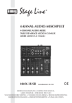
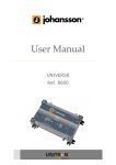
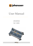
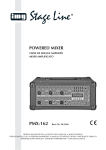
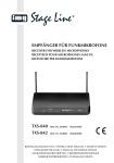
1
3-KANAL-AUDIO-MISCHPULT 3-CHANNEL AUDIO MIXER TABLE DE MIXAGE AUDIO 3 CANAUX MIXER AUDIO A 3 CANALI MMX-512 MMX-512USB Best.-Nr. 20.2440 Best.-Nr. 20.2450 BEDIENUNGSANLEITUNG • INSTRUCTION MANUAL MODE D’EMPLOI • ISTRUZIONI PER L’USO • MANUAL DE INSTRUCCIONES INSTRUKCJA OBSŁUGI • VEILIGHEIDSVOORSCHRIFTEN SIKKERHEDSOPLYSNINGER • SÄKERHETSFÖRESKRIFTER • TURVALLISUUDESTA D A CH F B CH Bevor Sie einschalten … GB Before switching on … Wir wünschen Ihnen viel Spaß mit Ihrem neuen Gerät von „img Stage Line“. Bitte lesen Sie diese Bedienungsanleitung vor dem Betrieb gründlich durch. Nur so lernen Sie alle Funktionsmöglichkeiten kennen, vermeiden Fehlbedienungen und schützen sich und Ihr Gerät vor eventuellen Schäden durch unsachgemäßen Gebrauch. Heben Sie die Anleitung für ein späteres Nachlesen auf. We wish you much pleasure with your new “img Stage Line” unit. Please read these operating instructions carefully prior to operating the unit. Thus, you will get to know all functions of the unit, operating errors will be prevented, and yourself and the unit will be protected against any damage caused by improper use. Please keep the operating instructions for later use. Der deutsche Text beginnt auf der Seite 4. The English text starts on page 8. Avant toute installation … I Nous vous souhaitons beaucoup de plaisir à utiliser cet appareil “img Stage Line”. Lisez ce mode dʼemploi entièrement avant toute utilisation. Uniquement ainsi, vous pourrez apprendre lʼensemble des possibilités de fonctionnement de lʼappareil, éviter toute manipulation erronée et vous protéger, ainsi que lʼappareil, de dommages éventuels engendrés par une utilisation inadaptée. Conservez la notice pour pouvoir vous y reporter ultérieurement. Prima di accendere … Vi auguriamo buon divertimento con il vostro nuovo apparecchio di “img Stage Line”. Leggete attentamente le istruzioni prima di mettere in funzione lʼapparecchio. Solo così potete conoscere tutte le funzionalità, evitare comandi sbagliati e proteggere voi stessi e lʼapparecchio da eventuali danni in seguito ad un uso improprio. Conservate le istruzioni per poterle consultare anche in futuro. Il testo italiano inizia a pagina 16. La version française se trouve page 12. E Antes de la utilización … PL Le deseamos una buena utilización para su nuevo aparato “img Stage Line”. Por favor, lea estas instrucciones de uso atentamente antes de hacer funcionar el aparato. De esta manera conocerá todas las funciones de la unidad, se prevendrán errores de operación, usted y el aparato estarán protegidos en contra de todo daño causado por un uso inadecuado. Por favor, guarde las instrucciones para una futura utilización. Przed uruchomieniem … Życzymy zadowolenia z nowego produktu “img Stage Line”. Dzięki tej instrukcji obsługi będą państwo w stanie poznać wszystkie funkcje tego urządzenia. Stosując się do instrukcji unikną państwo błędów i ewentualnego uszkodzenia urządzenia na skutek nieprawidłowego użytkowania. Prosimy zachować instrukcję. Tekst polski zaczyna się na stronie 24. La versión española comienza en la página 20. NL B Voor u inschakelt … DK Wij wensen u veel plezier met uw nieuwe apparaat van “img Stage Line”. Lees de veiligheidsvoorschriften grondig door, alvorens het apparaat in gebruik te nemen. Zo behoedt u zichzelf en het apparaat voor eventuele schade door ondeskundig gebruik. Bewaar de handleiding voor latere raadpleging. Før du tænder … Tillykke med dit nye “img Stage Line” produkt. Læs sikkerhedsanvisningerne nøje før ibrugtagning, for at beskytte Dem og enheden mod skader, der skyldes forkert brug. Gem manualen til senere brug. Sikkerhedsanvisningerne findes på side 28. De veiligheidsvoorschriften vindt u op pagina 28. S Innan du slår på enheten … Vi önskar dig mycket glädje med din nya “img Stage Line” produkt. Läs igenom säkerhetsföreskrifterna innan enheten tas i bruk för att undvika skador till följd av felaktig hantering. Behåll instruktionerna för framtida bruk. Säkerhetsföreskrifterna återfinns på sidan 29. FIN Ennen kytkemistä … Toivomme Sinulle paljon miellyttäviä hetkiä uuden “img Stage Line” laitteen kanssa. Ennen laitteen käyttöä pyydämme Sinua huolellisesti tutustumaan turvallisuusohjeisiin. Näin vältyt vahingoilta, joita virheellinen laitteen käyttö saattaa aiheuttaa. Ole hyvä ja säilytä käyttöohjeet myöhempää tarvetta varten. Turvallisuusohjeet löytyvät sivulta 29. ® w w w.imgstageline.com 2 25 26 27 1 2 MONO MONO 3 4 7 13 8 14 5 17 6 18 22 9 19 10 11 15 12 16 23 20 24 21 25 26 1 2 MONO MONO 3 4 7 13 8 14 5 17 6 18 22 9 19 10 11 15 12 16 20 21 23 24 3 D A Bitte klappen Sie die Seite 3 heraus. Sie sehen dann immer die beschriebenen Bedienelemente und Anschlüsse. PHONES (19), den Pegel des Eingangssignals der Buchsen TAPE IN (17) 24 Lautstärkeregler MAIN MIX für das Summensignal, das auf alle Ausgänge gegeben wird 25 Ein-/Ausschalter POWER 26 Buchse AC POWER IN zum Anschluss des beiliegenden Steckernetzgeräts 27 nur bei Modell MMX-512USB USB-Anschluss (Typ B) zur Verbindung mit einem Computer; kann gleichzeitig als Ausgang (digitale Ausgabe des Summensignals) und als Eingang (Einspeisen von Audiodaten zur Wiedergabe über Kanal 4/5) genutzt werden 2 Hinweise für den sicheren Gebrauch CH 1 Übersicht der Bedienelemente und Anschlüsse 1 MIC-Eingang (XLR, sym.) zum Anschluss eines Mikrofons an den Mono-Kanal 1 2 – 4 LINE-Eingänge (6,3-mm-Klinke, sym.) zum Anschluss von Geräten mit Line-Ausgangspegel (z. B. Musikinstrumente, CD-Spieler) an den Mono-Kanal 1, den Stereo-Kanal 2/3 und den Stereo-Kanal 4/5 Hinweis: Bei Anschluss eines Mono-Geräts an einen Stereo-Kanal nur die Buchse L (MONO) verwenden. 4 5 Stereo-Summenausgang MAIN OUT (6,3-mmKlinke, asym.) zum Anschluss eines Verstärkers 6 Ausgang PHONES (6,3-mm-Klinke) zum Anschluss eines Stereo-Kopfhörers (Mindestimpedanz 32 Ω) Die Geräte (Mischpult und Steckernetzgerät) entsprechen allen erforderlichen Richtlinien der EU und sind deshalb mit gekennzeichnet. 7 Regler GAIN zum Einstellen der Eingangsverstärkung für Kanal 1 8 Höhenregler HIGH für Kanal 1 WARNUNG Das Netzgerät wird mit lebensgefährlicher Netzspannung (230 V~) versorgt. Nehmen Sie deshalb nie selbst Eingriffe am Gerät vor. Es besteht die Gefahr eines elektrischen Schlages. 9 Bassregler LOW für Kanal 1 Beachten Sie auch unbedingt die folgenden Punkte: 10 Übersteuerungsanzeige PK für Kanal 1; leuchtet sie permanent, den Kanalpegel mithilfe des Reglers GAIN (7) und/oder der Klangregler (8 und 9) reduzieren G Die Geräte sind nur zur Verwendung im Innenbereich geeignet. Schützen Sie sie vor Tropf- und Spritzwasser, hoher Luftfeuchtigkeit und Hitze (zulässiger Einsatztemperaturbereich 0 – 40 °C). 11 Panoramaregler PAN für Kanal 1 zum Platzieren des Mono-Signals im Stereo-Klangbild G Stellen Sie keine mit Flüssigkeit gefüllten Gefäße z. B. Trinkgläser, auf die Geräte. 12 Lautstärkeregler LEVEL für Kanal 1 G 13 Balanceregler BAL für Kanal 2/3 14 Lautstärkeregler LEVEL für Kanal 2/3 Die im Mischpult entstehende Wärme muss durch Luftzirkulation abgegeben werden. Decken Sie darum die Lüftungsöffnungen nicht ab. 15 Balanceregler BAL für Kanal 4/5 G 16 Lautstärkeregler LEVEL für Kanal 4/5 17 Stereo-Eingang TAPE IN (Cinch) zum Anschluss eines zusätzlichen Geräts mit Line-Ausgangspegel, z. B. Recorder zur Wiedergabe 18 Stereo-Ausgang REC OUT (Cinch) zum Anschluss eines Recorders zur Aufnahme 19 Taste TAPE TO PHONES: bei gedrückter Taste wird das Signal der Buchsen TAPE IN (17) auf den Kopfhörerausgang PHONES (6) geschaltet und über die LED-Pegelanzeige (23) angezeigt. Nehmen Sie das Mischpult nicht in Betrieb bzw. ziehen Sie sofort das Netzgerät aus der Steckdose, 1. wenn sichtbare Schäden am Mischpult oder am Netzgerät vorhanden sind, 2. wenn nach einem Sturz oder Ähnlichem der Verdacht auf einen Defekt besteht, 3. wenn Funktionsstörungen auftreten. Geben Sie die Geräte in jedem Fall zur Reparatur in eine Fachwerkstatt. G Verwenden Sie für die Reinigung nur ein trockenes, weiches Tuch, niemals Wasser oder Chemikalien. G Werden die Geräte zweckentfremdet, nicht richtig angeschlossen, falsch bedient oder nicht fachgerecht repariert, kann keine Haftung für daraus resultierende Sach- oder Personenschäden und keine Garantie für die Geräte übernommen werden. 20 Taste TAPE TO MIX: bei gedrückter Taste wird das Signal der Buchsen TAPE IN (17) auf das Summensignal geschaltet 21 Lautstärkeregler für den Kopfhörer an der Buchse PHONES (6) 22 Betriebsanzeige POWER 23 LED-Pegelanzeige: zeigt den Pegel des Summensignals oder, bei gedrückter Taste TAPE TO Sollen die Geräte endgültig aus dem Betrieb genommen werden, übergeben Sie sie zur umweltgerechten Entsorgung einem örtlichen Recyclingbetrieb. 3 Einsatzmöglichkeiten Dieses Mischpult mit drei Eingangskanälen (1 × mono, 2 × stereo) ist für Tonabmischungen für Beschallungsoder Aufnahmezwecke geeignet. Es bietet Anschlussmöglichkeiten für bis zu vier Tonquellen mit Line-Ausgangspegel (z. B. Musikinstrument, CD-Spieler), ein Mikrofon, ein Tonaufnahmegerät und einen Kopfhörer. Das Modell MMX-512USB besitzt zusätzlich eine USB-Audio-Schnittstelle (USB 1.1 kompatibel) zum Anschluss an einen Computer. Der USB-Anschluss arbeitet im Vollduplex-Betrieb, d. h. er kann gleichzeitig als Ausgang (zur digitalen Ausgabe des Summensignals an den Computer) und als Eingang (zur Übertragung von Audiodaten vom Computer zum Mischpult) genutzt werden. Für den Betrieb des Mischpults mit dem Computer kann die mit dem Betriebssystem mitgelieferte Audio-Software verwendet werden oder eine zusätzlich installierte Audio-Software. Verschiedene Audio-Wiedergabe- und - Aufnahmeprogramme sind kostenlos im Internet erhältlich. 4 Inbetriebnahme Vor dem Anschließen von Geräten oder vor dem Ändern bestehender Anschlüsse den Summenregler MAIN MIX (24) für die Gesamtlautstärke immer ganz nach links zurückdrehen. 4.1 Anschluss der Tonquellen Es lassen sich ein Mikrofon und mehrere Tonquellen mit Line-Ausgangspegel (z. B. Musikinstrumente, CDSpieler) anschließen. 4.1.1 Eingangskanäle 1, 2 /3 und 4/5 Alle Eingänge der drei Kanäle sind symmetrisch ausgelegt. 1) An den Mono-Kanal 1 lässt sich entweder ein Mikrofon an die XLR-Buchse MIC (1) oder ein MonoLine-Gerät an die Klinkenbuchse LINE 1 (2) anschließen. Da nicht zwischen dem Mikrofon- und dem Line-Eingang umgeschaltet werden kann, nicht beide Eingänge gleichzeitig verwenden. 2) An die Stereo-Kanäle 2/3 und 4/5 kann jeweils ein Stereo-Line-Gerät an die Klinkenbuchsen LINE 2/3 (3) bzw. LINE 4/5 (4) angeschlossen werden: L (MONO) = linker Kanal, R = rechter Kanal. Bei Anschluss eines Mono-Geräts nur die Buchse L (MONO) verwenden. Das Eingangssignal wird dann intern auf den rechten und linken Kanal geschaltet. Hinweis: Bei dem Modell MMX-512USB belegen das Eingangssignal der Buchsen LINE 4/5 und das Eingangssignal der USB-Buchse den gleichen Kanal. Da nicht zwischen dem Line- und dem USB-Eingang umgeschaltet werden kann, nicht beide Eingänge gleichzeitig verwenden. Anderenfalls erhält der Kanal 4/5 das Mischsignal beider Eingänge. 4.1.2 Eingang TAPE IN Ein zusätzliches Gerät mit Line-Ausgangspegel, wie z. B. ein Recorder für die Wiedergabe, kann an die Cinch-Buchsen TAPE IN (17) angeschlossen werden: L = linker Kanal, R = rechter Kanal. 4.2 D A CH Anschluss von Verstärker, Recorder und Kopfhörer Ein Verstärker kann an die Klinkenbuchsen MAIN OUT (5) angeschlossen werden und ein Recorder zur Aufnahme an die Cinch-Buchsen REC OUT (18): L = linker Kanal, R = rechter Kanal. An die Klinkenbuchse PHONES (6) kann ein Stereo-Kopfhörer mit einer Mindestimpedanz von 32 Ω angeschlossen werden. An allen Ausgängen steht das mit dem Regler MAIN MIX (24) eingestellte Summensignal zur Verfügung. Hinweis: Ist das Mischpult sowohl mit einem Computer verbunden (nur bei Modell MMX-512USB möglich → Kap. 4.4) als auch mit Geräten, die über das Netzkabel geerdet sind (z. B. Verstärker), können aufgrund von Masseschleifen Brummstörungen auftreten. Um diese Störungen zu beseitigen, kann das Mischpult über ein Massetrennfilter (z. B. FGA-102 aus dem Programm von „img Stage Line“) mit dem jeweiligen Gerät verbunden werden. 4.3 Anschluss der Stromversorgung Das beiliegende Steckernetzgerät mit der Buchse AC POWER IN (26) verbinden. Damit sich die Verbindung nicht löst, die Mutter am Stecker festdrehen. Dann das Netzgerät in eine Steckdose (230 V~/50 Hz) stecken. 4.4 Betrieb mit einem Computer (nur bei MMX-512USB) Über die USB-Buchse (27) können digitale Audiosignale in beide Richtungen zwischen Mischpult und Computer übertragen werden, auch gleichzeitig. Verwendung als Eingang: Über die USB-Buchse eingespeiste Audiosignale werden auf den Kanal 4/5 gegeben. Verwendung als Ausgang: Die USB-Buchse gibt das mit dem Regler MAIN MIX (24) eingestellte Summensignal aus. Die USB-Buchse lässt sich nur in Verbindung mit einem Computer nutzen. Wiedergabegeräte oder Speichermedien mit USB-Anschluss können nicht direkt mit dem Mischpult verbunden werden. 1) Den Computer hochfahren und das Mischpult über den Schalter POWER (25) einschalten. 2) Vor dem Herstellen der USB-Verbindung den Regler LEVEL (16) für den Kanal 4/5 ganz nach links zurückdrehen. 3) Die USB-Buchse des Mischpults über ein USBKabel (z. B. über das als Zubehör erhältliche Kabel USB-203AB) mit einem USB-Anschluss am Computer verbinden: Die USB-Schnittstelle des Mischpults wird als externes USB-Gerät erkannt, je nach Betriebssystem des Computers z. B. als „USB Audio“, „USB Audiogerät“ oder „USB Audio CODEC“. Die 5 erforderlichen Treiber (Standardtreiber des Betriebssystems) werden automatisch installiert. D A Hinweis: In einigen Fällen kann es erforderlich sein, eine manuelle Pfadzuweisung der Treiber vorzunehmen, wenn diese nicht automatisch vom Betriebssystem gefunden werden. Die angeforderten Treiber ggf. über die Betriebssystem-Original-CD oder das Internet nachinstallieren, wenn sie nicht auf dem Computer vorhanden sind. CH 4) Die verwendete Abspiel-/Aufnahmesoftware aufrufen und dort die erforderlichen Einstellungen für die Tonwiedergabe über das Mischpult bzw. Tonaufnahme vom Mischpult vornehmen (→ Anleitung der Software). Das Mischpult kann dann anhand des Kapitels 5.2 bedient werden. Falls kein Ton zu hören ist, folgende Toneinstellungen des Computer-Betriebssystems überprüfen: – Toneingabe und -ausgabe müssen richtig zugewiesen sein: Wird die USB-Schnittstelle zur Übertragung von Audiodaten zum Mischpult verwendet, muss sie als Wiedergabegerät (Gerät für die Tonausgabe) angewählt sein. Wird die USB-Schnittstelle zur Ausgabe des Summensignals an den Computer verwendet, muss sie als Eingabegerät für die Tonaufnahme (Gerät für die Toneingabe) angewählt sein. – Der Ton muss eingeschaltet sein. 2) Um Kanal 1 auszusteuern, ein Tonsignal auf den Kanal geben und den Regler LEVEL (12) so weit aufdrehen, dass die LED-Pegelanzeige (23) bei 0 dB aufleuchtet. Der Regler sollte ungefähr zu 2⁄ 3 aufgedreht sein. Ist er zu weit oder zu wenig aufgedreht, die Eingangsverstärkung des Signals mit dem Regler GAIN (7) anpassen. Danach den Klang mit dem Höhenregler HIGH (8) und dem Bassregler LOW (9) einstellen. Die Übersteuerungsanzeige PK (10) sollte höchstens bei Musikspitzen kurz aufleuchten. Leuchtet sie permanent, den Regler GAIN und/oder die Klangregler entsprechend zurückdrehen. Die Signale der Kanäle 2/3 und 4/5 mit den Lautstärkereglern LEVEL (14 und 16) dazumischen. Die Regler LEVEL nicht benutzter Kanäle ganz nach links zurückdrehen. – Die entsprechenden Lautstärkeregler dürfen nicht auf Minimum eingestellt sein. 3) Für Kanal 1 mit dem Panoramaregler PAN (11) das Mono-Signal im Stereo-Klangbild platzieren und für die Kanäle 2/3 und 4/5 mit den Reglern BAL (13 und 15) die Balance der Stereo-Signale einstellen. 5 Bedienung 5.1 Ein- /Ausschalten 4) Soll das Eingangssignal der Buchsen TAPE IN (17) zusätzlich auf das Mischsignal gegeben werden, die Taste TAPE TO MIX (20) drücken. Soll ausschließlich das TAPE-IN-Signal auf die Ausgänge gegeben werden, die Taste TAPE TO MIX drücken und die Regler LEVEL (12, 14, 16) der Eingangskanäle ganz nach links zurückdrehen. Um Einschaltgeräusche zu vermeiden, vor dem Einschalten den Summenregler MAIN MIX (24) ganz nach links zurückdrehen. Mit dem Schalter POWER (25) wird das Mischpult ein- und ausgeschaltet. Bei eingeschaltetem Gerät leuchtet die Betriebsanzeige POWER (22). Wird das Mischpult nach dem Betrieb längere Zeit nicht benutzt, das Steckernetzgerät aus der Steckdose ziehen, da es selbst bei ausgeschaltetem Mischpult einen geringen Strom verbraucht. 5.2 Tonquellen mischen VORSICHT Stellen Sie die Lautstärke der Audioanlage und die Kopfhörerlautstärke nie sehr hoch ein. Hohe Lautstärken können auf Dauer das Gehör schädigen! Das Ohr gewöhnt sich an hohe Lautstärken und empfindet sie nach einiger Zeit als nicht mehr so hoch. Erhöhen Sie darum eine hohe Lautstärke nach der Gewöhnung nicht weiter. Die folgenden Bedienschritte dienen nur als Hilfestellung, es sind auch andere Vorgehensweisen möglich. 6 1) Als Grundeinstellung vorerst a) Den Regler GAIN (7), die Klangregler HIGH (8) und LOW (9) und die Regler PAN (11) und BAL (13 und 15) in die Mittelstellung drehen. b) die beiden TAPE-Tasten (19 und 20) ausrasten. c) alle Regler LEVEL (12, 14, 16) ganz nach links zurückdrehen. d) den Regler MAIN MIX (14) für die Gesamtlautstärke bis auf ca. 2⁄ 3 des Maximums aufdrehen. 5) Mit dem Regler MAIN MIX (24) anhand der LEDPegelanzeige (23) die Lautstärke des Summensignals (Summe aller Eingangssignale) einstellen, das auf alle Mischpult-Ausgänge gegeben wird. In der Regel wird eine optimale Aussteuerung erreicht, wenn die 0-dB-LEDs leuchten und die PEAK-LEDs höchstens bei Musikspitzen kurz aufleuchten. Ist der Ausgangspegel des Mischpults jedoch für das nachfolgende Gerät zu hoch, muss das Summensignal entsprechend niedriger eingestellt werden. 6) Die Kopfhörerlautstärke mit dem Regler (21) einstellen und mit der Taste TAPE TO PHONES (19) das Abhörsignal für den Kopfhörer wählen: – Ist die Taste nicht gedrückt, wird das mit dem Regler MAIN MIX (24) eingestellte Summensignal über den Kopfhörer abgehört und von der Pegelanzeige (23) angezeigt. – Ist die Taste gedrückt, wird das Eingangssignal der Buchsen TAPE IN (17) über den Kopfhörer abgehört und über die Pegelanzeige angezeigt. 6 Technische Daten Anschlüsse Eingang MIC, mono Empfindlichkeit: . . . . . . . . . . 0,7 mV Buchse: . . . . . . . . . . . . . . . . XLR, sym. Eingang LINE 1, mono Empfindlichkeit: . . . . . . . . . . 10 mV Buchse: . . . . . . . . . . . . . . . . 6,3-mm-Klinke, sym. Eingänge 2/3 und 4/5, stereo Empfindlichkeit: . . . . . . . . . . 85 mV Buchsen: . . . . . . . . . . . . . . . 6,3-mm-Klinke, sym. Eingang TAPE IN, stereo: Empfindlichkeit: . . . . . . . . . . 150 mV Buchsen: . . . . . . . . . . . . . . . Cinch, asym. D Allgemein Frequenzbereich: . . . . . . . . . . 20 – 20 000 Hz Klirrfaktor: . . . . . . . . . . . . . . . . < 0,02 % Störabstand: . . . . . . . . . . . . . . 80 dB, bewertet Übersprechen: . . . . . . . . . . . . -63 dB Klangregler LOW: . . . . . . . . . . ±15 dB/100 Hz Klangregler HIGH: . . . . . . . . . ±15 dB/10 kHz Stromversorgung: . . . . . . . . . . 2 × 18 V~/300 mA über beiliegendes Steckernetzgerät (230 V~/50 Hz/20 VA) Einsatztemperatur: . . . . . . . . . 0 – 40 °C Ausgang MAIN MIX, stereo Nennpegel/Impedanz: . . . . . 0,775 V/120 Ω Buchsen: . . . . . . . . . . . . . . . 6,3-mm-Klinke, asym. Abmessungen (B × H × T) MMX-512: . . . . . . . . . . . . . . 150 × 57 × 215 mm MMX-512USB: . . . . . . . . . . . 175 × 57 × 215 mm Ausgang REC OUT, stereo Nennpegel/Impedanz: . . . . . 520 mV/1 kΩ Buchsen . . . . . . . . . . . . . . . . Cinch, asym. Gewicht MMX-512: . . . . . . . . . . . . . . 950 g MMX-512USB: . . . . . . . . . . . 1,1 kg Ausgang PHONES, stereo Kopfhörerimpedanz . . . . . . . ≥ 32 Ω Buchse: . . . . . . . . . . . . . . . . 6,3-mm-Klinke USB, Vollduplex (bei MMX-512USB) Format: . . . . . . . . . . . . . . . . USB 1.1 kompatibel Buchse: . . . . . . . . . . . . . . . . Typ B A CH geeignetes Betriebssystem für USB-Betrieb (bei MMX-512USB) Windows 98 SE, Windows ME, Windows 2000, Windows XP, Windows XP Professional, Mac OS 9.1, Mac OS X Windows ist ein registriertes Warenzeichen der Microsoft Corporation in den USA und anderen Ländern. Mac OS ist ein registriertes Warenzeichen von Apple Computer, Inc. in den USA und anderen Ländern. Änderungen vorbehalten. Diese Bedienungsanleitung ist urheberrechtlich für MONACOR ® INTERNATIONAL GmbH & Co. KG geschützt. Eine Reproduktion für eigene kommerzielle Zwecke – auch auszugsweise – ist untersagt. 7 GB Please unfold page 3. Then you will always see the operating elements and connections described. 1 Operating Elements and Connections 1 MIC input (XLR, bal.) for connecting a microphone to mono channel 1 24 Volume control MAIN MIX for the master signal sent to all outputs 25 POWER switch 26 Jack AC POWER IN for connecting the plug-in power supply unit provided 27 for model MMX-512USB only USB port (type B) for connection to a computer; to be used simultaneously as an output (digital output of the master signal) and as an input (feedin of audio data for reproduction via channel 4/5) 2 Safety Notes 2 – 4 LINE inputs (6.3 mm jacks, bal.) for connecting units with line output level (e. g. musical instruments, CD players) to mono channel 1, stereo channel 2/3 and stereo channel 4/5 Note: When connecting a mono unit to a stereo channel, only use the jack L (MONO). 8 5 Stereo master output MAIN OUT (6.3 mm jacks, unbal.) for connecting an amplifier 6 Output PHONES (6.3 mm jack) for connecting stereo headphones (minimum impedance 32 Ω) 7 Control GAIN for adjusting the input amplification for channel 1 8 Treble control HIGH for channel 1 9 Bass control LOW for channel 1 10 Overload LED PK for channel 1; if it is permanently illuminated, reduce the channel level by means of the control GAIN (7) and/or the tone controls (8 and 9) 11 Panorama control PAN for channel 1 for placing the mono signal in the stereo sound 12 Volume control LEVEL for channel 1 13 Balance control BAL for channel 2/3 14 Volume control LEVEL for channel 2/3 15 Balance control BAL for channel 4/5 16 Volume control LEVEL for channel 4/5 17 Stereo input TAPE IN (phono jacks) for connecting an additional unit with line output level, e. g. recorder for reproduction 18 Stereo output REC OUT (phono jacks) for connecting a recorder 19 Button TAPE TO PHONES: when the button is pressed, the signal of the jacks TAPE IN (17) will be switched to the headphone output PHONES (6) and indicated via the LED VU-meter (23) 20 Button TAPE TO MIX: when the button is pressed, the signal of the jacks TAPE IN (17) will be switched to the master signal 21 Volume control for the headphones connected to the jack PHONES (6) 22 POWER LED 23 LED VU-meter: will indicate the level of the master signal or, when the button TAPE TO PHONES (19) is pressed, the level of the input signal of the jacks TAPE IN (17) The units (mixer and plug-in power supply unit) correspond to all required directives of the EU and are therefore marked with . WARNING The power supply unit uses dangerous mains voltage (230 V~). Leave servicing to skilled personnel only; inexpert handling may result in electric shock. Please observe the following items in any case: G The units are suitable for indoor use only. Protect them against dripping water and splash water, high air humidity, and heat (admissible ambient temperature range 0 – 40 °C). G Do not place any vessel filled with liquid on the units, e. g. a drinking glass. G The heat generated within the mixer must be dissipated by air circulation; therefore, never cover the air vents. G Do not operate the mixer and immediately disconnect the power supply unit from the socket 1. if the mixer or the power supply unit is visibly damaged, 2. if a defect might have occurred after a unit was dropped or suffered a similar accident, 3. if malfunctions occur. In any case the units must be repaired by skilled personnel. G For cleaning only use a dry, soft cloth; never use water or chemicals. G No guarantee claims for the units and no liability for any resulting personal damage or material damage will be accepted if the units are used for other purposes than originally intended, if they are not correctly connected or operated, or if they are not repaired in an expert way. If the units are to be put out of operation definitively, take them to a local recycling plant for a disposal which is not harmful to the environment. 3 Applications This mixer with three input channels (1 × mono, 2 × stereo) is ideally suited for sound mixing used for PA applications or recording applications. It allows to connect a maximum of four audio sources with line output level (e. g. musical instruments, CD players), a microphone, an audio recorder and headphones. Model MMX-512USB is additionally equipped with a USB audio interface (USB 1.1 compatible) for connecting a computer. The USB port operates in full duplex mode, i. e. it can be simultaneously used as an output (for digital output of the master signal to the computer) and as an input (for transmitting audio data from the computer to the mixer). For operating the mixer with the computer, either use the audio software supplied with the operating system or an audio software installed additionally. Various programmes for audio reproduction/recording are available on the Internet, free of charge. 4 4.2 Connecting an amplifier, a recorder and headphones GB An amplifier can be connected to the 6.3 mm jacks MAIN OUT (5) and a recorder to the phono jacks REC OUT (18): L = left channel, R = right channel. The 6.3 mm jack PHONES (6) allows to connect stereo headphones with a minimum impedance of 32 Ω. At all outputs, the master signal adjusted with the control MAIN MIX (24) is available. Note: If the mixer is connected both to a computer (model MMX-512USB only → chapter 4.4) and to units grounded via the mains cable (e. g. amplifiers), hum noise may occur due to ground loops. To eliminate this noise, connect the mixer to the corresponding unit via a ground isolator (e. g. FGA-102 from the product range of “img Stage Line”). 4.3 Connecting the power supply Connect the plug-in power supply unit provided to the jack AC POWER IN (26). To secure the connection, fasten the nut on the plug. Then connect the power supply unit to a mains socket (230 V~/50 Hz). Setting the Mixer into Operation Prior to connecting any units or to changing any existing connections, always set the master control MAIN MIX (24) for the overall volume to the left stop. 4.1 Connecting the audio sources The mixer allows to connect a microphone and several audio sources with line output level (e. g. musical instruments, CD players). 4.1.1 Input channels 1, 2 /3 and 4/5 All inputs of the three channels are balanced. 1) For mono channel 1, either connect a microphone to the XLR jack MIC (1) or a mono line unit to the 6.3 mm jack LINE 1 (2). As it will not be possible to switch between the microphone input and the line input, never use both inputs at the same time. 2) For the stereo channels 2/3 and 4/5, respectively connect a stereo line unit to the 6.3 mm jacks LINE 2/3 (3) or LINE 4/5 (4): L (MONO) = left channel, R = right channel. When connecting a mono unit, only use the jack L (MONO). The input signal will then be switched internally to the right and left channels. Note: For model MMX-512USB, the input signal of the jacks LINE 4/5 and the input signal of the USB jack use the same channel. As it will not be possible to switch between the line input and the USB input, never use both inputs at the same time; otherwise channel 4/5 will receive the mixed signal of both inputs. 4.1.2 Input TAPE IN An additional unit with line output level (e. g. a recorder for reproduction) can be connected to the phono jacks TAPE IN (17): L = left channel, R = right channel. 4.4 Operation with a computer (for MMX-512USB only) Via the USB port (27), digital audio signals can be transmitted in both directions between the mixer and the computer, even at the same time. When used as an input: Audio signals fed in via the USB port will be sent to channel 4/5. When used as an output: The USB port will provide the master signal adjusted with the control MAIN MIX (24). The USB port can only be used in connection with a computer. Direct connection of reproducers or storage media with USB port to the mixer will not be possible. 1) Start the computer and switch on the mixer via the POWER switch (25). 2) Prior to making the USB connection, set the control LEVEL (16) for channel 4/5 to the left stop. 3) Connect the USB port of the mixer via a USB cable (e. g. via the cable USB-203AB available as an accessory) to a USB port on the computer: The USB interface of the mixer will be recognized as an external USB unit, e. g. as “USB Audio”, “USB Audio Device” or “USB Audio CODEC”, depending on the operating system of the computer. The drivers required (standard drivers of the operating system) will be installed automatically. Note: In some cases, it may be necessary to make a manual path assignment of the drivers if they are not found automatically by the operating system. If necessary, install the required drivers via the original CD of the operating system or via the Internet if they are not available on the computer. 9 GB 4) Call the reproduction/recording software used and make the required adjustments for audio reproduction via the mixer or for audio recording from the mixer (→ software instructions). It will then be possible to operate the mixer according to chapter 5.2. If there is no sound, check the following sound adjustments of the operating system of the computer: – Audio input and output must be correctly assigned: If the USB interface is used for transmitting audio data to the mixer, it must be selected as a sound playback device (device for audio output). If the USB interface is used for sending the master signal to the computer, it must be selected as an input device for sound recording (device for audio input). – The sound must be switched on. Set the controls LEVEL of any channels that are not used to the left stop. – The corresponding volume controls must not be set to minimum. 3) Use the panorama control PAN (11) to place the mono signal in the stereo sound for channel 1 and the controls BAL (13 and 15) to adjust the balance of the stereo signals for channels 2/3 and 4/5. 5 Operation 5.1 Switching on /off 4) To feed the input signal of the jacks TAPE IN (17) also to the mixed signal, press the button TAPE TO MIX (20). To feed merely the TAPE IN signal to the outputs, press the button TAPE TO MIX and set the controls LEVEL (12, 14, 16) of the input channels to the left stop. To prevent switching noise, set the master control MAIN MIX (24) to the left stop before switching on. The mixer is switched on and off with the POWER switch (25). When the unit is switched on, the POWER LED (22) will light up. If the mixer is not used for a longer period after operation, disconnect the plug-in power supply unit from the mains socket as it will have a low power consumption even with the mixer switched off. 5.2 Mixing the audio sources CAUTION Never adjust the audio system and the headphones to a very high volume. Permanent high volumes may damage your hearing! The human ear will get accustomed to high volumes which do not seem to be that high after some time. Therefore, do not further increase a high volume after getting used to it. The following operating steps merely serve as an aid; other procedures are also possible. 1) First make the following basic adjustments: a) Set the control GAIN (7), the tone controls HIGH (8) and LOW (9), and the controls PAN (11) and BAL (13 and 15) to mid-position. b) Disengage the two TAPE buttons (19 and 20). c) Set all LEVEL controls (12, 14, 16) to the left stop. d) Set the control MAIN MIX (14) for the overall volume to approx. 2⁄ 3 of its maximum. 10 2) For optimum level control of channel 1, feed an audio signal to the channel and advance the control LEVEL (12) so far that the LED VU-meter (23) will light up at 0 dB. The control should be advanced to approx. 2⁄ 3 of its maximum. If it is advanced too far or not far enough, adapt the input amplification of the signal with the control GAIN (7). Then adjust the sound with the treble control HIGH (8) and the bass control LOW (9). The overload LED PK (10) should shortly light up with music peaks, if at all. If it is permanently illuminated, turn back the control GAIN and/or the tone controls accordingly. Add the signals of the channels 2/3 and 4/5 with the volume controls LEVEL (14 and 16). 5) By means of the LED VU-meter (23), adjust the volume of the master signal (total of all input signals) that is sent to all mixer outputs with the control MAIN MIX (24). Usually there will be an optimum level control when the 0 dB LEDs are illuminated and the PEAK LEDs light up shortly with music peaks, if at all. However, if the output level of the mixer is too high for the following unit, control the master signal to a lower level accordingly. 6) Adjust the headphone volume with the control (21) and select the monitoring signal for the headphones with the button TAPE TO PHONES (19): – When the button is not pressed, the master signal adjusted via the control MAIN MIX (24) will be monitored via the headphones and indicated via the VU-meter (23). – When the button is pressed, the input signal of the jacks TAPE IN (17) will be monitored via the headphones and indicated via the VU-meter. 6 Specifications Connections Input MIC, mono Sensitivity: . . . . . . . . . . . . . . 0.7 mV Jack: . . . . . . . . . . . . . . . . . . XLR, bal. Input LINE 1, mono Sensitivity: . . . . . . . . . . . . . . 10 mV Jack: . . . . . . . . . . . . . . . . . . 6.3 mm jack, bal. Inputs 2/3 and 4/5, stereo Sensitivity: . . . . . . . . . . . . . . 85 mV Jacks: . . . . . . . . . . . . . . . . . . 6.3 mm jacks, bal. Input TAPE IN, stereo Sensitivity: . . . . . . . . . . . . . . 150 mV Jacks: . . . . . . . . . . . . . . . . . . phono jacks, unbal. GB General information Frequency range: . . . . . . . . . . 20 – 20 000 Hz THD: . . . . . . . . . . . . . . . . . . . . < 0.02 % S/N ratio: . . . . . . . . . . . . . . . . 80 dB, weighted Crosstalk: . . . . . . . . . . . . . . . . -63 dB Tone control LOW: . . . . . . . . . ±15 dB/100 Hz Tone control HIGH: . . . . . . . . . ±15 dB/10 kHz Power supply: . . . . . . . . . . . . . 2 × 18 V~/300 mA via plug-in power supply unit provided (230 V~/50 Hz/20 VA) Ambient temperature: . . . . . . . 0 – 40 °C Output MAIN MIX, stereo Nominal level/impedance: . . 0.775 V /120 Ω Jacks: . . . . . . . . . . . . . . . . . . 6.3 mm jacks, unbal. Dimensions (W × H × D) MMX-512: . . . . . . . . . . . . . . 150 × 57 × 215 mm MMX-512USB: . . . . . . . . . . . 175 × 57 × 215 mm Output REC OUT, stereo Nominal level/impedance: . . 520 mV/1 kΩ Jacks: . . . . . . . . . . . . . . . . . . phono jacks, unbal. Weight MMX-512: . . . . . . . . . . . . . . 950 g MMX-512USB: . . . . . . . . . . . 1.1 kg Output PHONES, stereo Headphone impedance: . . . . ≥ 32 Ω Jack: . . . . . . . . . . . . . . . . . . 6.3 mm jack USB, full duplex (for MMX-512USB) Format: . . . . . . . . . . . . . . . . USB 1.1. compatible Jack: . . . . . . . . . . . . . . . . . . type B suitable operating system for USB mode (for MMX-512USB) Windows 98 SE, Windows ME, Windows 2000, Windows XP, Windows XP Professional, Mac OS 9.1, Mac OS X Windows is a registered trademark of Microsoft Corporation in the USA and other countries. Mac OS is a registered trademark of Apple Computer, Inc. in the USA and other countries. Subject to technical modification. All rights reserved by MONACOR ® INTERNATIONAL GmbH & Co. KG. No part of this instruction manual may be reproduced in any form or by any means for any commercial use. 11 F B Ouvrez le présent livret page 3 de manière à visualiser les éléments et branchements. CH 1 Eléments et branchements 1 Entrée MIC (XLR, sym.) pour brancher un microphone au canal mono 1 2 – 4 Entrées LINE (jack 6,35, sym.) pour brancher des appareils à niveau de sortie ligne (par exemple instruments de musique, lecteurs CD) au canal mono 1, au canal stéréo 2/3 et au canal stéréo 4/5 Remarque : si vous branchez un appareil mono à un canal stéréo, utilisez uniquement la prise L (MONO). 12 5 Sortie master stéréo MAIN OUT (jack 6,35, asym.) pour brancher un amplificateur 6 Sortie PHONES (jack 6,35) pour brancher un casque stéréo (impédance minimale 32 Ω). 7 Potentiomètre de réglage GAIN pour régler lʼamplification dʼentrée pour le canal 1 8 Potentiomètre de réglage des aigus HIGH pour le canal 1 9 Potentiomètre de réglage des graves LOW pour le canal 1 10 LED témoin de surcharge PK pour le canal 1 ; si elle brille en continu, diminuez le niveau du canal avec le réglage GAIN (7) et/ou les réglages (8 et 9) de lʼégaliseur 11 Réglage de panoramique PAN pour le canal 1 pour placer le signal mono dans le son stéréo 12 Potentiomètre de réglage de volume LEVEL pour le canal 1 13 Potentiomètre de réglage de balance BAL pour le canal 2/3 14 21 Réglage de volume prise PHONES (6) pour le casque relié à la 22 Témoin de fonctionnement POWER 23 VU-mètre à LEDs : indique le niveau du signal master ou, si la touche TAPE TO PHONES (19) est enfoncée, le niveau du signal dʼentrée des prises TAPE IN (17) 24 Potentiomètre de réglage de volume MAIN MIX pour le signal master envoyé à toutes les sorties 25 Interrupteur Marche/Arrêt POWER 26 Prise AC POWER IN pour brancher le bloc secteur livré 27 Uniquement sur le modèle MMX-512USB : port USB (type B) pour relier à un ordinateur ; peut simultanément servir de sortie (sortie numérique du signal master) et dʼentrée (insertion de données audio pour la reproduction via canal 4/5). 2 Conseils de sécurité et dʼutilisation Les appareils (table de mixage et le bloc secteur) répondent à toutes les directives nécessaires de lʼUnion européenne et portent donc le symbole . AVERTISSEMENT Le bloc secteur est alimenté par une tension dangereuse en 230 V~. Ne touchez jamais lʼintérieur de lʼappareil car, en cas de mauvaise manipulation, vous pouvez subir une décharge électrique. Respectez scrupuleusement les points suivants : G Potentiomètre de réglage de volume LEVEL pour le canal 2/3 Les appareils ne sont conçus que pour une utilisation en intérieur. Protégez-les des éclaboussures, de tout type de projections dʼeau, dʼune humidité élevée de lʼair et de la chaleur (température ambiante admissible 0 – 40 °C). G 15 Potentiomètre de réglage de balance BAL pour le canal 4/5 En aucun cas, vous ne devez pas poser dʼobjet contenant du liquide ou un verre sur lʼappareil. G 16 Potentiomètre de réglage de volume LEVEL pour le canal 4/5 17 Entrée stéréo TAPE IN (RCA) pour brancher un appareil supplémentaire avec niveau de sortie ligne, par exemple enregistreur pour la lecture La chaleur dégagée par la table de mixage doit être évacuée par une circulation correcte de lʼair. En aucun cas les ouïes de ventilation ne doivent être obturées. G Ne faites pas fonctionner la table de mixage et débranchez le bloc secteur immédiatement dans les cas suivants : 1. la table de mixage ou le bloc secteur présentent des dommages visibles. 2. après une chute ou accident similaire, vous avez un doute sur lʼétat de lʼappareil. 3. des dysfonctionnements apparaissent. Dans tous les cas, les dommages doivent être réparés par un technicien spécialisé. G Pour le nettoyage, utilisez un chiffon sec et doux, en aucun cas de produits chimiques ou dʼeau. 18 Sortie stéréo REC OUT (RCA) pour brancher un enregistreur 19 Touche TAPE TO PHONES : lorsque la touche est enfoncée, le signal des prises TAPE IN (17) est branché sur la sortie casque PHONES (6) et indiqué via le VU-mètre à LEDs (23). 20 Touche TAPE TO MIX : si la touche est enfoncée, le signal des prises TAPE IN (17) est commuté sur le signal master. G Nous déclinons toute responsabilité en cas de dommages corporels ou matériels résultants si les appareils sont utilisés dans un but autre que celui pour lequel ils ont été conçus, sʼils ne sont pas correctement branchés, utilisés ou sʼils ne sont pas réparés par une personne habilitée ; en outre, la garantie deviendrait caduque. Lorsque les appareils sont définitivement retirés du service, vous devez les déposer dans une usine de recyclage adaptée pour contribuer à leur élimination non polluante. 3 Possibilités dʼutilisation Cette table de mixage avec trois canaux dʼentrée (1 × mono, 2 × stéréo) est adaptée pour les mixages de son pour des applications de sonorisation ou dʼenregistrement. On peut brancher jusquʼà 4 sources audio avec niveau de sortie ligne (par exemple instrument de musique, lecteur CD), un microphone, un enregistreur et un casque. Le modèle MMX-512USB dispose en plus dʼune interface audio USB (compatible USB 1.1) pour brancher à un ordinateur. La connexion USB fonctionne en mode duplex intégral, elle peut être utilisée simultanément comme sortie (pour une sortie digitale du signal master vers lʼordinateur) et comme entrée (pour une transmission de données audio de lʼordinateur vers la table de mixage). Pour le fonctionnement de la table de mixage avec lʼordinateur, le logiciel audio livré avec le système dʼexploitation ou un autre logiciel audio installé en plus peut être utilisé. Différents programmes audio de lecture et dʼenregistrement sont disponibles gratuitement sur Internet. 4 Fonctionnement 2) On peut relier aux canaux stéréo 2/3 et 4/5 respectivement un appareil ligne stéréo aux prises jack LINE 2/3 (3) ou LINE 4/5 (4) : L (MONO) = canal gauche, R = canal droit. Si vous branchez un appareil mono, utilisez uniquement la prise L (MONO). Le signal dʼentrée est branché en interne sur le canal gauche et le canal droit. 4.1.2 Entrée TAPE IN Un appareil supplémentaire avec niveau de sortie ligne, par exemple un enregistreur pour la reproduction peut être relié aux prises RCA TAPE IN (17) : L = canal gauche, R = canal droit. 4.2 Branchement dʼun amplificateur, dʼun enregistreur et dʼun casque Reliez un amplificateur aux prises jack MAIN OUT (5) et un enregistreur aux prises RCA REC OUT (18) : L = canal gauche, R = canal droit. On peut relier un casque stéréo avec une impédance minimale de 32 Ω à la prise jack PHONES (6). Le signal master réglé avec le réglage MAIN MIX (24) est disponible à toutes les sorties. Conseil : Si la table de mixage est reliée aussi bien à un ordinateur (uniquement modèle MMX-512USB, voir chapitre 4.4) quʼà des appareils mis à la masse via le cordon secteur (par exemple amplificateur), des ronflements, générés par des bouclages de masse peuvent apparaître. Pour éliminer ces interférences la table de mixage peut être reliée, via un filtre dʼisolation (par exemple FGA-102 de la gamme “img Stage Line“), à lʼappareil correspondant. 4.3 Branchement de lʼalimentation Reliez le bloc secteur livré à la prise AC POWER IN (26) ; pour que la connexion ne se desserre pas, serrez fermement lʼécrou sur la fiche. Reliez ensuite le bloc secteur à une prise secteur 230 V~/50 Hz. 4.1 4.4 Branchement des sources audio 4.1.1 Canaux dʼentrées 1, 2 /3 et 4/5 Toutes les entrées des trois canaux sont configurées en symétrique. 1) On peut relier au canal mono 1 soit un microphone à la prise XLR MIC (1) soit un appareil mono ligne à la prise jack LINE 1 (2). Puisquʼon ne peut pas commuter entre lʼentrée micro et lʼentrée ligne, nʼutilisez pas simultanément les deux entrées. B CH Remarque : sur le modèle MMX-512USB, le signal dʼentrée des prises LINE 4/5 et le signal dʼentrée de la prise USB utilisent le même canal. Puisquʼon ne peut pas commuter entre lʼentrée ligne et lʼentrée USB, nʼutilisez pas simultanément les deux entrées. Sinon le canal 4/5 reçoit le signal de mixage des deux entrées. Avant dʼeffectuer les branchements des appareils ou de modifier les branchements existants, tournez le réglage master MAIN MIX (24) pour le volume général toujours entièrement à gauche. On peut relier un microphone et plusieurs sources audio avec niveau de sortie ligne (par exemple instruments de musique, lecteurs CD). F Fonctionnement avec un ordinateur (uniquement sur le modèle MMX-512USB) Via la prise USB (27), des signaux audio digitaux peuvent être transmis dans les deux sens entre la table de mixage et lʼordinateur, même simultanément. Utilisation comme entrée : Des signaux audio insérés via la prise USB sont dirigés vers le canal 4 / 5. Utilisation comme sortie : La prise USB sort le signal master réglé avec le réglage MAIN MIX (24). La prise USB ne peut être utilisée quʼen liaison avec un ordinateur. Les appareils de restitution ou les 13 F B CH médias de stockage avec port USB ne peuvent pas être directement reliés à la table de mixage. 1) Allumez lʼordinateur et la table de mixage avec lʼinterrupteur POWER (25). 2) Tournez le réglage LEVEL (16) pour le canal 4 / 5 entièrement à gauche avant dʼeffectuer la connexion USB. 3) Reliez la prise USB de la table de mixage via un cordon de liaison USB (par exemple via le cordon USB-203AB disponible en option), à un port USB sur lʼordinateur. Lʻinterface USB de la table de mixage est reconnue comme appareil USB externe, selon le système dʼexploitation de lʼordinateur par exemple comme “USB Audio”, “Appareil audio USB” ou “CODEC USB Audio”. Les drivers nécessaires (drivers standards du système dʼexploitation) sont installés automatiquement. Remarque : dans certains cas, il peut être nécessaire dʼattribuer manuellement les chemins dʼaccès des drivers sʼils ne sont pas automatiquement trouvés par le système dʼexploitation. Les drivers nécessaires peuvent si besoin être installés via le CD dʼorigine du système dʼexploitation ou via Internet sʼils ne sont pas sur lʼordinateur. 4) Appelez le logiciel de lecture/dʼenregistrement utilisé et effectuez les réglages nécessaires pour la restitution du son via la table de mixage ou pour lʼenregistrement du son depuis la table de mixage (voir notice du logiciel). La table de mixage peut ensuite être utilisée selon les indications du chapitre 5.2. Si aucun son nʼest audible, vérifiez les réglages suivants du système dʼexploitation de lʼordinateur : – Lʼentrée et la sortie du son doivent être correctement attribuées: Si lʼinterface USB est utilisée pour transmettre des données audio vers la table de mixage, elle doit être sélectionnée comme appareil de lecture (appareil pour sortie audio). Si lʼinterface USB est utilisée pour diriger le signal master vers lʼordinateur, elle doit être sélectionnée comme appareil dʼentrée (appareil pour lʼentrée du son). – Le son doit être allumé. – Les réglages de volume correspondants ne doivent pas être réglés sur le minimum. 5 5.1 Fonctionnement Marche /Arrêt Pour éviter tout bruit fort lors de lʼallumage, tournez le réglage master MAIN MIX (24) entièrement à gauche avant dʼallumer la table. La table de mixage peut être allumée ou éteinte avec lʼinterrupteur POWER (25). Lorsquʼelle est allumée, le témoin de fonctionnement POWER (22) brille. En cas de non utilisation prolongée, débranchez le bloc secteur de la prise secteur car même si la table de mixage est éteinte, le bloc secteur a une faible consommation. 14 5.2 Mixage des sources audio ATTENTION Ne réglez jamais le volume du système audio et du casque trop fort. Un volume trop élevé peut, à long terme, générer des troubles de lʼaudition. Lʼoreille humaine sʼhabitue à des volumes élevés et ne les perçoit plus comme tels au bout dʼun certain temps. Nous vous conseillons donc de régler le volume et de ne plus le modifier. Les étapes décrites ci-après ne sont que des propositions dʼutilisation, il est possible de procéder différemment. 1) Tout dʼabord, les réglages de base : a) Tournez le réglage GAIN (7), les réglages HIGH (8) et LOW (9) de lʼégaliseur, les réglages PAN (11) et BAL (13 et 15) sur la position médiane. b) Désenclenchez les deux touches TAPE (19 et 20). c) Tournez tous les réglages LEVEL (12, 14, 16) entièrement vers la gauche. d) Tournez le réglage MAIN MIX (14) pour le volume général à 2⁄ 3 environ du maximum. 2) Pour gérer le canal 1 de manière optimale, appliquez un signal audio sur le canal et tournez le réglage LEVEL (12) jusquʼà ce que le VU-mètre à LEDs (23) brille pour 0 dB. Le réglage devrait être tourné au 2⁄ 3 environ. Sʻil est trop ou pas assez poussé, adaptez lʼamplification dʼentrée du signal avec le réglage GAIN (7). Ensuite réglez la tonalité avec le réglage des aigus HIGH (8) et celui des graves LOW (9). La LED témoin de surcharge PK (10) ne devrait briller que brièvement pour des crêtes de musique. Si elle brille en permanence, tournez en arrière le réglage GAIN et/ou les réglages de lʼégaliseur en conséquence pour diminuer. Ajoutez les signaux des canaux 2/3 et 4 / 5 avec les réglages LEVEL (14 et 16). Tournez entièrement vers la gauche les réglages LEVEL des canaux inutilisés. 3) Placez le signal mono pour le canal 1, avec le réglage de panoramique PAN (11) dans le son stéréo et réglez la balance des signaux stéréo pour les canaux 2/3 et 4 / 5 avec les réglages BAL (13 et 15). 4) Pour appliquer le signal dʼentrée des prises TAPE IN (17) également au signal mixé, appuyez sur la touche TAPE TO MIX (20). Si seul le signal TAPE IN (17) doit être appliqué aux sorties, appuyez sur la touche TAPE TO MIX et tournez les réglages LEVEL (12, 14, 16) des canaux dʼentrée entièrement vers la gauche. 5) Avec le réglage MAIN MIX (24), réglez le volume du signal master (somme de tous les signaux dʼentrée) en fonction des indications du VU-mètre à LEDs (23) : ce signal est appliqué sur toutes les sorties de la table de mixage. En règle générale, le réglage est optimal lorsque les LEDs 0 dB brillent et les LEDs PEAK ne brillent que brièvement pour des passages élevés. Si le niveau de sortie de la table de mixage est trop élevé pour lʼappareil suivant, diminuez, en conséquence, le signal master. 6) Réglez le volume du casque avec le réglage (21) et avec la touche TAPE TO PHONES (19), sélectionnez le signal dʼécoute pour le casque : – si la touche nʼest pas enfoncée, le signal master réglé avec le réglage MAIN MIX (24) est écouté via le casque et indiqué par le VU-mètre (23). – si la touche est enfoncée, le signal dʼentrée des prises TAPE IN (17) est écouté via le casque et indiqué par le VU-mètre (23). 6 Caractéristiques techniques Branchements Entrée MIC, mono Sensibilité : . . . . . . . . . . . . . 0,7 mV Prise : . . . . . . . . . . . . . . . . . . XLR, sym. Entrée LINE 1, mono Sensibilité : . . . . . . . . . . . . . 10 mV Prise : . . . . . . . . . . . . . . . . . . jack 6,35, sym. Entrées 2/3 et 4 / 5, stéréo Sensibilité : . . . . . . . . . . . . . 85 mV Prises : . . . . . . . . . . . . . . . . . jack 6,35, sym. Généralités Bande passante : . . . . . . . . . . 20 – 20 000 Hz Taux de distorsion : . . . . . . . . < 0,02 % Rapport signal/bruit : . . . . . . . 80 dB, pondéré F B CH Diaphonie : . . . . . . . . . . . . . . . -63 dB Réglage des graves LOW : . . ±15 dB/100 Hz Réglage des aigus HIGH : . . . ±15 dB/10 kHz Alimentation : . . . . . . . . . . . . . 2 × 18 V~/300 mA par bloc secteur livré (230 V~/50 Hz/20 VA) Température fonc. : . . . . . . . . 0 – 40 °C Dimensions (L × H × P) MMX-512 : . . . . . . . . . . . . . . 150 × 57 × 215 mm MMX-512USB : . . . . . . . . . . 175 × 57 × 215 mm Poids MMX-512 : . . . . . . . . . . . . . . 950 g MMX-512USB : . . . . . . . . . . 1,1 kg système dʼexploitation adapté à un fonctionnement USB (pour MMX-512USB) Windows 98 SE, Windows ME, Windows 2000, Windows XP, Windows XP Professional, Mac OS 9.1, Mac OS X Entrée TAPE IN, stéréo Sensibilité : . . . . . . . . . . . . . 150 mV Prises : . . . . . . . . . . . . . . . . . RCA, asym. Sortie MAIN MIX, stéréo Niveau nominal/Impédance : 0,775 V/120 Ω Prises : . . . . . . . . . . . . . . . . . jack 6,35, asym. Sortie REC OUT, stéréo Niveau nominal/Impédance : 520 mV/1 kΩ Prises : . . . . . . . . . . . . . . . . . RCA, asym. Sortie PHONES, stéréo Impédance casque : . . . . . . ≥ 32 Ω Prise : . . . . . . . . . . . . . . . . . . jack 6,35 USB, duplex intégral (pour MMX-512USB) Format : . . . . . . . . . . . . . . . . compatible USB 1.1 Prise : . . . . . . . . . . . . . . . . . . type B Windows est une marque déposée de la société Microsoft Corporation aux EtatsUnis et dans d’autres pays. Mac OS est une marque déposée de la société Apple Computer, Inc. aux Etats-Unis et dans d’autres pays. Tout droit de modification réservé. Notice dʼutilisation protégée par le copyright de MONACOR ® INTERNATIONAL GmbH & Co. KG. Toute reproduction même partielle à des fins commerciales est interdite. 15 I Vi preghiamo di aprire completamente la pagina 3. Così vedrete sempre gli elementi di comando e i collegamenti descritti. 1 Elementi di comando e collegamenti 1 Ingresso MIC (XLR, simm.) per il collegamento di un microfono con il canale mono 1 24 Regolatore del volume MAIN MIX per il segnale delle somme portato su tutte le uscite 25 Interruttore on/off POWER 26 Presa AC POWER IN per il collegamento dellʼalimentatore a spina in dotazione 27 solo con il modello MMX-512USB Porta USB (tipo B) per il collegamento con un computer; può essere usata anche come uscita (output digitale del segnale delle somme) e come ingresso (input di dati audio per la riproduzione per mezzo del canale 4/5). 2 Avvertenze di sicurezza 2 – 4 Ingressi LINE (jack 6,3 mm, simm.) per il collegamento di apparecchi con uscita Line (p. es. strumenti musicali, lettori CD) con i canali mono 1, stereo 2/3 e stereo 4/5 N. B.: Collegando un apparecchio mono con un canale stereo, usare solo la presa L (MONO). 16 5 Uscita delle somme stereo MAIN OUT (jack 6,3 mm, asimm.) per il collegamento di un amplificatore 6 Uscita PHONES (jack 6,3 mm) per il collegamento di una cuffia stereo (impedenza minima 32 Ω) 7 Regolatore GAIN per impostare il guadagno allʼingresso per il canale 1 8 Regolatore degli acuti HIGH per il canale 1 9 Regolatore dei bassi LOW per il canale 1 10 Spia di sovrapilotaggio PK per il canale 1; se rimane accesa, ridurre il livello del canale per mezzo del regolatore GAIN (7) e/o dei regolatori dei toni (8 e 9) 11 Regolatore panoramico PAN per il canale 1 per posizionare il segnale mono nei suoni stereo 12 Regolatore volume LEVEL per il canale 1 13 Regolatore bilanciamento BAL per il canale 2/3 14 Regolatore volume LEVEL per il canale 2/3 15 Regolatore bilanciamento BAL per il canale 4/5 16 Regolatore volume LEVEL per il canale 4/5 17 Ingresso stereo TAPE IN (RCA) per il collegamento di un apparecchio supplementare con uscita Line, p. es. registratore per la riproduzione 18 Uscita stereo REC OUT (RCA) per il collegamento di un registratore per la registrazione 19 Tasto TAPE TO PHONES: con il tasto premuto, il segnale delle prese TAPE IN (17) viene portato sullʼuscita cuffia PHONES (6) e indicato per mezzo dellʼindicazione del livello con LED (23). 20 Tasto TAPE TO MIX: con il tasto premuto, il segnale delle prese TAPE IN (17) viene portato sul segnale delle somme 21 Regolatore volume PHONES (6) 22 Spia di funzionamento POWER 23 Indicazione del livello con LED: indica il livello del segnale delle somme oppure, se è premuto il tasto TAPE TO PHONES (19), il livello del segnale dʼingresso delle prese TAPE IN (17) per la cuffia alla presa Gli apparecchi (mixer e alimentatore a spina) sono conformi a tutte le direttive richieste dellʼUE e pertanto portano la sigla . AVVERTIMENTO Lʼalimentatore funziona con pericolosa tensione di rete (230 V~). Non intervenire mai al suo interno; la manipolazione scorretta può provocare delle scariche pericolose. Si devono osservare assolutamente anche i seguenti punti: G Gli apparecchi sono adatti solo per lʼuso allʼinterno di locali. Proteggerli dallʼacqua gocciolante e dagli spruzzi dʼacqua, da alta umidità dellʼaria e dal calore (temperatura dʼimpiego ammessa fra 0 e 40 °C). G Non depositare sugli apparecchi dei contenitori riempiti di liquidi, p. es. bicchieri. G Devʼessere garantita la libera circolazione dellʼaria per dissipare il calore che viene prodotto allʼinterno dellʼapparecchio. Non coprire in nessun modo le fessure dʼaerazione. G Non mettere in funzione il mixer e staccare subito lʼalimentatore dalla rete se: 1. il mixer o lʼalimentatore presentano dei danni visibili; 2. dopo una caduta o dopo eventi simili sussiste il sospetto di un difetto; 3. lʼapparecchio non funziona correttamente. Per la riparazione rivolgersi sempre ad una officina competente. G Per la pulizia usare solo un panno morbido, asciutto; mai prodotti chimici o acqua. G Nel caso di uso improprio, di collegamenti sbagliati, di impiego scorretto o di riparazione non a regola dʼarte degli apparecchi non si assume nessuna responsabilità per eventuali danni consequenziali a persone o cose e non si assume nessuna garanzia per gli apparecchi. Se si desidera eliminare gli apparecchi definitivamente, consegnarli per lo smaltimento ad unʼistituzione locale per il riciclaggio. 3 Possibilità dʼimpiego Questo mixer con tre canali dʼingresso (1 × mono, 2 × stereo) è adatto per le miscelazioni audio per sonorizzazione e registrazione. Offre delle possibilità di collegamento per un massimo di quattro sorgenti audio con livello Line (p. es. strumenti musicali, lettori CD), per un microfono, un registratore e una cuffia. Il modello MMX-512USB è equipaggiato in più con una porta USB audio (compatibile USB 1.1) per il collegamento con un computer. La porta USB funziona nel modo full duplex, il che significa che può essere utilizzata contemporaneamente come uscita (output digitale del segnale delle somme al computer) e come ingresso (per la trasmissione di dati audio dal computer al mixer). Per il funzionamento del mixer con il computer, si può utilizzare il software audio presente nel sistema operativo, ma anche un altro software audio installato. In Internet si trovano vari programmi gratuiti per la riproduzione e registrazione audio. 4 Messa in funzione Prima del collegamento di apparecchi o prima di modificare i collegamenti esistenti, girare sempre tutto a sinistra il regolatore delle somme MAIN MIX (24) per il volume globale. 4.2 Collegamento di amplificatore, registratore e cuffia I Un amplificatore può essere collegato con le prese jack MAIN OUT (5) e un registratore con le prese RCA REC OUT (18): L = canale sinistro, R = canale destro. Alla presa jack PHONES (6) si può collegare una cuffia stereo con impedenza minima di 32 Ω. In tutte le uscite è disponibile il segnale delle somme impostato con il regolatore MAIN MIX (24). N. B.: Se il mixer è collegato sia con un computer (possibile solo con il modello MMX-512USB → Cap. 4.4) che con apparecchi messi a terra tramite il cavo rete (p. es. amplificatore), per via degli anelli di terra si può avere il fenomeno di ronzio. Per eliminare questi disturbi, il mixer può essere collegato con il relativo apparecchio per mezzo di un filtro di separazione masse (p. es. FGA-102 dal programma di “img Stage Line“). 4.3 Collegamento dellʼalimentazione Collegare lʼalimentatore a spina in dotazione con la presa AC POWER IN (26). Per escludere che il collegamento si stacchi, stringere il dado sul connettore. Quindi inserire lʼalimentatore in una presa di rete (230 V~/50 Hz). 4.4 Funzionamento con un computer (solo con MMX-512USB) 4.1 Collegamento delle sorgenti audio Si possono collegare un microfono e varie sorgenti audio con livello Line (p. es. strumenti musicale, lettori CD). 4.1.1 Canali dʼingresso 1, 2 /3 e 4 /5 Tutti gli ingressi dei tre canali sono simmetrici. 1) Al canale mono 1 si può collegare o un microfono con la presa XLR MIC (1) o un apparecchio mono Line con la presa jack LINE 1 (2). Dato che non è possibile cambiare fra lʼingresso micro e Line, non si devono usare i due ingressi contemporaneamente. 2) Ai canali stereo 2/3 e 4/5 si può collegare un apparecchio stereo Line con le prese jack LINE 2/3 (3) o LINE 4/5 (4): L (MONO) = canale sinistro, R = canale destro. Collegando un apparecchio mono, usare solo la presa L (MONO). Il segnale dʼingresso sarà portato internamente sul canale destro e sinistro. N. B.: Nel modello MMX-512USB, i segnali dʼingresso delle prese LINE 4/5 e della porta USB occupano lo stesso canale. Dato che non è possibile cambiare fra lʼingresso Line e USB, non si devono usare i due ingressi contemporaneamente. Altrimenti, il canale 4/5 riceve il segnale misto di entrambi gli ingressi. 4.1.2 Ingresso TAPE IN Alle prese RCA TAPE IN (17) è possibile collegare un apparecchio supplementare con uscita Line, come p. es. un registratore per la riproduzione: L = canale sinistro, R = canale destro. Tramite la porta USB (27) è possibile trasmettere, anche contemporaneamente, segnali audio nelle due direzioni fra mixer e computer. Utilizzo come ingresso: I segnali audio inseriti tramite la porta USB vengono portati sul canale 4/5. Utilizzo come uscita: La presa USB emette il segnale delle somme impostato con il regolatore MAIN MIX (24). La porta USB può essere usata solo insieme ad un computer. I dispositivi di riproduzione o le memorie con porta USB non possono essere collegati direttamente con il mixer. 1) Avviare il computer e accendere il mixer con lʼinterruttore POWER (25). 2) Prima di effettuare il collegamento USB, girare tutto a sinistra il regolatore LEVEL (16) per il canale 4/5. 3) Collegare la porta USB del mixer con una porta USB del computer, servendosi di un cavo di collegamento USB (p. es. il cavo disponibile come accessorio USB-203AB): La porta USB del mixer viene riconosciuta come dispositivo USB esterno, a seconda del sistema operativo del computer, per esempio come “USB Audio”, “Dispositivo audio USB” o “USB Audio CODEC”. I driver necessari (driver standard del sistema operativo) vengono installati automaticamente. N. B.: In alcuni casi può essere necessario effettuare unʼassegnazione manuale del percorso del driver se non viene riconosciuto automaticamente dal sistema operativo. Installare i driver richiesti eventualmente con lʼaiuto 17 del CD originale del sistema operativo o scaricarli dallʼInternet, se sul computer non sono presenti. I 4) Chiamare il software per la riproduzione/registrazione e eseguire le necessarie impostazioni per la riproduzione audio tramite il mixer o per la registrazione dal mixer (→ istruzioni del software). Il mixer può quindi essere comandato come descritto in capitolo 5.2. Se manca lʼaudio, controllare le seguenti impostazioni del sistema operativo del computer: – input e output audio devono essere stati assegnati correttamente: Se la porta USB del mixer viene usata per la trasmissione di dati audio verso il mixer, deve essere impostata come dispositivo per la riproduzione (dispositivo output audio). Se la porta USB viene usata per lʼoutput del segnale delle somme verso il computer, deve essere impostata come dispositivo input per la registrazione (dispositivo input audio); – lʼaudio deve essere attivato; – i relativi regolatori del volume non devono trovarsi sul minimo. 5 Funzionamento 5.1 Accendere / spegnere Per escludere rumori di commutazione, prima dellʼaccensione girare il regolatore delle somme MAIN MIX (24) completamente a sinistra. Con lʼinterruttore POWER (25) si accende e si spegne il mixer. Con lʼapparecchio acceso, è accesa anche la spia di funzionamento POWER (22). Se il mixer non viene usato per un certo periodo conviene staccare lʼalimentatore a spina dalla presa di rete perché anche con il mixer spento si consuma un poʼ di corrente. 5.2 Miscelare le sorgenti audio ATTENZIONE Mai tenere molto alto il volume dellʼimpianto audio e delle cuffie. A lungo andare, il volume eccessivo può procurare danni allʼudito! Lʼorecchio si abitua agli alti volumi e dopo un certo tempo non se ne rende più conto. Non aumentare il volume successivamente. I seguenti passi servono solo come aiuto in quanto sono possibili anche altri modi di procedere. 1) Per prima cosa, come impostazione base a) Portare i regolatori GAIN (7), dei toni HIGH (8) e LOW (9) nonché PAN (11) e BAL (13 e 15) in posizione centrale, 18 b) sbloccare i due tasti TAPE (19 e 20), c) girare completamente a sinistra tutti i regolatori LEVEL (12, 14, 16), d) aprire il regolatore MAIN MIX (14) per il volume globale a 2⁄ 3 circa del massimo. 2) Per regolare il canale 1, portare un segnale audio sul canale e aprire il regolatore LEVEL (12) al punto tale che lʼindicazione con LED (23) si accende presso 0 dB. Il regolatore dovrebbe trovarsi in posizione 2⁄ 3 circa. Se è aperto troppo o troppo poco, adattare lʼamplificazione dʼingresso del segnale con il regolatore GAIN (7). Quindi impostare il suono con i regolatori degli acuti HIGH (8) e bassi LOW (9). La spia di sovrapilotaggio PK (10) dovrebbe accendersi al massimo brevemente con i picchi della musica. Se rimane accesa permanentemente, occorre ridurre il regolatore GAIN e/o i regolatori dei toni in corrispondenza. Miscelare i segnali dei canali 2/3 e 4/5 con i regolatori di livello LEVEL (14 e 16). Girare tutto a sinistra i regolatori LEVEL dei canali non utilizzati. 3) Per il canale 1 posizionare il segnale mono nei suoni stereo per mezzo del regolatore panoramico PAN (11), e per i canali 2/3 e 4/5 impostare il bilanciamento dei segnali stereo per mezzo dei regolatori BAL (13 e 15). 4) Se al segnale miscelato si vuole aggiungere anche il segnale dʼingresso delle prese TAPE IN (17), premere il tasto TAPE TO MIX (20). Se si vuole portare alle uscite solo il segnale TAPE IN, premere il tasto TAPE TO MIX e girare i regolatori LEVEL (12, 14, 16) dei canali dʼingresso completamente a sinistra. 5) Con il regolatore MAIN MIX (24) e basandosi sullʼindicazione a LED (23), impostare il volume del segnale delle somme (somma di tutti i segnali dʼingresso) che sarà portato su tutte le uscite del mixer. Di regola si ottiene un pilotaggio ottimale se si accendono i LED 0 dB e se i LED PEAK si accendono brevemente solo con i picchi della musica. Se il livello dʼuscita del mixer è troppo alto per lʼapparecchio a valle, il segnale delle somme deve essere impostato più basso. 6) Impostare il volume della cuffia con il regolatore (21), e con il tasto TAPE TO PHONES (19) selezionare il segnale da ascoltare tramite la cuffia: – Se il tasto non è premuto, nella cuffia si ascolta il segnale delle somme impostato tramite il regolatore MAIN MIX (24) e visualizzato dallʼindicazione del livello (23). – Se il tasto è premuto, nella cuffia si ascolta il segnale dʼingresso delle prese TAPE IN (17) che viene visualizzato dallʼindicazione del livello. 6 Dati tecnici I Collegamenti Dati generali Ingresso MIC, mono Sensibilità: . . . . . . . . . . . . . . 0,7 mV Presa: . . . . . . . . . . . . . . . . . XLR, simm. Banda passante: . . . . . . . . . . 20 – 20 000 Hz Ingresso LINE 1, mono Sensibilità: . . . . . . . . . . . . . . 10 mV Presa: . . . . . . . . . . . . . . . . . jack 6,3 mm, simm. Ingressi 2/3 e 4/5, stereo Sensibilità: . . . . . . . . . . . . . . 85 mV Prese: . . . . . . . . . . . . . . . . . jack 6,3 mm, simm. Ingresso TAPE IN, stereo: Sensibilità: . . . . . . . . . . . . . . 150 mV Prese: . . . . . . . . . . . . . . . . . RCA, asimm. Fattore di distorsione: . . . . . . . < 0,02 % Rapporto S/R: . . . . . . . . . . . . 80 dB, valutato Diafonia: . . . . . . . . . . . . . . . . . -63 dB Regolatore toni LOW: . . . . . . . ±15 dB/100 Hz Regolatore toni HIGH: . . . . . . ±15 dB/10 kHz Alimentazione: . . . . . . . . . . . . 2 × 18 V~/300 mA tramite alimentatore a spina in dotazione (230 V~/50 Hz/20 VA) Temperatura dʼesercizio: . . . . 0 – 40 °C Uscita MAIN MIX, stereo Livello nominale/impedenza: 0,775 V/120 Ω Prese: . . . . . . . . . . . . . . . . . jack 6,3 mm, asimm. Dimensioni (l × h × p) MMX-512: . . . . . . . . . . . . . . 150 × 57 × 215 mm MMX-512USB: . . . . . . . . . . . 175 × 57 × 215 mm Uscita REC OUT, stereo Livello nominale/impedenza: 520 mV/ 1 kΩ Prese: . . . . . . . . . . . . . . . . . RCA, asimm. Peso MMX-512: . . . . . . . . . . . . . . 950 g MMX-512USB: . . . . . . . . . . . 1,1 kg Uscita PHONES, stereo Impedenza cuffia: . . . . . . . . ≥ 32 Ω Presa: . . . . . . . . . . . . . . . . . jack 6,3 mm USB, full duplex (con MMX-512USB) Formata: . . . . . . . . . . . . . . . compatibile USB 1.1 Presa: . . . . . . . . . . . . . . . . . tipo B Sistema operativo adatto per funzionamento USB (con MMX-512USB) Windows 98 SE, Windows ME, Windows 2000, Windows XP, Windows XP Professional, Mac OS 9.1, Mac OS X Windows iè in marchio registrato della Microsoft Corporation negli USA e in altri paesi. Mac OS è in marchio registrato della Apple Computer, Inc. negli USA e in altri paesi. Con riserva di modifiche tecniche. La MONACOR ® INTERNATIONAL GmbH & Co. KG si riserva ogni diritto di elaborazione in qualsiasi forma delle presenti istruzioni per lʼuso. La riproduzione – anche parziale – per propri scopi commerciali è vietata. 19 E Abra el manual por la página 3. En ella podrá ver los elementos de funcionamiento y conexiones que se describen a continuación. 1 Elementos de Funcionamiento y Conexiones 1 Entrada MIC (XLR, sim.) para conectar un micrófono al canal mono 1 24 Control de volumen MAIN MIX para la señal master enviada a todas las salidas 25 Interruptor POWER 26 Toma AC POWER IN para conectar el alimentador entregado 27 Sólo para el modelo MMX-512USB Puerto USB (tipo B) para conectar a un ordenador; para utilizarse simultáneamente como salida (envío digital de la señal master) y como entrada (alimentación de datos de audio para la reproducción por el canal 4/5) 2 Notas de Seguridad 2 – 4 Entradas LINE (jack 6,3 mm, sim.) para conectar aparatos con nivel de línea de salida (p. ej. instrumentos musicales, lectores CD) al canal mono 1, canal estéreo 2/3 y canal estéreo 4/5 Nota: Cuando conecte un aparato mono en un canal estéreo utilice solo la toma L (MONO). 20 5 Salida Master estéreo MAIN OUT (jacks 6,3 mm, asim.) para conectar un amplificador 6 Salida PHONES (jack 6,3 mm) para conectar auriculares estéreo (impedancia mínima 32 Ω) 7 Control GAIN para ajustar la amplificación de entrada del canal 1 8 Control Treble HIGH para el canal 1 9 Control Bass LOW para el canal 1 10 LED de sobrecarga PK para el canal 1; si está permanentemente iluminado, reduzca el nivel del canal mediante el control GAIN (7) y/o los controles de tono (8 y 9) 11 Control de panorama PAN para el canal 1, para colocar la señal mono en el sonido estéreo 12 Control de volumen LEVEL para el canal 1 13 Control de balance BAL para el canal 2/3 14 Control de volumen LEVEL para el canal 2/3 15 Control de balance BAL para el canal 4/5 16 Control de volumen LEVEL para el canal 4/5 17 Entrada estéreo TAPE IN (tomas RCA) para conectar un aparato adicional con nivel de salida de línea, p. ej. un grabador para reproducción 18 Salida estéreo REC OUT (tomas RCA) para conectar un grabador 19 Botón TAPE TO PHONES: cuando se pulsa el botón, la señal de las tomas TAPE IN (17) se conecta a la salida de auriculares PHONES (6) y se indica mediante el LED VU-metro (23) 20 Botón TAPE TO MIX: cuando se pulsa el botón, la señal de las tomas TAPE IN (17) se alimenta en la señal master 21 Control de volumen para los auriculares conectados a la toma PHONES (6) 22 LED POWER 23 LED VU-metro: Indica el nivel de la señal master o, cuando está pulsado el botón TAPE TO PHONES (19), indica el nivel de la señal de entrada de las tomas TAPE IN (17) Los aparatos (mezclador y alimentador) cumplen con todas las directivas requeridas por la UE y por lo tanto están marcados con el símbolo . ADVERTENCIA El alimentador utiliza un voltaje de corriente peligroso (230 V~). Deje el mantenimiento para el personal cualificado; el manejo inexperto puede producir una descarga eléctrica. Preste atención a los siguientes puntos bajo cualquier circunstancia: G Los aparatos están adecuados para su utilización sólo en interiores. Proteja los aparatos de goteos y de salpicaduras, de la elevada humedad del aire y del calor (temperatura ambiente admisible: 0 – 40 ºC). G No coloque ningún recipiente con líquido encima de los aparatos, p. ej. un vaso. G El calor generado en el interior del mezclador tiene que disiparse con la circulación del aire; por lo tanto, no cubra nunca las rejillas de ventilación. G No utilice el mezclador y desconecte inmediatamente el alimentador de la toma de corriente si: 1. El mezclador o el alimentador están visiblemente dañados. 2. Si uno de los aparatos ha sufrido daños después de una caída o accidente similar. 3. No funciona correctamente. Sólo el personal cualificado puede reparar los aparatos bajo cualquier circunstancia. G Utilice sólo un paño suave y seco para la limpieza; no utilice nunca ni agua ni productos químicos. G No podrá reclamarse garantía o responsabilidad alguna por cualquier daño personal o material resultante si los aparatos se utilizan para otros fines diferentes a los originalmente concebidos, si no se conectan correctamente, no se utilizan adecuadamente o no se reparan por expertos. Si va a poner los aparatos fuera de servicio definitivamente, llévelos a la planta de reciclaje más cercana para que su eliminación no sea perjudicial para el medioambiente. 3 Aplicaciones El mezclador con tres canales de entrada (1 × mono, 2 × estéreo) está adecuado especialmente para mezcla de sonidos en megafonía o en grabaciones. Permite conectar un máximo de cuatro fuentes de audio con nivel de salida de línea (p. ej. instrumentos musicales, lectores CD), un micrófono, un grabador audio y auriculares. El modelo MMX-512USB está equipado además con una interfaz de audio USB (USB 1.1 compatible) para conectar a un ordenador. El puerto USB funciona en modo dúplex completo, es decir, puede utilizarse simultáneamente como salida (para envío digital de la señal master al ordenador) y como entrada (para transmitir datos de audio desde el ordenador al mezclador). Para utilizar el mezclador con el PC, puede utilizarse el software de audio entregado con el sistema operativo o instalar software de audio adicional. Hay varios programas gratuitos para la reproducción/grabación de audio disponibles en Internet. 4 Puesta en marcha del Mezclador Antes de conectar cualquier aparato o de cambiar cualquier conexión existente, coloque siempre el control master MAIN MIX (24) del volumen general en el tope izquierdo. 4.1 Conexión de las fuentes de audio El mezclador permite conectar un micrófono y varias fuentes de audio con nivel de salida de línea (p. ej. instrumentos musicales, lectores CD). 4.1.1 Canales de entrada 1, 2 /3 y 4 /5 Todas las entradas de los tres canales son simétricas. 1) Para el canal mono 1, conecte o bien un micrófono a la toma XLR MIC (1) o bien un aparato de línea mono al jack 6,3 mm LINE 1 (2). Puesto que no será posible cambiar entre la entrada de micrófono y la entrada de línea, no utilice nunca ambas entradas al mismo tiempo. 2) Para los canales estéreo 2/3 y 4/5, conecte respectivamente un aparato de línea estéreo a los jacks 6,3 mm LINE 2/3 (3) o LINE 4/5 (4): L (MONO) = canal izquierdo, R = canal derecho. Cuando conecte un aparato mono, utilice solo la toma L (MONO). La señal de entrada pasa internamente a los canales izquierdo y derecho. 4.2 Conexión de un amplificador, un grabador y unos auriculares E Puede conectarse un amplificador a los jacks 6,3 mm MAIN OUT (5) y un grabador a las tomas RCA REC OUT (18): L = canal izquierdo, R = canal derecho. El jack 6,3 mm PHONES (6) permite conectar auriculares estéreo con una impedancia mínima de 32 Ω. La señal master ajustada con el control MAIN MIX (24) está disponible en todas las salidas. Nota: Si el mezclador está conectado a un ordenador (sólo modelo MMX-512USB → apartado 4.4) y a aparatos conectados a la masa mediante el cable de corriente (p. ej. amplificadores), pueden aparecer zumbidos debido a los bucles de masa. Para eliminar este ruido, conecte el mezclador al aparato correspondiente mediante un aislante de masa (p. ej el FGA-102 de la gama de productos de “img Stage Line”). 4.3 Conexión del alimentador Conecte el alimentador entregado a la toma AC POWER IN (26). Para asegurar la conexión, fije la tuerca del enchufe. A continuación conecte el alimentador a una toma de corriente (230 V~/50 Hz) 4.4 Funcionamiento con un ordenador (sólo para MMX-512USB) Mediante el puerto USB (27), pueden enviarse señales de audio digital en ambas direcciones entre el mezclador y el ordenador, incluso al mismo tiempo. Cuando se utiliza como entrada: Señales de audio alimentadas mediante el puerto USB se enviarán al canal 4/5. Cuando se utiliza como salida: El puerto USB ofrecerá la señal master ajustada con el control MAIN MIX (24). El puerto USB sólo puede utilizarse en conexión con un ordenador. La conexión directa de reproductores o medios de almacenamiento con conexión USB al mezclador no es posible. 1) Inicie el ordenador y conecte el mezclador mediante el interruptor POWER (25). 2) Antes de hacer la conexión USB, ajuste el control LEVEL (16) para el canal 4/5 en el tope izquierdo. Nota: Para el modelo MMX-512USB, la señal de entrada de las tomas LINE 4/5 y la señal de entrada de la toma USB utilizan el mismo canal. Puesto que no va a ser posible cambiar entre la entrada de línea y la entrada USB, no utilice nunca ambas entradas al mismo tiempo; de lo contrario el canal 4/5 recibirá la señal mezclada de ambas entradas. 3) Conecte el puerto USB del mezclador mediante un cable USB (p. ej. mediante el cable USB-203AB disponible como accesorio) a un puerto USB del ordenador: La interfaz USB del mezclador se reconoce como unidad USB externa, p. ej. como “Audio USB”, “Aparato audio USB” o “CODEC audio USB”, dependiendo del sistema operativo del ordenador. Los drivers requeridos (drivers estándar del sistema operativo) se instalan automáticamente. 4.1.2 Entrada TAPE IN Puede conectarse un aparato adicional con nivel de salida de línea (p. ej. un grabador para reproducción) a las tomas RCA TAPE IN (17): L = canal izquierdo, R = canal derecho. Nota: En algunos casos puede ser necesario asignar una dirección manual de la ruta para los drivers si el sistema operativo no los encuentra automáticamente. Si es necesario, instale los drivers necesarios mediante el CD original del sistema operativo o mediante Internet si es que no están disponibles en el ordenador. 21 E 4) Abra el software de reproducción/grabación utilizado y haga los ajustes necesarios para la reproducción de audio mediante el mezclador o para la grabación de audio desde el mezclador (→ instrucciones de software). Entonces será posible utilizar el mezclador como se explica en el apartado 5.2. Si no hay sonido, compruebe los siguientes ajustes de sonido del sistema operativo del ordenador: – La entrada y la salida de audio tienen que estar correctamente asignadas: Si la interfaz USB se utiliza para transmitir datos de audio al mezclador, tiene que seleccionarse como aparato de reproducción de sonido (aparato para salida de audio). Si la interfaz USB se utiliza para enviar la señal master al ordenador, tiene que seleccionarse como aparato de entrada para la grabación de sonido (aparato para entrada de audio). – El sonido tiene que estar conectado. – Los controles correspondientes de volumen no pueden estar al mínimo. c) Coloque todos los controles LEVEL (12, 14, 16) en el tope izquierdo. d) Coloque el control MAIN MIX (14) para el volumen general aproximadamente a 2⁄ 3 de su máximo. 2) Para un nivel óptimo del control 1, alimente una señal de audio en el canal y avance el control LEVEL (12) hasta que el LED VU-metro (23) se ilumine a 0 dB. El control tendría que moverse hasta aproximadamente 2⁄ 3 de su máximo. Si se ha movido demasiado o no lo suficiente, adapte la amplificación de entrada de la señal con el control GAIN (7). A continuación ajuste el sonido con el control treble HIGH (8) y con el control bass LOW (9). El LED PK de sobrecarga (10) tendría que iluminarse sólo brevemente con los picos de música o no iluminarse. Si se ilumina permanentemente, disminuya el control GAIN y/o los controles de tono adecuadamente. Añada las señales de los canales 2/3 y 4/5 con los controles de volumen LEVEL (14 y 16). Coloque los controles LEVEL de cualquier canal que no se utilice en su tope izquierdo. 5 Funcionamiento 5.1 Conexión / Desconexión Para prevenir el ruido de conexión, coloque el control master MAIN MIX (24) en el tope izquierdo antes de la conexión. El mezclador se conecta y se desconecta con el interruptor POWER (25). Cuando el aparato está conectado, el LED POWER (22) se ilumina. Si no va a utilizarse el mezclador durante un largo periodo de tiempo, desconecte el alimentador de la toma de corriente puesto que existe un consumo débil incluso si el aparato está desconectado. 5.2 Mezcla de las fuentes de audio PRECAUCIÓN No ajuste nunca el sistema de audio y los auriculares en un volumen muy elevado. Los volúmenes permanentes muy elevados pueden dañar su oído. El oído humano se acostumbra a los volúmenes altos que no lo parecen tanto después de un rato. Por lo tanto, no aumente un volumen alto que ya se había ajustado antes de acostumbrarse a él. Los pasos de funcionamiento siguientes son sólo una simple ayuda; hay otros procedimientos posibles. 1) Primero haga los ajustes básicos: a) Ajuste el control GAIN (7), los controles de tono HIGH (8) y LOW (9), y los controles PAN (11) y BAL (13 y 15) en posición intermedia. b) Desconecte los dos botones TAPE (19 y 20). 22 3) Utilice el control PAN (11) para colocar la señal mono en sonido estéreo para el canal 1 y los controles BAL (13 y 15) para ajustar el balance de las señales estéreo para los canales 2/3 y 4/5. 4) Para alimentar la señal de entrada de las tomas TAPE IN (17) también en la señal mezclada, pulse el botón TAPE TO MIX (20). Para alimentar solamente la señal TAPE IN en las salidas, pulse el botón TAPE TO MIX y ajuste los controles LEVEL (12, 14, 16) de los canales de entrada en su tope izquierdo. 5) Mediante el LED VU-metro (23), ajuste el volumen de la señal master (total de todas las señales de entrada) que se envía a todas las salidas de mezclador con el control MAIN MIX (24). Normalmente hay un nivel de control óptimo cuando los LEDs 0 dB se iluminan y los LEDs PEAK se iluminan sólo brevemente con los picos de música. Sin embargo, si el nivel de salida del mezclador es demasiado alto para el siguiente aparato, ponga la señal master a un nivel más bajo. 6) Ajuste el volumen de los auriculares con el control (21) y seleccione la señal de monitorización de los auriculares con el botón TAPE TO PHONES (19): – Cuando el botón no está pulsado, la señal master ajustada con el control MAIN MIX (24) se monitoriza mediante los auriculares y se indica por el VU-metro (23). – Cuando el botón está pulsado, la señal de entrada de las tomas TAPE IN (17) se monitoriza mediante los auriculares y se indica mediante el VU-metro. 6 Especificaciones E Conexiones Información general Entrada MIC, mono Sensibilidad: . . . . . . . . . . . . 0,7 mV Toma: . . . . . . . . . . . . . . . . . . XLR, simétrica Banda pasante: . . . . . . . . . . . 20 – 20 000 Hz Entrada LINE 1, mono Sensibilidad: . . . . . . . . . . . . 10 mV Toma: . . . . . . . . . . . . . . . . . . Jack 6,3 mm, sim. Entradas 2/3 y 4/5, estéreo Sensibilidad: . . . . . . . . . . . . 85 mV Tomas: . . . . . . . . . . . . . . . . . Jacks 6,3 mm, sim. Entrada TAPE IN, estéreo Sensibilidad: . . . . . . . . . . . . 150 mV Tomas: . . . . . . . . . . . . . . . . . Tomas RCA, asim. Salida MAIN MIX, estéreo Nivel nominal/impedancia: . 0,775 V/120 Ω Tomas: . . . . . . . . . . . . . . . . . Jacks 6,3 mm, asim. Salida REC OUT, estéreo Nivel nominal/impedancia: . 520 mV/1 kΩ Tomas: . . . . . . . . . . . . . . . . . Tomas RCA, asim. Salida PHONES, estéreo Impedancia de los auriculares: . . . . . . . . ≥ 32 Ω Toma: . . . . . . . . . . . . . . . . . . Jack 6,3 mm USB, dúplex completo (para MMX-512USB) Formato: . . . . . . . . . . . . . . . Compatible con USB 1.1 Toma: . . . . . . . . . . . . . . . . . . Tipo B THD: . . . . . . . . . . . . . . . . . . . . < 0,02 % Relación sonido/ruido: . . . . . . 80 dB, ponderada Separación de canales . . . . . . -63 dB Control de tono LOW: . . . . . . . ±15 dB/100 Hz Control de tono HIGH: . . . . . . ±15 dB/10 kHz Alimentación: . . . . . . . . . . . . . 2 × 18 V~/300 mA mediante alimentador entregado (230 V~/50 Hz/20 VA) Temperatura ambiente: . . . . . 0 – 40 °C Dimensiones (B × H × P) MMX-512: . . . . . . . . . . . . . . 150 × 57 × 215 mm MMX-512USB: . . . . . . . . . . . 175 × 57 × 215 mm Peso MMX-512: . . . . . . . . . . . . . . 950 g MMX-512USB: . . . . . . . . . . . 1,1 kg Sistemas operativos adecuados para el modo USB (para la MMX-512USB) Windows 98 SE, Windows ME, Windows 2000, Windows XP, Windows XP Professional, Mac OS 9, Mac OS X Windows es una marca registrada de Microsoft Corporation en los EUA y en otros países. Mac OS es una maca registrada de Apple Computer, Inc., en los EUA y en otros países. Sujeto a modificaciones técnicas. Manual de instrucciones protegido por el copyright de MONACOR ® INTERNATIONAL GmbH & Co. KG. Toda reproducción mismo parcial para fines comerciales está prohibida. 23 PL Proszę otworzyć niniejszą instrukcję na stronie 3. Pokazano tam rozkład elementów operacyjnych i złączy. 1 Elementy operacyjne i złącza 1 Wejście MIC (XLR, sym.) do podłączania mikrofonu na kanał mono 1 2 – 4 Wejścia LINE (gniazda 6,3 mm, sym.) do podłączania urządzeń z wyjściem liniowym (np. instrumentów muzycznych, odtwarzaczy CD) na kanał mono 1, kanały stereo 2/3 i 4/5 Uwaga: W przypadku podłączania urządzeń mono na kanał stereo, wykorzystywać tylko lewe gniazdo L (MONO). 24 5 Wyjście master stereo MAIN OUT (gniazda 6,3 mm, niesym.) do podłączania wzmacniacza 6 Wyjście PHONES (gniazdo 6,3 mm) do podłączania słuchawek stereo (minimalna impedancja 32 Ω) 7 Regulator GAIN do ustawiania wzmocnienia na wejściu kanału 1 8 Regulator średnich i wysokich tonów HIGH dla kanału 1 9 Regulator niskich tonów LOW dla kanału 1 10 Diodowy wskaźnik przesterowania PK dla kanału 1; jeżeli dioda świeci ciągle podczas pracy, oznacza to przesterowanie sygnału, należy wówczas poziom sygnału za pomocą regulatora GAIN (7) i/lub regulatorów tonów (8 i 9) 11 Regulator panoramy PAN dla kanału 1 do ustawiania położenia sygnału mono w zmiksowanym sygnale stereo 12 Regulator głośności LEVEL dla kanału 1 13 Regulator balansu BAL dla kanału 2/3 14 Regulator głośności LEVEL dla kanału 2/3 15 Regulator balansu BAL dla kanału 4/5 16 Regulator głośności LEVEL dla kanału 4/5 17 Wejście stereo TAPE IN (gniazda phono) do podłączania dodatkowego urządzenia z wyjściem liniowym, np. odtwarzacza CD 18 Wyjście stereo REC OUT (gniazda phono) do podłączania rejestratora 19 Przycisk TAPE TO PHONES: jeżeli przycisk jest wciśnięty, sygnał z wejścia TAPE IN (17) jest przełączany na wyjście słuchawkowe PHONES (6), a jego poziom pokazany na wskaźniku poziomu VU (23) 20 Przycisk TAPE TO MIX: jeżeli przycisk jest wciśnięty, sygnał z wejścia TAPE IN (17) jest przełączany do sygnału głównego master 21 Regulator głośności wego PHONES (6) dla wyjścia słuchawko- 22 Dioda zasilania POWER 23 Diodowy wskaźnik poziomu VU: pokazuje poziom sygnału głównego master lub, przy wciśniętym przycisku TAPE TO PHONES (19), poziom sygnału na wejściu TAPE IN (17) 24 Regulator głośności MAIN MIX dla sygnału głównego master, wysyłanego na wszystkie wyjścia 25 Włącznik POWER 26 Gniazdo AC POWER IN do podłączania zasilacza 27 tylko dla modelu MMX-512USB Port USB (typ B) do łączenia z komputerem; może pracować równocześnie jako wyjście (wyjście cyfrowe dla sygnału głównego master) oraz jako wejście (do odtwarzania plików muzycznych poprzez kanał 4/5) 2 Środki bezpieczeństwa Urządzenia (mikser oraz zasilacz) spełniają wszystkie wymagania norm UE, dlatego zostało oznaczone symbolem . UWAGA Zasilacz pracuje na niebezpiecznym napięciu (230 V~). Wszelkie naprawy serwisowe należy zlecić specjaliście. Nieodpowiednia obsługa może spowodować porażenie prądem elektrycznym. Należy przestrzegać następujących zasad: G Urządzenia przeznaczone są wyłącznie do pracy wewnątrz pomieszczeń. Należy chronić je przed działaniem wody, wysokiej wilgotności oraz wysokiej temperatury (dopuszczalny zakres wynosi 0 – 40 °C). G Nie należy stawiać na urządzeniu żadnych pojemników z cieczą np. szklanek. G Ciepło generowane podczas pracy urządzenia musi zostać odprowadzone; dlatego należy zapewnić dostateczną wentylację wokół urządzenia. G Nie należy używać urządzenia lub natychmiast odłączyć zasilanie 1. jeżeli stwierdzono widoczne uszkodzenie urządzenia lub zasilacza, 2. jeżeli uszkodzenie mogło powstać na skutek upadku lub podobnego zdarzenia, 3. jeżeli działa niepoprawnie. W każdym przypadku, naprawę urządzenia należy zlecić specjaliście. G Do czyszczenia używać suchej miękkiej ściereczki. Nie stosować wody i środków chemicznych. G Producent ani dostawca nie ponoszą odpowiedzialności za uszkodzenie sprzętu bądź obrażenia użytkownika, jeżeli urządzenie było używane niezgodnie z przeznaczeniem, zostało nieodpowiednio podłączone lub poddane nieautoryzowanej naprawie. Po całkowitym zakończeniu eksploatacji, należy oddać urządzenie do punktu recyklingu. 3 Zastosowanie Mikser wyposażony jest w trzy kanały wejściowe (1 × mono, 2 × stereo). Przeznaczony jest do miksowania sygnałów audio w systemach PA lub przy nagrywaniu dźwięku. Pozwala na podłączenie maksymalnie czterech źródeł audio z wyjściem liniowym (np. instrumentów muzycznych, odtwarzaczy CD), mikrofonu, rejestratora dźwięku oraz słuchawek. Model MMX-512USB jest dodatkowo wyposażono w interfejs USB audio (kompatybilny z USB 1.1) do łączenia z komputerem. Port USB pracuje w trybie full duplex, co pozwala na równoczesną pracę jako wyjście (wyjście cyfrowe dla sygnału głównego master) oraz jako wejście (do odtwarzania plików muzycznych z komputera). Do współpracy miksera z komputerem można wykorzystać standardowe oprogramowanie audio dostępne w systemie operacyjnym lub programy audio dodatkowo zainstalowane. Wiele darmowych programów dostępnych jest w Internecie. 4 Przygotowanie miksera do pracy Przed przystąpieniem do podłączania lub zmiany połączeń, należy zawsze skręcić regulator głośności MAIN MIX (24) maksymalnie w lewo. 4.1 Podłączanie źródeł audio Mikser pozwala na podłączenie mikrofonu oraz kilku źródeł audio z wyjściem liniowym (np. instrumentów muzycznych, odtwarzaczy CD). 4.1.1 Kanały wejściowe 1, 2 /3 i 4 /5 Wszystkie wejścia kanałów są symetryczne. 1) Dla kanału mono 1, podłączyć mikrofon do gniazda XLR MIC (1) lub urządzenie z wyjściem liniowym mono do gniazda 6,3 mm LINE 1 (2). Ponieważ nie ma możliwości przełączania pomiędzy gniazdami wejściowymi, należy używać jednocześnie tylko jeden rodzaj gniazd. 2) Dla kanałów stereo 2/3 i 4/5, podłączyć urządzenia stereo z wyjściem liniowym do gniazd 6,3 mm LINE 2/3 (3) lub LINE 4/5 (4): L (MONO) = lewy kanał, R = prawy kanał. W przypadku podłączania urządzeń mono, wykorzystać tylko lewe gniazdo L (MONO). Sygnał zostanie wewnętrznie przełączony na prawy i lewy kanał. Uwaga: W modelu MMX-512USB, sygnał z wejścia LINE 4/5 oraz z portu USB podawane są na ten sam kanał. Ponieważ nie ma możliwości przełączania pomiędzy wejściem liniowym a USB, należy używać jednocześnie tylko jeden rodzaj gniazd; w przeciwnym razie na kanał 4/5 będzie podawany zmiksowany sygnał z obu tych wejść. 4.1.2 Wejście TAPE IN Do gniazd phono wejścia TAPE IN (17): L = lewy kanał, R = prawy kanał, możliwe jest podłączenie dodatkowego urządzenia z wyjściem linowym (np. odtwarzacza CD). 4.2 PL Podłączanie wzmacniacza, rejestratora oraz słuchawek Wzmacniacz należy podłączać do gniazd 6,3 mm MAIN OUT (5), natomiast rejestrator do gniazd phono REC OUT (18): L = lewy kanał, R = prawy kanał. Gniazdo 6,3 mm PHONES (6) służy do podłączania słuchawek stereo o minimalnej impedancji 32 Ω. Na wszystkich wyjściach, dostępny jest sygnał główny master, o poziomie regulowanym za pomocą regulatora MAIN MIX (24). Uwaga: W przypadku gdy mikser jest połączony z komputerem (tylko model MMX-512USB, → rozdz. 4.4), a pozostałe urządzenia (np. wzmacniacze) uziemione poprzez kabel zasilający, może powstać pętla masy, co objawia się słyszalnym przydźwiękiem. Należy wówczas podłączyć mikser do kolejnego urządzenia poprzez izolator masy (np. FGA-102 marki “img Stage Line”). 4.3 Podłączanie zasilania Podłączyć zasilacz do gniazda AC POWER IN (26). Aby zabezpieczyć połączenie, przykręcić śrubę na wtyku. Następnie podłączyć zasilacz do gniazdka sieciowego (230 V~/50 Hz). 4.4 Współpraca a komputerem (tylko model MMX-512USB) Poprzez port USB (27), możliwe jest dwukierunkowe przesyłanie cyfrowych sygnałów audio pomiędzy mikserem i komputerem, nawet w tym samym czasie. Jeżeli port pracuje jako wejście: Sygnały audio podawane są na kanał 4/5. Jeżeli port pracuje jako wyjście: Na porcie USB dostępny jest sygnał główny master, o poziomie regulowanym pokrętłem MAIN MIX (24). Port USB może być wykorzystywany wyłącznie do łączenia z komputerem. Bezpośrednie podłączanie nośników danych USB do miksera nie jest możliwe. 1) Uruchomić komputer i włączyć mikser włącznikiem POWER (25). 2) Przed połączeniem portu USB, skręcić regulator LEVEL (16) dla kanału 4/5 maksymalnie w lewo. 3) Połączyć port USB miksera za pomocą kabla USB (np. USB-203AB dostępnym jako wyposaż. dodatk.) do portu USB komputera: mikser zostanie rozpoznany jako zewnętrzne urządzenie audio np. “USB Audio”, “USB Audio Device” lub “USB Audio CODEC”, zależnie od systemu operacyjnego komputera. Wymagane sterowniki powinny zostać zainstalowane automatycznie. Uwaga: W niektórych przypadkach, do zainstalowania sterowników może być konieczne włożenie oryginalnej płyty z systemem operacyjnym do napędu CD. 25 PL 4) Uruchomić program do odtwarzania/nagrywania, a następnie ustawić parametry programu (→ instrukcja obsługi). Mikser można już wykorzystywać zgodnie z rozdz. 5.2. Jeżeli nie słychać dźwięku, sprawdzić następujące ustawienia w systemie operacyjnym komputera: – Wejścia i wyjścia audio muszą być poprawnie przypisane: Jeżeli interfejs USB używany jest do wysyłania sygnału audio do miksera, musi być ustawiony jako urządzenie odtwarzające (narzędzie dla wyjścia audio). Jeżeli interfejs USB używany jest do odbierania sygnału głównego master z miksera, musi być ustawiony jako urządzenie nagrywające (narzędzie dla wejścia audio). – Dźwięk musi być włączony. – Odpowiednie regulatory głośności nie mogą być ustawione na minimum. 5 Obsługa 5.1 Włączanie i wyłączanie Aby uniknąć trzasku w głośnikach, przed włączeniem należy skręcić regulator MAIN MIX (24) maksymalnie w lewo. Włączanie i wyłączanie miksera odbywa się za pomocą włącznika POWER (25). Włączenie urządzenia sygnalizowane jest zapaleniem się diody POWER (22). Jeżeli mikser nie będzie przez dłuższy czas używany, odłączyć zasilacz od gniazdka sieciowego, gdyż nawet przy wyłączonym mikserze następuje niewielki pobór prądu. 5.2 Miksowanie źródeł audio UWAGA Nie należy ustawiać zbyt wysokiej głośności systemu audio ani na słuchawkach. Długotrwałe działanie dużej głośności może uszkodzić słuch! Ucho ludzkie przyzwyczaja się do poziomu dźwięku i po pewnym czasie nie odbiera go jako wysokiego. Dlatego nie należy zwiększać ustawionego wcześnie poziomu dźwięku. Poniższa kolejność działań jest tylko propozycją; inna kolejność jest również możliwa. 1) W pierwszej kolejności dokonać podstawowych ustawień: a) Ustawić regulator GAIN (7), regulatory tonów HIGH (8) i LOW (9) oraz regulatory PAN (11) i BAL (13 i 15) w pozycję środkową. b) Zwolnić dwa przyciski TAPE (19 i 20). c) Skręcić wszystkie regulatory LEVEL (12, 14, 16) maksymalnie w lewo. d) Ustawić regulator MAIN MIX (14) na około 2⁄ 3 zakresu. 26 2) W celu optymalnego ustawienia regulatora dla kanału 1, podać sygnał audio na kanał, a następnie ustawić regulator LEVEL (12) w taką pozycję, aby wskaźnik poziomu VU (23) pokazywał 0 dB. Regulator powinien być odkręcony na około 2⁄ 3 zakresu. Jeżeli optymalny poziom osiągany jest wcześniej lub nie osiągany wcale, zmienić ustawienie regulator wzmocnienia na wejściu regulatorem GAIN (7). Następnie ustawić regulatory tonów średnich i wysokich HIGH (8) oraz niskich LOW (9). Wskaźnik przesterowania PK (10) powinien zapalać się na krótko tylko przy osiąganiu maksymalnych wartości sygnału. Jeżeli świeci się ciągle, skręcić regulator wzmocnienia GAIN i/lub regulatory tonów. Ustawić regulatory głośności LEVEL (14 i 16) dla kanałów 2/3 i 4/5. Regulatory głośności LEVEL nieużywanych kanałów skręcić maksymalnie w lewo. 3) Za pomocą regulatora panoramy PAN (11) dla kanału 1, ustawić położenie sygnału mono w zmiksowanym sygnale stereo, a za pomocą regulatorów BAL (13 i 15) ustawić balans sygnałów stereo dla kanałów 2/3 i 4/5. 4) Aby dodać do zmiksowanego sygnału sygnał z wejścia TAPE IN (17), wcisnąć przycisk TAPE TO MIX (20). Aby wysłać na wyjście tylko sygnał z wejścia TAPE IN, wcisnąć przycisk TAPE TO MIX, a następnie skręcić regulatory LEVEL (12, 14, 16) pozostałych kanałów wejściowych maksymalnie w lewo. 5) W oparciu o wskaźnik poziomu VU (23), ustawić poziom głośności sygnału głównego master (suma wszystkich sygnałów wejściowych) wysyłanego na wszystkie wyjścia, za pomocą regulatora MAIN MIX (24). Poziom optymalny osiągany jest zazwyczaj dla poziomu 0 dB oraz gdy wskaźnik przesterowania PEAK, zapala się na krótko tylko przy osiąganiu maksymalnych wartości sygnału. Jeżeli jednak poziom na wyjściu jest zbyt wysoki dla kolejnych urządzeń, ustawić regulatory na niższą wartość. 6) Ustawić poziom głośności na wyjściu słuchawkowym, za pomocą regulatora (21), a następnie wybrać odsłuchiwany sygnał przyciskiem TAPE TO PHONES (19): – jeżeli przycisk jest wyciśnięty, poziom sygnału głównego master, regulowany jest pokrętłem MAIN MIX (24), odsłuchiwany na słuchawkach i pokazywany na wskaźniku poziomu VU (23). – jeżeli przycisk jest wciśnięty, sygnał z wejścia TAPE IN (17) jest przełączany na wyjście słuchawkowe PHONES (6), a jego poziom pokazany na wskaźniku poziomu VU (23). 6 Specyfikacja PL Złącza Informacje ogólne Wejście MIC, mono Czułość: . . . . . . . . . . . . . . . . 0,7 mV Złącze: . . . . . . . . . . . . . . . . . XLR, sym. Pasmo przenoszenia: . . . . . . . 20 – 20 000 Hz Wejście LINE 1, mono Czułość: . . . . . . . . . . . . . . . . 10 mV Złącze: . . . . . . . . . . . . . . . . . gniazdo 6,3 mm, sym. Wejścia 2/3 i 4/5, stereo Czułość: . . . . . . . . . . . . . . . . 85 mV Złącza: . . . . . . . . . . . . . . . . . gniazda 6,3 mm, sym. Wejście TAPE IN, stereo Czułość: . . . . . . . . . . . . . . . . 150 mV Złącza: . . . . . . . . . . . . . . . . . gniazda phono, niesym. Wyjście MAIN MIX, stereo Nominalny poziom/impedancja: . . . . . . 0,775 V/120 Ω Złącza: . . . . . . . . . . . . . . . . . gniazda 6,3 mm, niesym. Wyjście REC OUT, stereo Nominalny poziom/impedancja: . . . . . . 520 mV/1 kΩ Złącza: . . . . . . . . . . . . . . . . . gniazda phono, niesym. Wyjście PHONES, stereo Impedancja słuchawek: . . . . 32 Ω Złącze: . . . . . . . . . . . . . . . . . gniazdo 6,3 mm USB, full duplex (tylko MMX-512USB) Format: . . . . . . . . . . . . . . . . Kompatybilny z USB 1.1 Złącze: . . . . . . . . . . . . . . . . . typ B THD: . . . . . . . . . . . . . . . . . . . . < 0,02 % Stosunek S/N: . . . . . . . . . . . . 80 dB, ważony Przesłuch: . . . . . . . . . . . . . . . . -63 dB Regulator tonów LOW: . . . . . . ±15 dB/100 Hz Regulator tonów HIGH: . . . . . ±15 dB/10 kHz Zasilanie: . . . . . . . . . . . . . . . . 2 × 18 V~/300 mA poprzez zasilacz (230 V~/50 Hz/20 VA) Zakres temperatur: . . . . . . . . . 0 – 40 °C Wymiary (W × H × D) MMX-512: . . . . . . . . . . . . . . 150 × 57 × 215 mm MMX-512USB: . . . . . . . . . . . 175 × 57 × 215 mm Waga MMX-512: . . . . . . . . . . . . . . 950 g MMX-512USB: . . . . . . . . . . . 1,1 kg Odpowiednie sygnały operacyjne dla trybu USB (tylko MMX-512USB) Windows 98 SE, Windows ME, Windows 2000, Windows XP, Windows XP Professional, Mac OS 9, Mac OS X Windows jest marką zastrzeżoną dla Microsoft Corporation w USA i innych krajach. Mac OS jest marką zastrzeżoną dla Apple Computer, Inc. w USA i innych krajach. Z zastrzeżeniem możliwości zmian. Instrukcje obsługi są chronione prawem copyright for MONACOR ® INTERNATIONAL GmbH & Co. KG. Przetwarzanie całości lub części instrukcji dla osobistych korzyści finansowych jest zabronione. 27 NL B 3-kanaals audio-mengpaneel DK 3-kanals lydmixer Lees aandachtig de onderstaande veiligheidsvoorschriften, alvorens het apparaat in gebruik te nemen. Voor meer informatie over de bediening van het apparaat raadpleegt u de anderstalige handleidingen. Læs nedenstående sikkerhedsoplysninger opmærksomt igennem før ibrugtagning af enheden. Bortset fra sikkerhedsoplysningerne henvises til den engelske tekst. Veiligheidsvoorschriften Vigtige sikkerhedsoplysninger De apparaten (mengpaneel en netadapter) zijn allemaal in overeenstemming met de EU-Richtlijnen en dragen daarom het -kenmerk. Enhederne (mixer og strømforsyningsenhed) overholder alle påkrævede EU regulativer og er derfor mærket med . WAARSCHUWING De netspanning (230 V~) van de netadapter is levensgevaarlijk. Open het apparaat niet, want door onzorgvuldige ingrepen loopt u het risico van elektrische schokken. ADVARSEL Strømforsyningsenheden benytter livsfarlig netspænding (230 V~). Overlad servicering til autoriseret personel. Forkert håndtering kan forårsage fare for elektrisk stød. Vær altid opmærksom på følgende: Let eveneens op het volgende: G De apparaten zijn uitsluitend geschikt voor gebruik binnenshuis. Vermijd druip- en spatwater, plaatsen met een hoge vochtigheid en uitzonderlijk warme plaatsen (toegestaan omgevingstemperatuurbereik: 0 – 40 °C). G Plaats geen met vloeistof gevulde voorwerpen zoals drinkglazen, etc. op de apparaten. G De warmte die in het mengpaneel ontstaat, moet door ventilatie afgevoerd worden. Dek daarom de ventilatieopeningen niet af. G Stel het volume van de geluidsinstallatie en dat van de hoofdtelefoon nooit zeer hoog in. Langdurige blootstelling aan hoge volumes kan het gehoor beschadigen! Het gehoor raakt aangepast aan hoge volumes die na een tijdje niet meer zo hoog lijken. Verhoog daarom het volume niet nog meer, nadat u er gewoon aan bent geraakt. G Ook wanneer het mengpaneel is uitgeschakeld, verbruikt de op het net aangesloten netadapter een geringe hoeveelheid stroom. G Schakel het mengpaneel niet in en trek onmiddellijk de netadapter uit het stopcontact, wanneer: 1. de apparaten zichtbaar beschadigd zijn, 2. er een defect zou kunnen optreden nadat een apparaat bijvoorbeeld gevallen is, 3. een apparaat slecht functioneert. De apparaten moeten in elk geval hersteld worden door een gekwalificeerd vakman. G Gebruik voor de reiniging uitsluitend een droge, zachte doek. Gebruik in geen geval chemicaliën of water. G In geval van ongeoorloofd of verkeerd gebruik, verkeerde aansluiting, foutieve bediening of van herstelling door een niet-gekwalificeerd persoon vervalt de garantie en de verantwoordelijkheid voor hieruit resulterende materiële of lichamelijke schade. Wanneer de apparaten definitief uit bedrijf worden genomen, bezorg ze dan voor verwerking aan een plaatselijk recyclagebedrijf. 28 G Mixeren og strømforsyningsenheden er kun beregnet til indendørs brug. Beskyt enhederne mod vanddråber og -stænk, høj luftfugtighed og varme (tilladt omgivelsestemperatur 0 – 40 °C). G Undgå at placere væskefyldte genstande, som f. eks. glas, ovenpå enhederne. G Varmen, der udvikles i mixeren, skal kunne slippe ud ved hjælp af luftcirkulation. Kabinettets ventilationshuller må derfor aldrig tildækkes. G Der bør aldrig skrues meget højt op for lydsystemets og hovedtelefonens lydniveau. Et permanent højt lydniveau kan skade menneskers hørelse! Det menneskelige øre vænner sig til et højt lydniveau, og efter nogen tid opfattes dette lydniveau ikke som højt. Undlad derfor at øge volumen efter tilvænning. G Selv hvis mixeren slukkes, har strømforsyningen et lille strømforbrug, når den er tilsluttet netspænding. G Tag ikke mixeren i brug og tag straks strømforsyningsenheden ud af stikkontakten i følgende tilfælde: 1. hvis der er synlig skade på mixeren eller strømforsyningsenheden. 2. hvis der kan være opstået skade, efter at enheden er tabt eller lignende. 3. hvis der forekommer fejlfunktion. Enhederne skal altid repareres af autoriseret personel. G Til rengøring må kun benyttes en tør, blød klud; der må under ingen omstændigheder benyttes kemikalier eller vand. G Hvis mixeren eller strømforsyningsenheden benyttes til andre formål, end den oprindeligt er beregnet til, hvis den ikke er tilsluttet korrekt, hvis den betjenes forkert, eller hvis den ikke repareres af autoriseret personel, omfattes eventuelle skader ikke af garantien. Hvis enhederne skal tages ud af drift for bestandigt, skal de bringes til en lokal genbrugsstation for bortskaffelse. S 3 kanalers ljudmixer FIN 3-kanavainen audiomikseri Ge akt på säkerhetsinformationen innan enheten tas i bruk. Skulle ytterliggare information behövas kan den återfinnas i Manualen för andra språk. Ole hyvä ja huomioi joka tapauksessa seuraavat turvallisuuteen liittyvät seikat ennen laitteen käyttöä. Laitteen toiminnasta saa lisätietoa tarvittaessa tämän laitteen muunkielisistä käyttöohjeista. Säkerhetsföreskrifter Turvallisuudesta Enheterna (mixer och nätdel) uppfyller EU direktiven och är därför märkta med symbolen . Nämä laiteet (mikseri ja virtalähde) täyttävät kaikki niihin kohdistuvat EU-direktiivit ja niille on myönnetty hyväksyntä. VARNING Nätdelen använder livsfarligt hög spänning internt (230 V~). For att undvika en elektrisk stöt, öppna aldrig chassiet på egen hand utan överlåt all service till auktoriserad verkstad. Ge ovillkorligen även akt på följande: G Enheterna är endast avsedda för inomhusbruk. Skydda de mot vätskor, hög luftfuktighet och hög värme (tillåten omgivningstemperatur 0 – 40 °C). VAROITUS Liitettävä virtalähde toimii hengenvaarallisella 230 V~ jännitteellä. Jätä huoltotoimet valtuutetulle huoltoliikkeelle. Epäpätevä huolto ja käsittely saattavat aiheuttaa sähköiskun vaaran. Huomioi seuraavat seikat: G Nämä laitteet soveltuvat käytettäviksi ainoastaan sisätiloissa. Suojaa laite kosteudelta, vedeltä ja kuumuudelta (sallittu ympäröivä lämpötila 0 – 40 °C). G Placera inte föremål innehållande vätskor, t. ex. dricksglass, på enheterna. G G Värmen som alstras skall ledas bort genom cirkulation. Täck därför aldrig över hålen i chassiet. Ole hyvä äläkä laita laitteen päälle mitään nestettä sisältävää astiaa esim. juomalasia. G G Justera aldrig ljudsystemet och hörlurarna till en väldigt hög ljudnivå. Permanent höga volymer kan ge upphov till hörselskador! Örat vänjer sig vid höga volymer vilken efter ett tag inte längre verkar så hög. Därför bör man ej ytterligare höja volymen efter att man vant sig. Laitteessa kehittyvä lämpö poistetaan ilmanvaihdolla. Tämän vuoksi laitteen tuuletusaukkoja ei saa peittää. G Älä koskaan säädä audiolaitteiston eikä myöskään kuulokkeiden äänitasoa huippulukemille. Jatkuva kova äänenvoimakkuus vaurioittaa kuuloasi! Ihmiskorva tottuu koviin äänenvoimakkuuksiin, jotka eivät tunnu hetken kuluttua enää niin kovailta. Älä lisää äänenvoimakkuutta sen vuoksi, että olet jo tottunut siihen. G Virtalähde kuluttaa jonkin verran virtaa silloinkin kun laite on pois päältä. G Älä ota laitetta käyttöön tai välittömästi irrota virtalähde pistokkeesta jos 1. laitteessa tai virtalähteessä on näkyvä vaurio, 2. putoaminen tai muu vastaava vahinko on saattanut aiheuttaa vaurion, 3. laitteessa esiintyy toimintahäiriöitä. Kaikissa näissä tapauksissa laite tulee toimittaa valtuutettuun huoltoliikkeeseen. G Käytä puhdistamiseen pelkästään kuivaa, pehmeää kangasta. Älä käytä kemikaaleja tai vettä. G Laitteen takuu raukeaa, eikä valmistaja, maahantuoja tai myyjä ota vastuuta mahdollisista välittömistä tai välillisistä vahingoista, jos laitetta (tai sen virtalähdettä) on käytetty muuhun kuin alkuperäiseen käyttötarkoitukseen, laitetta on taitamattomasti käytetty tai kytketty, tai laitetta on huollettu muussa kuin valtuutetussa huollossa. G Nätdelen har en låg strömförbrukning även då mixern är frånslagen. G Använd inte mixern och ta omedelbart ut nätdelen ur elurtaget om något av följande fel uppstår: 1. Om det finns synliga skador på mixern eller nätdelen. 2. Om någon av enheterna skadats av fall ed. 3. Om enheterna har andra felfunktioner. Enheterna skall alltid lagas på verkstad av utbildad personal. G Rengör endast med en mjuk och torr trasa, använd aldrig kemikalier eller vatten vid rengöring. G Om mixern eller nätdelen används för andra ändamål än avsett, om den kopplas in felaktigt eller används på fel sätt eller inte repareras av auktoriserad personal upphör alla garantier att gälla. I dessa fall tas inget ansvar för uppkommen skada på person eller materiel. Om mixern och nätdelen skall kasseras bör de lämnas in till återvinning. Kun laite joskus poistetaan lopullisesti käytöstä, huolehdi, että laite hävitetään asianmukaisesti jätteen käsittelylaitoksessa. 29 ® Copyright© by MONACOR INTERNATIONAL GmbH & Co. KG, Bremen, Germany. All rights reserved. A-0880.99.01.08.2008