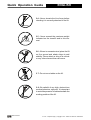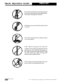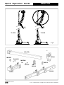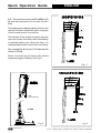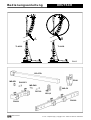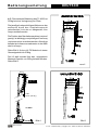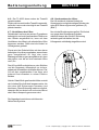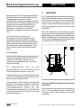
1
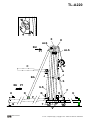
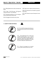
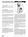
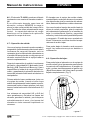
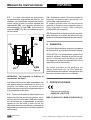
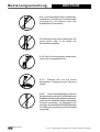
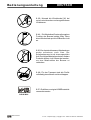
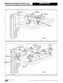
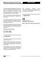
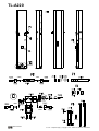
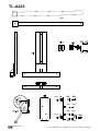
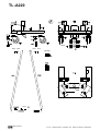
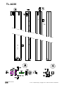
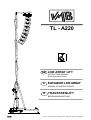
TL - A220
GB LINE ARRAY LIFT
INSTRUCTION MANUAL
Quick Operation Guide
E
ELEVADOR LINE ARRAY
MANUAL DE INSTRUCCIONES
D
TRAVERSENLIFT
BEDIENUNGSANLEITUNG
PRO LIFTS S.L.
V.11.03 - Depósito legal y Copyright 2011. Todos los derechos reservados.
TORRE ELEVADORA
TOWERLIFT
TRAVERSENLIFT
PIED ÉLÉVATEUR
TL-A220
Fabricante - Manufacturer - Hersteller - Fabricant
PRO LIFTS S.L.
Calle 7 final - Pol. Ind. Picassent
E-46220 Picassent (VALENCIA) SPAIN
www.prolifts.es - [email protected]
Este manual de usuario y catálogo anexo de piezas de repuesto es propiedad de PRO LIFTS S.L.
Queda prohibida su reproduccion total o parcial por cualquier medio que la tecnología actual permita.
Depósito legal y Copyright 2008. Todos los derechos reservados.
TL-A220
X
E
ALS
BU
ALS
P1
W
C
J
J
BA
S
BU P1
ILS
F
H
D
B
R
H
P
Q
T
V
PRO LIFTS S.L.
V.11.03 - Depósito legal y Copyright 2011. Todos los derechos reservados.
Quick Operation Guide
CONTENTS
1.
2.
3.
4.
5.
6.
7.
1.
ENGLISH
During the life of this towerlift, it may need spare
parts for maintenance. In this case please
contact your distributor.
Only original spare parts must be used. The
user loses all rights to warranty if any spare
parts other than originals are used or carrys out
any modification or alteration to the towerlift.
Introduction.
Technical Data.
Security.
Instructions.
Maintenance.
Warranty.
Certifications.
For any questions relating to this towerlift
please indicate serial number and year of
production.
INTRODUCTION
Thank you for choosing VMB Towerlifts.
You have acquired a first class, quality product
used by professionals around the world.
2. TECHNICAL IINFORMATION
To be able to work with this tower, lifting and
flying PA and Line Array, please pay special
attention to this manual. Please observe the
technical data and follow all instructions fully
for a correct and safe use.
This manual should also be made available and
remain with the towerlift.
2.2 - Especially designed for lifting and flying
Line array directly from the floor to a height of
5.5m (18’). Able to hang at 50cm (1.6’) from the
main body of the lift.
All VMB towerlifts undergo a strict quality control to guarantee maximum safety and durability.
2.4 - Minimum Load : Can lift or lower without
load.
The TL-A220, has been especially designed
and engineered to hang Line Array to a
maximum height of 5,5 m and a load of 220kg.
This lift is capable of situating the PA 50cm from
the body of the lift.
The benefit of placing the load at a distance
enables the user to achieve the perfect curve
and coverage for the Line array flown.
2.5 - Maximum Height : 5,5 m (18’).
The TL-A220, incorporates the ALS system
(Auto-Lock-Security) and ILS system (InertiaLock-Security) all exclusive to VMB and which
guarantee the load will not fall and provide complete security.
ATTENTION: Do not use this towerlift if you
have not read and understood the instructions.
PRO LIFTS S.L.
2.1 - Towerlift mod. TL-A220
2.3 - Maximum load : 220Kg (485lb). at 50cm
(1.6’) from lift body..
2.6 - Folded Height : 1,72 m (5.6’).
2.7 - Base Surface : 2.1 x 1.6m (6.9 x 5.2’).
2.8 - Transport Weight : 95Kg (209lb).
2.9 - Construction Material : 6082-T6 aluminium
for the main body comprised of 4 profiles and
lifting carriage. DIN 2394 steel for the base and
outriggers. ST-37 steel for the ALS security
system and pulleys.
2.10 - Security Systems: ALS (Auto-LockSecurity), ILS (Inertia-Lock-Security) which
guarantee complete security at all times.
V.11.03 - Depósito legal y Copyright 2011. Todos los derechos reservados.
Quick Operation Guide
ENGLISH
2.11 - 900 kg Manual winch with automatic disc
brake.
2.15 - Spirit level to adjust vertical positioning.
2.16 - All lift elements are finished in polyester
satin black.
2.12 - Cable : DIN 3060 steel. 180 Kg/mm2
quality antitorsion. 5 mm diametre.
2.17 - 360º Wheels for ease of transport to work
place.
2.13 - Adjustable stabilisers on the outriggers
with anti-slip injected rubber base.
2.14 - Outriggers fixed with security locks.
3. SAFETY PRECAUTIONS.
!
3.1 - The TL-A220 is designed for lifing Line
Array and should never be used for elevating
persons.
3.2 - Only situate the lift on hard, flat
surfaces checking that it is in a vertical
position with the spirit level (F) included. If
necessary, adjust with support stabilisers
(Q) by turning the handle (H). Do not use
any other materials to balance the lift.
3.3 - Check all outriggers are inserted
correctly and locked with security locks.
PRO LIFTS S.L.
V.11.03 - Depósito legal y Copyright 2011. Todos los derechos reservados.
Quick Operation Guide
ENGLISH
3.4 - Never elevate the Line Array before
checking it is correctly attached to the lift.
Kgs
3.5 - Never exceed the maximum weight
indicated on the towerlift and in this manual.
3.6 - If there is excessive wind, place the lift
on firm ground and attach slings to add
stability. Never attach a sling to a vehicle
or any other element than can move.
3.7 - Do not use a ladder on the lift.
3.8 - Be carfeful of any high, obstructions
such as balconies, signs etc. It is important
to avoid the presence of cables beneath the
working position of the lift.
PRO LIFTS S.L.
V.11.03 - Depósito legal y Copyright 2011. Todos los derechos reservados.
Quick Operation Guide
ENGLISH
3.9 - Never stand below the raised material
and do not allow others to stand beneath or
around the working area of the lift.
3.10 - Never try to move the lift once the load
is raised.
3.11 - Never use the lift on a mobile surface
or on any vehicle.
3.12 - Before using the lift check the
condition of the cable. The cable should not
be broken or torn. NEVER use defect cables and if in doubt change the cable. Only
use DIN 3060 steel cable 180 Kg/mm2
quality torsion resistant cable.
3.13 - Never remove the handle from the
winch if the lift is elevated with load.
PRO LIFTS S.L.
V.11.03 - Depósito legal y Copyright 2011. Todos los derechos reservados.
Quick Operation Guide
ENGLISH
-25
3.14 - The minimum load for the brake
functioning in the winch is 25kg. Without
this weight the brake will not function.
3.15 - Do not grease or lubricate the break
mechanism in the winch. The break discs
have been especially greased with a
special anti heat, pressure material.
Other products must not be used so as to
avoid the break not working effectively.
3.16 - All profiles must be lowered before
the lift is transported.
3.17 - Only original spares must be used.
O R IG INAL
PRO LIFTS S.L.
V.11.03 - Depósito legal y Copyright 2011. Todos los derechos reservados.
Quick Operation Guide
ENGLISH
4. INSTRUCTIONS.
4.1 - Situate the lift on its transport wheels (T)
upon a flat and stable surface.
When erecting the lift in open air, the risk of
wind is prevalent.
Where wind speeds exceed 30 Km/h it is
essential to tie the lift. 2 lateral eye bolbs (X)
are situated at the top of profile 2, where tensors
should be attached and fixed on secure and firm
ground (NEVER ON A VEHICULE OR
ANYTHING THAT CAN MOVE).
4.2 - Remove the outriggers from their transport
compartments (S) and place them in the working
position (V) ensuring they are fixed with the
security locks (R). The long outriggers are
placed at the front beneath the load. The short
outriggers are placed at the back.
4.3 - Remove the front support bars (BA) from
their transport compartment (S) and place them
in their corresponding fixed position (D) on each
front outrigger and at the top of the first profile
(E) ensuring they are fixed with the pins
provided BU/P1.
To correctly fix the front support bars (BA),
adjust the support of the front outrigger by
turning the stabiliser handel in the necessary
direction.
Insert clips (BU) and security pins (P1).
Adjust the vertical position of the lift with the
stabilisers (Q) turning the handels so that the
spirit level is centred (F).
Support FAS-01 is to be fixed to the forks by
either 1 or 2 points. See fig. 1.
If the Line Array fliyiyng grame has 4 link points
use the FAS-02 support which enables the Line
Array to be flown from 4 points, see fig. 2.
Both supports FAS-01 and FAS-02 are inserted
on the forks as follows:
The Line Array cabinets will be attached to their
fliying grame with the angles calculated
according to the acoustic coverage required.
This ensures the Line Array cabinets can be
curved in function with the necessary degrees
required between them.
The system should be attached at the
necessary distance to achieve the required
curve. The last cabinet should not hit the body
of the lift. See fig. 3.
To ensure the maximum security margin it is
necessarry to always attach the Line Array at
the minimum distance possible from the body
of the lift. This will mean that the bottom cabinet
is as close as possible to the body of the lift.
See fig. 3A.
To avoid overloading do not seperate
uneccessarily the Line Array from the body of
the lift. See fig. 3B.
4.4 - Let go of transport security B, remove the
forks and place them horizontally.
Place the lifting carriage at the required height
so that the Line Array fliying grame can be
attached.
The careful positioning of the front outriggers
enables the Line Array to fit between them and
ease assembley on to the forks.
PRO LIFTS S.L.
V.11.03 - Depósito legal y Copyright 2011. Todos los derechos reservados.
Quick Operation Guide
ENGLISH
FAS-01
GS-0,8
PR-01
Fig. 1
FAS-02
PR-01
GS-0,8
MO-C2
MO-C2
Fig. 2
PRO LIFTS S.L.
V.11.03 - Depósito legal y Copyright 2011. Todos los derechos reservados.
Quick Operation Guide
ENGLISH
A
B
TL-A220
TL-A220
Fig. 3
BC-075L
MR-SP1
PR-01
PAS-SP1
MR-PAS
MO-C2
PAT-02
GS-0,8
FAS-01
PRO LIFTS S.L.
FAS-02
V.11.03 - Depósito legal y Copyright 2011. Todos los derechos reservados.
Quick Operation Guide
ENGLISH
4.5 - The maximum load of the TL-A220 is 220
Kg with the load point at 50 cm from the lift’s
body.
The loading point capacity can be found on the
vertical line which marks the centre of gravity
of the Line Array wich is to be flow.
The situation of the centre of gravity depends
upon the chosen Line Array and is necessary
to calculate before use. Never the less, it is
usually situated at the centre of the Line Array.
See example Fig. 4; 8 Lynx LX-F6 cabinets with
a total of 200 Kg.
Never overload the lift above the stated
maximum weight of 220 Kg. See Fig. 5.
Fig . 5
50 cm
LYNX
LX-F6 (200 Kg.)
TL-A220
Fig. 4
PRO LIFTS S.L.
Fig. 6
V.11.03 - Depósito legal y Copyright 2011. Todos los derechos reservados.
Quick Operation Guide
4.6 - The TL-A220, can also be used as a
conventional towerlift.
If you are using it as a conventional towerlift
always place the load as close to the body as
possible.
4.7 - Elevating the lift:
Once the Line Array is attached to its flying frame
and in the desired position on the forks it is ready
to be lifted to the required height. Turn the winch
handle in a clockwise direction to elevate the
lift.
The lifting carriage will rise first. When it reaches
the top the first section will rise along with the
other sections until the ligt has reached its
maximun height of 5,5 m.
The ILS and ALS enable the lift to automatically
block the carriage and profiles whilst rising
ensuring that it will never fall. The lift, with the
Line array attached will remain fixed at all times.
Once the system is elevated to its required height
gently turn the handle in a clockwise direction.
The security systems will ensure that the load
stays fixed and blocked. The red ALS locks will
be blocked. This enables the cable to be without
any force and means it is only used for the
elevation and descent of the lift.
The following instructions will help you to bring
the system down.
4.8 - Descending the lift:
To bring the lift down you need to first turn the
winch handle slightly clockwise and at the same
time pull out the red ALS lock in (G). (Fig. 7)
This releases the blocking systems. Then turn
the handle anti clockwise, whilst maintaining
the ALS lock pulled out in until the profile has
been completely lowered.
PRO LIFTS S.L.
ENGLISH
G
Fig. 7
All red ALS locks should be pulled out one by
one whilst the handle is turned anti clockwise
and the profiles are brought down, one by one.
If you release your finger from the ALS lock it
will automatically block. In this case, repeat the
first operation by turning slightly clockwise and
then anti clockwise whilst always pulling the red
ALS lock in.
It is necessary to completely lower each profile
before starting to lower the next. If you push
another red ALS lock without having completely
lowered the previous profile the first profile will
remain blocked by the security system and you
will not be able to lower it later.
If this happens, elevate the towerlift to the
locked position and free the lock so that you
can commence the descent again until it is
completely lowered.
Finally, release the carriage lock following the
same principle as before and lower it to the
required level to be able to dismount the Line
Array from the lift.
4.9 - Transport
Once all the profiles are completely lowered
remove the FAS-01 or FAS-02 support and the
forks placing them in their horizontal position
facing down. Lower the carriage so that right
fork can be fixed and blocked for transport (B).
Remove the front support bars ( BA ) by taking
out the pins (BU). Replace the pins in the top
support ( E ) of the lift’s base profile and also
at the top of each front support bar.
V.11.03 - Depósito legal y Copyright 2011. Todos los derechos reservados.
Quick Operation Guide
ENGLISH
Place the bars in their transport compartment.
Remove the outriggers, releasing the locks and
place in their transport position (S). Turn and
tighten the fixing screws (J). The lift can be
transported horizontally by adding the RH-2 kit.
5.3 - All lifts should undergo an annual
technical inspection carried out by an
authorized VMB dealer to check the
certifications and general condition of all the
lift’s elements and security systems involved
in the lift’s use.
5. MAINTENANCE.
5.4 - Only use original spare parts to guarantee
a continued security level.
The user loses all rights to warranty if any spare
parts other than originals are used or carries
out any modification or alteration to the towerlift.
5.1 - Periodically check the condition of the
cable. If a cable is torn or broken it should be
replaced immediately. Do not use the lift if the
cable is not perfect. Only use torsion resistant
steel cable DIN 3060.
5.2 - The lift is supplied completely greased
from the factory. Never the less, we
recommend you periodically grease (depending
on amount used) the teeth of the winch (CD),
end point of the handle (RM), bar (EB) (Fig. 8)
and the profile nylon drums.
EB
EB
5.5 - To request a spare part please indicate
the corresponding code which can be found in
this manual.
6. GUARANTEE.
If the during the guarantee period because of
poor workmanship or faulty materials PRO
LIFTS will repair or replace it. The guarantee
period is at 2 years.This guarantee does not
cover damage caused by improper use, wear
and tear unauthorised repairs. The guarantee
does not cover consumables or defects that
have only a negligible effect on the value or
operation of the elevator tower.
7. CERTIFICATIONS
-
CD
EC Machinery Directive
89/392/ECC and 98/37/ECC
RM
Fig. 8
BGV C1 (GUV-VC1) / BGG 912 (GUV-G912)
ATTENTION: Do not grease or lubricate the
break mechanism.
The brake discs have been greased with a
special heat and pressure resistant grease. Do
not use other products.
PRO LIFTS S.L.
V.11.03 - Depósito legal y Copyright 2011. Todos los derechos reservados.
Manual de instrucciones
ESPAÑOL
CONTENIDO
1.
2.
3.
4.
5.
6.
7.
1.
El elevador, TL-A220, incorpora los sistemas
de seguridad ALS (Automatic-Lock-Security),
ILS (Inertia-Lock-Securyty) exclusivos de VMB,
que garantizan la imposibilidad de caida de
la carga y una total seguridad de utilización.
Introducción
Datos técnicos
Normas de seguridad
Instrucciones de uso
Mantenimiento
Garantía
Certificaciones
ATENCION:
No utilice este elevador sin haber leído y
seguir estas instrucciones. En caso contrario,
podría llegar a provocar un grave accidente.
INTRODUCCION
Estimado usuario:
Agradecemos su confianza al adquirir las
torres elevadoras VMB.
Tiene en sus manos un producto de calidad
y fiabilidad contrastadas por la dilatada
experiencia de los usuarios profesionales
en todo el mundo.
Para poder trabajar con este elevador
volando todo tipo de equipos de sonido sin
peligro y de forma segura, lea atentamente este
manual, observe los datos técnicos y siga
íntegramente todas las instrucciones de
utilización y seguridad.
Este manual de instrucciones, deberá estar
disponible permanentemente junto al elevador.
Todos los elevadores VMB son sometidos a
un constante control de calidad y durísimas
pruebas de verificación, para garantizar la
máxima fiabilidad y resistencia.
El elevador TL-A220, ha sido proyectado
especialmente para levantar hasta 5,5 metros
de altura, equipos de sonido tipo line array con
un peso de 220 Kg desplazados 50 cm. en
avance respecto al cuerpo de la torre.
Este desplazamiento, es necesario para
poder angular los recintos acústicos los
grados precisos para lograr una perfecta
cobertura de sonorización.
Durante la vida útil del elevador, puede
necesitar piezas de repuesto. Diríjase en este
caso a su distribuidor habitual.
Solamente deben utilizarse piezas de repuesto
originales. El usuario perderá todos sus
derechos de garantía si incorpora cualquier
repuesto que no sea original o realiza
cualquier modificación en el elevador.
Para cualquier consulta sobre el elevador,
deberá indicar el número de serie y año de
construcción.
2. DATOS TECNICOS
2.1 - Torre elevadora modelo TL-A220.
2.2 - Diseñada especialmente para levantar
equipos de sonido tipo line array desde el
mismo suelo en sentido vertical a cualquier
altura hasta 5,5 m., con un avance respecto al
cuerpo de la torre de 50 cm.
2.3 - Carga máxima elevable: 220 Kg. desplazada 50 cm del cuerpo del elevador.
2.4 - Carga mínima elevable: Puede subir o
bajar sin carga alguna.
2.5 - Altura máxima: 5,5 m.
2.6 - Altura plegada: 1,72 m. Altura mínima de
carga : 0,05 m.
2.7 - Superficie de la base : Diagonales 2,78
x 2,78 m.
PRO LIFTS S.L.
V.11.03 - Depósito legal y Copyright 2011. Todos los derechos reservados.
Manual de instrucciones
ESPAÑOL
2.8 - Peso de transporte : 95 Kg.
2.12 - Cable : Acero según DIN 3060. Calidad
180 Kg/mm2 antitorsión. Diámetro 6 mm.
2.9 - Material de construcción: Cuerpo principal
de cuatro tramos más carro elevador, en perfil
de aluminio extrusionado 6082-T6. Base,
patas y soportes varios, en perfileria de acero
según DIN 2394. Gatillos de seguridad y
poleas acanaladas en acero ST-37.
2.13 - Platillos estabilizadores ajustables en las
patas, con apoyos antideslizantes de caucho
inyectado.
2.14 - Fijación de las patas con gatillos de
seguridad.
2.10 - Sistemas de fijación y seguridad ALS
(Automatic-Lock-Security), ILS (Inertia-LockSecuryty) que fijan e imposibilitan la caida de
la carga en todo momento exclusivos de VMB,
que garantizan la elevación de todos los tramos
del elevador fiabilizando al máximo su manipulación.
2.15 - Nivel de burbuja para ajustar la posición
vertical de la torre.
2.16 - Todos los elementos del elevador están acabados en poliéster negro satinado.
2.17 - Ruedas direccionables para facilitar el
transporte de la torre en posición vertical y
plegada hasta su emplazamiento de trabajo.
3. NORMAS DE SEGURIDAD.
!
3.1 - El elevador TL-A220 es una máquina
diseñada para la elevación de cargas en
sentido vertical, NUNCA se debe utilizar
como plataforma elevadora de personas.
3.2 - Colocar el elevador sólo en superficies
duras y planas, verificando que está en
posición vertical, mediante el nivel de
burbuja (F) situado en el tramo base.
Ajustar si fuera necesario con los platillos
de apoyo (Q), girando la manivela (H) en
el sentido adecuado. Nunca utilice cuñas
ni elementos extraños para equilibrar el
elevador.
PRO LIFTS S.L.
V.11.03 - Depósito legal y Copyright 2011. Todos los derechos reservados.
Manual de instrucciones
ESPAÑOL
3.3 - Comprobar que las patas están
correctamente montadas y sujetas por sus
pasadores retenedores de seguridad.
3.4 - Nunca se debe elevar una carga
sin antes verificar que está correctamente
apoyada y centrada en los soportes
elevadores adecuados, de forma que el
peso de la carga sólo actúe en sentido
vertical.
Kgs
3.5 - No se debe sobrepasar la capacidad
de carga máxima indicada en la etiqueta
de características del elevador y en este
manual de instrucciones.
3.6 - Si existe posibilidad de viento fuerte o
en ráfagas, coloque el elevador en suelo
firme y asegúrelo con la ayuda de tirantes.
Nunca fije un tirante sobre un vehículo
o cualquier otro elemento que pueda
desplazarse.
3.7 - No use escaleras encima del elevador
ni las apoye en él para realizar ningún tipo
de trabajo.
PRO LIFTS S.L.
V.11.03 - Depósito legal y Copyright 2011. Todos los derechos reservados.
Manual de instrucciones
ESPAÑOL
3.8 - Tenga cuidado con todo tipo de
salientes por encima del elevador como
cornisas, balcones, letreros luminosos, etc...
Es muy importante evitar la presencia de
cables por debajo de la altura de trabajo del
elevador.
3.9 - Nunca se ponga debajo de la carga ni
permita la presencia de otras personas en
la zona de trabajo del elevador.
3.10 - No desplace nunca el elevador si se
encuentra con la carga elevada. No es
aconsejable realizar ningún tipo de
movimiento, ni tan siquiera pequeños
ajustes de posicionamiento.
3.11 - No utilice nunca el elevador sobre
una superficie móvil o vehículo.
3.12 - Antes de utilizar el elevador, verifique
el estado del cable. El cable no debe
presentar rotura de hilos o aplastamiento.
NUNCA use cables defectuosos y en caso
de duda cambie el cable. Sólo utilice cable
de acero según DIN 3060. Calidad 180 Kg/
mm2 resistente a la torsión.
PRO LIFTS S.L.
V.11.03 - Depósito legal y Copyright 2011. Todos los derechos reservados.
Manual de instrucciones
ESPAÑOL
3.13 - Nunca desmonte la manivela del
cabrestante si el elevador está con carga y
elevado.
-25
3.14 - La carga mínima para el funcionamiento del freno del cabrestante sin problemas, es de 25Kg. Sin esta carga mínima el
freno podría no actuar.
3.15 - No engrase ni lubrique el mecanismo
de freno del cabrestante. Los discos de
freno, han sido engrasados con una grasa
especial resistente al calor y la presión.
No deben ser utilizados otros productos
para evitar influir negativamente en el
funcionamiento del freno.
3.16 - Para el transporte del elevador hay
que bajar todos los tramos.
3.17 - Solamente deben utilizarse piezas
de repuesto originales.
O R IG INAL
PRO LIFTS S.L.
V.11.03 - Depósito legal y Copyright 2011. Todos los derechos reservados.
Manual de instrucciones
ESPAÑOL
4. INSTRUCCIONES DE USO.
4.1 - Coloque la torre elevadora apoyada en
sus ruedas de transporte (T) en su emplazamiento de trabajo sobre una superficie plana y
firme.
En el caso de montar el elevador al aire libre,
existe el riesgo que durante su utilización se
genere viento.
A partir de una velocidad del viento de 30 Km/h
es imprescindible arriostrar el elevador, para
lo cual se han previsto dos argollas laterales
de fijación (X) situadas en la parte superior del
segundo tramo, donde deberán fijarse los
tensores que serán anclados a lugares firmes
y seguros (nunca sobre un vehículo o cualquier
otro elemento que pueda desplazarse).
4.2 - Saque las patas de su soporte para
transporte (S) e insértelas a fondo en sus
alojamientos de trabajo (V) comprobando que
quedan sujetas por los gatillos retenedores
(R). Las patas largas delante, bajo la carga y
las cortas detrás .
4.3 - Saque los brazos de apoyo frontales (BA)
del soporte de transporte (S) y colóquelos en
sus puntos de anclaje (D) sobre cada pata
delantera y (E) en los laterales de la parte
superior del tramo base, fijándolos con los
pasadores de seguridad (BU/P1).
Para poder colocar correctamente los brazos
de apoyo frontales (BA), deberá ajustar el apoyo de las patas delanteras, girando adecuadamente las manivelas de los apoyos
regulables de las patas.
Colocar los bulones (BU) y los pasadores de
seguridad (P1).
4.4 - Soltar el seguro de transporte B , sacar
los brazos de carga y volver a colocarlos en posición horizontal.
Colocar el carro elevador a la altura necesaria
para poder fijar el soporte de volado del equipo
de line array.
PRO LIFTS S.L.
La especial disposición de las patas delanteras, permite situar el equipo de sonido en el
suelo justo bajo los brazos de carga.
Sobre los brazos de carga, se colocarán
los soportes FAS-01, en el caso de volar un
equipo con fijación central por uno o dos
puntos de vuelo, fig. 1.
En el caso de que el soporte de volado del
equipo de sonido tenga cuatro anclajes
perimetrales, se utilizarán los soportes FAS02 que permiten suspender los soportes de
volado desde cuatro puntos, ver fig. 2.
Tanto los soportes FAS-01 como los FAS-02
se colocarán sobre los brazos de carga en la
posición y forma que se indica seguidamente:
Los recintos acústicos del equipo de sonido,
se montarán sobre su soporte de volado con
las angulaciones calculadas para la cobertura
acústica requerida.
Esto condiciona que los recintos de line array
se curvarán hacia detrás en función de los
grados necesarios entre ellos.
El equipo deberá colocarse en consecuencia
sobre los brazos de carga del elevador con el
avance necesario para conseguir que esta
curvatura pueda realizarse, sin que la parte
trasera inferior del último recinto tropiece con
el cuerpo del elevador. Ver fig. 3.
Para conseguir el máximo margen de seguridad, es necesario colocar siempre el equipo
de sonido sobre los brazos de carga del
elevador con el avance mínimo posible, de
forma que la parte trasera inferior del último
recinto del equipo line array se encuentre lo
más cerca posible del cuerpo de la torre. Ver
fig. 3A.
No separar innecesariamente el equipo de
sonido del cuerpo de la torre para evitar una
sobrecarga. Ver fig. 3B.
V.11.03 - Depósito legal y Copyright 2011. Todos los derechos reservados.
Manual de instrucciones
ESPAÑOL
FAS-01
FAS-01
GS-0,8
PR-01
Figura 1
FAS-02
PR-01
GS-0,8
MO-C2
MO-C2
Figura 2
PRO LIFTS S.L.
V.11.03 - Depósito legal y Copyright 2011. Todos los derechos reservados.
Manual de instrucciones
ESPAÑOL
A
B
TL-A220
TL-A220
Figura 3
BC-075L
MR-SP1
PR-01
PAS-SP1
MR-PAS
MO-C2
PAT-02
GS-0,8
FAS-01
PRO LIFTS S.L.
FAS-02
V.11.03 - Depósito legal y Copyright 2011. Todos los derechos reservados.
Manual de instrucciones
ESPAÑOL
4.5 - La carga máxima del elevador TL-A220
es de 220 Kg con el punto de aplicación desplazado a 50 cm. del cuerpo del elevador.
El punto de aplicación de la carga se encuentra
en la línea vertical que pasa por el centro de
gravedad del conjunto del equipo de audio a
volar.
La situación del centro de gravedad dependerá
del equipo que se necesite volar y es necesario
determinarlo en cada caso. No obstante, es
habitual que esté situado sobre el centro del
conjunto del equipo. Ver ejemplo de volado de 8
recintos LYNX LX-F6 con un peso total de 200
Kg. Fig 4.
Nunca debe sobrecargarse el elevador por encima de su carga máxima de trabajo de 220 Kg.
Ver no obstante la fig. 5 de cargas y distancias.
La seguridad de trabajo es lo más importante.
Figura 5
50 cm
LYNX
LX-F6 (200 Kg.)
TL-A220
Figura 4
PRO LIFTS S.L.
Figura 6
V.11.03 - Depósito legal y Copyright 2011. Todos los derechos reservados.
Manual de instrucciones
ESPAÑOL
4.6 - El elevador TL-A220, puede ser utilizado
igualmente como una torre elevadora tradicional.
Si se utiliza este elevador como torre de
elevación, coloque SIEMPRE la carga a
elevar lo más cerca posible del cuerpo de la
torre. En todas las torres elevadoras de carga
frontal, la capacidad máxima de carga
disminuye con la distancia de aplicación
respecto al cuerpo de la torre
El elevador con el equipo de sonido volado,
quedará fijado a cualquier altura en el momento
que dejemos de girar la manivela del cabrestante, haciendo imposible su caída o descenso.
4.7 - Operación de subida:
Una vez el equipo de sonido quede montado y
suspendido perfectamente posicionado sobre
los brazos de carga del elevador, solo es
necesario girar la manivela del cabrestante en
el sentido de las agujas de un reloj para que el
elevador comience a subir el equipo hasta su
correcto emplazamiento.
Durante la operación de subida, los sistemas
de fijación y seguridad ALS (Automatic-LockSecurity), ILS (Inertia-Lock-Securyty) fijan e
imposibilitan la caida de la carga en todo momento, garantizando la elevación de todos los
tramos del elevador fiabilizando al máximo su
manipulación.
Primero subirá el carro portabrazos, junto con
el equipo de sonido, cuando el carro haya
subido completamente hasta la parte superior,
comenzará a subir el tramo primero y los otros
tramos, hasta la elevación total máxima de 5,5
metros.
Una vez elevado el equipo de sonido hasta la
altura de volado requerida, girar la manivela
del cabrestante ligeramente en el sentido de
bajar. Los sistemas de fijación y seguridad
actuarán y todo el elevador quedará bloqueado
y asegurado. El cable de acero quedará sin
efecto. Solamente se utiliza durante las operaciones de subir o bajar.
Para poder bajar el elevador, será necesario
seguir las instrucciones que se detallan a
continuación.
4.8 - Operación de bajar:
Para poder bajar el elevador con el equipo de
sonido volado, girar ligeramente presionando
la manivela del cabrestante en el sentido de
subir y pulsar simultáneamente el gatillo rojo
(G) del tramo base o del último tramo que esté
bajado completamente. (Fig. 7)
G
Los sistemas de seguridad ILS y ALS del
carro portabrazos y de todos los tramos del
elevador, permiten su subida, pero bloquean
automáticamente el carro y los tramos del
elevador en todo momento impidiendo su
retroceso.
Figura 7
PRO LIFTS S.L.
V.11.03 - Depósito legal y Copyright 2011. Todos los derechos reservados.
Manual de instrucciones
Esta maniobra permitirá que el gatillo rojo de
seguridad pueda de nuevo pulsarse, liberando
el tramo de la torre, de forma que girando ahora
la manivela del cabrestante en el sentido de
bajar, el elevador bajará normalmente.
Todos los gatillos rojos deberán ser pulsados
conforme los tramos del elevador bajen completamente
Si una vez bajado completamente cualquiera
de los tramos, seguimos girando la manivela
del cabrestante en el sentido de bajar, sin
pulsar el gatillo rojo correspondiente para
liberar el tramo siguiente, el elevador se bloqueará.
En este caso, repetir la operación descrita
inicialmente de subir la torre ligeramente para
liberar el gatillo bloqueado y continuar
bajando de la forma ya descrita.
Es necesario bajar completamente cada
tramo del elevador antes de iniciar la bajada
del tramo siguiente. Si se pulsara otro gatillo
para iniciara la bajada del tramo siguiente, sin
haber bajado completamente el tramo anterior,
el tramo primero quedaría bloqueado por el
sistema de seguridad y no podría bajarse
completamente luego.
Si esto ocurre, se deberá subir de nuevo el
último tramo, liberar el gatillo que permite
bajar el tramo que había quedado bloqueado
y bajarlo completamente, siguiendo, a continuación, el procedimiento de bajar hasta
tener bajados completamente todos los
tramos del elevador.
Liberar por último, el gatillo del carro
portabrazos y bajar el carro, dejándolo a la
altura necesaria para poder desmontar los
recintos acústicos.
PRO LIFTS S.L.
ESPAÑOL
4.9 - Transporte:
Pliegue la torre bajando completamente todos
los tramos. Una vez plegada, retire los soportes
FAS-01 o FAS-02 , saque los brazos de carga
y colóquelos de nuevo en posición vertical
hacia abajo. Baje el carro de forma que el
brazo de carga derecho pueda fijarse con el
pasador de bloqueo para transporte (B).
Desmonte los brazos de apoyo frontales (BA)
quitando los pasadores de seguridad (P1) y los
bulones (BU) de fijación.
Coloque de nuevo los bulones con sus
pasadores de seguridad en los soportes
superiores ( E ) del tramo base de la torre y
en el extremo superior de cada brazo de
apoyo frontal.
Col oq ue l os b ra zo s de a po yo e n su s
al ojamie nt os para transporte
Desmonte las patas liberando los gatillos de
retención (R) y colóquelas en su posición de
transporte (S).
Apriete los pomos de fijación (J)
El elevador puede ser transportado en
posición vertical sobre sus ruedas de
transporte o en sentido horizontal, colocando
el kit de transporte RH-2.
5. MANTENIMIENTO.
5.1 - Compruebe periódicamente el estado del
cable. Si un cable presenta rotura de hilos o
aplastamiento, debe ser sustituido inmediatamente por otro nuevo. No utilice el elevador
con cables en mal estado. Utilice solamente
cable de acero DIN 3060 resistente a la torsión.
V.11.03 - Depósito legal y Copyright 2011. Todos los derechos reservados.
Manual de instrucciones
ESPAÑOL
5.2 - La torre elevadora se suministra
completamente engrasada de fábrica. No
obstante, se recomienda engrasar periódicamente (según el uso) la corona dentada del
cabrestante (CD), los cojinetes del árbol de
accionamiento y el buje (EB), la rosca de la
manivela (RM) (Fig. 8) y los rodillos de nylón
de los tramos.
5.4 - Solamente deben utilizarse piezas de
repuesto originales para garantizar una
continuada seguridad de uso.
El usuario pierde todos los derechos de
garantía si incorpora otros repuestos que no
sean originales o lleva a cabo cualquier
modificación en el aparato.
5.5 - Para solicitar cualquier pieza de repuesto,
debe indicarse su número de referencia, que
figura en las hojas de despiece de este manual.
EB
6. GARANTIA.
EB
El periodo de garantía de esta torre elevadora
es de dos años, a partir de la fecha de compra.
PRO LIFTS S.L. se compromete, a partir de la
fecha de compra y durante el periodo de garantía, a eliminar todos los fallos que puedan aparecer producidos por defectos de los
materiales o de la fabricación.
CD
RM
No e st án i nclu id os e n la g ar an tí a lo s
daños producidos por un uso indebido,
modificaciones del producto, manipulación por
terceros o siniestro natural o accidental.
Figura 8
ATENCION: No engrasar ni lubricar el
mecanismo del freno.
Los discos de freno han sido engrasados con
una grasa especial resistente al calor y la
presión. No deben ser utilizados otros
productos para evitar influir negativamente en
el funcionamiento del freno.
5.3 - Todos los elevadores deben pasar una
inspección técnica anual como mínimo, en un
servicio técnico autorizado VMB para validar
las certificaciones, comprobando el perfecto
estado de uso de todos y cada uno de los
diferentes elementos mecánicos y sistemas de
seguridad que intervienen en el funcionamiento
del elevador.
PRO LIFTS S.L.
7. CERTIFICACIONES
Directiva de maquinas:
89/392/CE y 98/37/CE
BGV C1 (GUV-VC1) / BGG 912 (GUV-G912)
V.11.03 - Depósito legal y Copyright 2011. Todos los derechos reservados.
Bedienungsanleitung
DEUTSCH
INHALTSVERZEICHNIS
1.
2.
3.
4.
5.
6.
7.
ACHTUNG: Benutzen Sie diesen Towerlift
nicht ohne vorher die Anweisungen gelesen
und verstanden zu haben.
Einführung.
Technische Daten.
Sicherheitsmaßnahmen.
Bedienungsanleitung.
Wartung.
Garantie.
Zertifikate.
1. EINFÜHRUNG
Danke, dass Sie sich für einen VMB Towerlift
entschieden haben. Sie haben ein qualitativ
erstklassiges Produkt erworben, welches von
Profis auf der ganzen Welt genutzt wird.
Um mit diesem Towerlift PA und Line Arrays
Heben und Fliegen zu können beachten Sie
bitte die folgende Bedienungsanleitung.
Beachten Sie die technischen Daten und
befolgen Sie alle Instruktionen für den
richtigen und sicheren Gebrauch.
Diese Gebrauchsanweisung sollte jederzeit
zugänglich sein und bei dem Towerlift
aufbewahrt werden.
Der Towerlift kann während seiner Lebenszeit
Ersatzteile für die Wartung benötigen.
Kontaktieren Sie in diesem Fall bitte Ihren
Lieferanten.
Es dürfen nur original Ersatzteile verwendet
werden. Die Garantie geht verloren, wenn
keine Originalteile verwendet werden, oder
eine Veränderung am Towerlift vorgenommen
wird.
Bei allen Fragen, die diesen Towerlift
betreffen, bitte die Seriennummer und das
Produktionsjahr angeben.
2. TECHNISCHE INFORMATIONEN
2.1 - Towerlift Typ TL-A220
2.2 - Speziell entwickelt zum Heben und Fliegen
von Line Array direkt vom Boden bis in eine
Höhe von 5,5m. Geeignet, um Lasten 50cm
vorgelagert zu hängen.
Alle VMB Towerlifte unterliegen einer strikten
Qualitätskontrolle um maximale Sicherheit und
Leistungsfähigkeit zu gewährleisen.
Der TL-A220 wurde speziell konzipiert und
technisiert, um Line Arrays mit einem Gewicht
von 220kg bis zu einer maximalen Höhe von
5,5m zu hängen. Der Lift ist dazu geeignet,
eine PA 50cm vorgelagert anzubringen.
Der Nutzer zieht beim Vorlagern der Last den
Vorteil, dass er Winkel und Reichweite eines
Line Arrays optimal ausrichten kann.
2.3 - Maximale Hubkraft: 220kg bei einer
Vorlagerung von 50cm.
2.4 - Minimale Last: kann ohne Last Heben und
Senken.
2.5 - Maximale Höhe: 5,5m.
2.6 - Transporthöhe: 1,72m.
2.7 - Grundfläche: Diagonal 2,78 x 2,78m.
2.8 - Transportgewicht: 95kg.
Der TL-A220 ist mit dem ALS System (AutoLock-Security) und ILS System (Inertia-LockSecurity) ausgestattet, alle von VMB
patentiert. Sie schützen die Last vor dem Fall
und garantieren lückenlose Sicherheit.
PRO LIFTS S.L.
2.9 - Werkstoffe: 6082-T6 Aluminium für das
Hauptgerüst, bestehend aus 4 Profilen und
Hubgestell. DIN 2394 Stahl für das
Basisplatte und die Auslegerfüße. ST-37
Stahl für das ALS Sicherheits-System und
die Umlenkrolle.
V.11.03 - Depósito legal y Copyright 2011. Todos los derechos reservados.
Bedienungsanleitung
DEUTSCH
2.10 - Sicherheits-Systeme: ALS (Auto-LockSecurity), ILS (Inertia-Lock-Security), welche
lückenlose Sicherheit zu jeder Zeit
garantieren.
2.15 - Wasserwaage zum Einstellen der
senkrechten Turmlage.
2.11 - 900kg handbetriebene Seilwinde mit
automatischer Lasthaltebremse.
2.12 - Seil: DIN 3060 Stahl. 180kg/mm²
verwindungssteife Qualität. 5mm
Durchmesser.
2.16 - Alle Lift-Elemente sind in Polyester-SatinBlack lackiert.
2.17 - 360° Rollen für den einfachen Transport
zum Einsatzort.
2.13 - Verstellbare Stabilisatoren an den
Auslegern mit anti-rutsch beschichteter
Gummisohle.
2.14 - Ausleger werden mit Sicherheits-Klinken
fixiert.
3. SICHERHEITSVORKEHRUNGEN
!
3.1 - Der TL-A220 ist speziell für Line Array
entwickelt worden und sollte niemals zum
Heben von Personen genutzt werden.
3.2 - Den Lift nur auf harten und ebenen
Flächen aufstellen und anhand der
Wasserwaage (F) vertikal ausrichten. Bei
Bedarf mittels des Stelltellers (Q) durch
Drehen der Spindelkurbel (H) in
entsprechender Richtung die Turmlage
einstellen.
PRO LIFTS S.L.
V.11.03 - Depósito legal y Copyright 2011. Todos los derechos reservados.
Bedienungsanleitung
DEUTSCH
3.3 - Achten Sie bitte darauf, dass die
Ausleger vollkommen eingeschoben und
mittels der Sicherheitsbolzen befestigt sind.
3.4 - Niemals das Line Array anheben,
bevor nicht sichergestellt ist, dass es korrekt
am Lift befestigt ist.
Kgs
3.5 - Niemals, das am Towerlift und in
dieser Anleitung vorgegebene MaximalGewicht überschreiten.
3.6 - Bei stärkerem Wind den Turm auf
festes Boden stellen und mittels Seilanker
gegen die Windbelastung schützen. Niemals
die Seilanker an einem Fahrzeug oder einem
anderen beweglichen Gegenstand
befestigen.
3.7 - Niemals eine Leiter auf, bzw. an dem
Lift verwenden.
PRO LIFTS S.L.
V.11.03 - Depósito legal y Copyright 2011. Todos los derechos reservados.
Bedienungsanleitung
DEUTSCH
3.8 - Vorsicht bei jeder Höhe: Hindernisse,
wie Balkone, Schilder etc. Es ist wichtig die
Verwendung von Kabeln nahe der
Arbeitsfläche zu vermeiden.
3.9 - Niemals unter dem ausfahrenden Lift
sowie neben oder in der Nähe der
Arbeitsfläche aufhalten.
3.10 - Den Lift nicht bewegen, wenn dieser
unter Last und ausgefahren ist.
3.11 - Niemals den Lift auf einem
beweglichen Untergrund oder Fahrzeug
nutzen.
3.12 - Vor der Verwendung des Lifts den
Seilzustand kontrollieren. Das Seil darf keine
Drahtbrüche bzw. Quetschstellen aufweisen.
Unter keinen Umständen Seile in schlechtem
Zustand verwenden. Im Zweifelsfall Seil
tauschen. Ausschließlich DIN 3060 Stahlseile
mit 180kg/mm² verwindungs-steifer Qualität
verwenden.
PRO LIFTS S.L.
V.11.03 - Depósito legal y Copyright 2011. Todos los derechos reservados.
Bedienungsanleitung
DEUTSCH
3.13 - Niemals die Windekurbel (W) bei
unter Last stehendem und ausgefahrenem
Lift abbauen.
-25
3.14 - Die Mindestlast für eine reibungslose
Funktion der Bremse beträgt 25kg. Ohne
diese Mindestlast spricht die Bremse nicht
an.
3.15 - Den Lastdruckbremsen-Mechanismus
weder schmieren noch ölen. Die
Scheibenbremse ist mit einem speziellen
Anti-Druckhitze Material geschmiert. Andere
Produkte dürfen nicht verwendet werden,
um eine Missfunktion der Bremse zu
verhindern.
3.16 - Für den Transport sind alle Profile
vollständig einzufahren und einzuklappen.
3.17 - Es dürfen nur original VMB Ersatzteile
verwendet werden.
O R IG INAL
PRO LIFTS S.L.
V.11.03 - Depósito legal y Copyright 2011. Todos los derechos reservados.
Bedienungsanleitung
DEUTSCH
4. BEDIENUNGSANLEITUNG
4.1 - Den Towerlift auf den Transportrollen (T)
abgestützt auf einer ebenen und festen
Arbeitsfläche aufstellen.
Bei Freiluftanwendungen ist die Gefahr von
W ind vorherrschen. Übersteigt die
Windgeschwindigkeit 30kmh ist es notwendig
den Lift mit Seilen zu sichern. Zwei Fixierpunkte
(X) sind seitlich oben am 2. Profil angebracht,
an denen die Zugseile befestigt und auf festem
Boden gesichert werden sollten (Niemals an
einem Fahrzeug oder einem anderen
beweglichen Gegenstand).
4.2 - Die Ausleger aus der Transporthalterung
(S) herausnehmen und in deren
Arbeitsaufnahmen (V) voll einschieben. Dabei
achten Sie bitte darauf, dass sie mittels der
Sicherheitsbolzen (R) befestigt sind. Die langen
Ausleger werden vorne neben der Last, die
kurzen Ausleger auf der Rückseite angebracht.
4.3 - Die Frontlaststützen (BA) aus der
Transporthalterung (S) nehmen und in die feste
Arbeitsposition auf dem jeweiligen Ausleger und
am oberen Ende des 1. Profils bringen (D).
Mittels der Sicherheitsbolzen (BU/P1)
befestigen. Um die Frontlaststützen (BA) richtig
zu befestigen, richten Sie den Lift durch Drehen
der Kurbeln an den Stelltellern (Q) der Ausleger
in die entsprechende Richtung, aus.
Mit Splint (BU) u. Bolzen (P1) sichern.
Die senkrechte Liftlage über die verstellbaren
Stellteller (Q) durch Drehen der Kurbel (H) zum
Zentrieren der Wasserwaagenblase (F) an der
Kreismitte einstellen.
4.4 - Die Transportsicherungsbolzen (B) der
Gabelaufnahmen (C) entfernen und in
horizontale Position bringen. Die Lastgabeln in
der gewünschten Höhe positionieren, um den
Line Array Flugrahmen zu montieren.
PRO LIFTS S.L.
Die Position der vorderen Ausleger, macht es
möglich das Line Array mittig unter den
Flugrahmen zu setzen. Dieses erleichtert die
Montage an den Gabeln.
Die Aufnahme FAS-01 wird an den Gabeln an
entweder 1 oder 2 Punkten befestigt. Siehe Bild
1.
Hat der Flugrahmen 4 Verbindungspunkte, wird
die Aufnahme FAS-02 verwendet, um das Line
Array aufzuhängen. Siehe Bild 2.
FAS-01 und FAS-02 werden wie folgt an den
Gabeln befestigt:
Die Line Array Module werden mit dem
Flugrahmen verbunden, während die Winkel
sind bereits anhand der akustischen
Gegebenheiten errechnet worden sind.
Dieses stellt sicher, dass die Line Array Module
während des Liftens im richtigen Winkel
zueinander eingestellt werden können.
Das System sollte im richtigen Abstand für die
erforderliche Neigung angebracht sein. Das
unterste Modul sollte nicht den Lift berühren.
Siehe Bild 3.
Um die maximale Sicherheit zu gewährleisten,
ist es nötig, das Line Array immer mit dem
geringst möglichen Abstand zum Lift zu
befestigen. Das heißt, dass das unterste Modul
so nah wie möglich am Lift positioniert ist. Siehe
Bild 3A. Zum Schutz vor Überladung sollte das
Line Array keinen unnötigen Abstand zum Lift
haben. Siehe Bild 3B.
V.11.03 - Depósito legal y Copyright 2011. Todos los derechos reservados.
Bedienungsanleitung
DEUTSCH
FAS-01
FAS-01
GS-0,8
PR-01
Bild 1
FAS-02
PR-01
GS-0,8
MO-C2
MO-C2
Bild 2
PRO LIFTS S.L.
V.11.03 - Depósito legal y Copyright 2011. Todos los derechos reservados.
Bedienungsanleitung
DEUTSCH
A
B
TL-A220
TL-A220
Bild 3
BC-075L
MR-SP1
PR-01
PAS-SP1
MR-PAS
MO-C2
PAT-02
GS-0,8
FAS-01
PRO LIFTS S.L.
FAS-02
V.11.03 - Depósito legal y Copyright 2011. Todos los derechos reservados.
Bedienungsanleitung
DEUTSCH
4.5 - Die maximale Belastung des TL-A220 ist
220kg bei einer Vorlagerung von 50cm.
Die jeweilige Ladepunkt Kapazität kann an der
senkrecht durch den Gravitationspunkt
verlaufenden Linie des zu hängenden Line
Arrays ermittelt werden.
Die Position des Gravitationspunktes (centre of
gravity) ist abhängig vom jeweiligen Line Array
und muss vorher errechnet werden. Allerdings
befindet sich dieser normalerweise in der Mitte
des Line Arrays.
Siehe Bild 4; 8x Lynx LX-F6 Module mit einem
Gesamtgewicht von 200kg.
Der Lift darf niemals über das angegebene
Maximal-Gewicht von 220kg beladen werden.
Siehe Bild 5.
Bild 5
50 cm
LYNX
LX-F6 (200 Kg.)
TL-A220
Bild 4
PRO LIFTS S.L.
Bild 6
V.11.03 - Depósito legal y Copyright 2011. Todos los derechos reservados.
Bedienungsanleitung
DEUTSCH
4.6 - Der TL-A220 kann zudem als Towerlift
genutzt werden.
Wird er als konventioneller Towerlift verwendet,
sollte die Last so nah wie möglich am Towerlift
platziert werden.
4.8 - Herabsenken des Liftes:
Der Lift wird durch leichtes Kurbeln im
Uhrzeigersinn und gleichzeitiges Drücken der
roten ALS Sicherung herunter gefahren (G).
(Bild 7)
4.7 - Hochfahren des Liftes:
Sobald das Line Array an seinem Flugrahmen
befestigt ist und in der gewünschten Position an
den Gabeln angebracht ist, kann mit dem
Hochfahren des Liftes in die erforderliche Höhe
begonnen werden. Dafür wird die Kurbel im
Uhrzeigersinn gedreht.
Nun ist das Blockiersystem gelöst. Die Kurbel
nun gegen den Uhrzeigersinn drehen,
während dessen die rote ALS Sicherung
weiterhin gedrückt halten, bis alle
Liftsegmente vollständig eingefahren sind.
Zuerst wird der Gabelschlitten mit dem daran
befestigten Line Array angehoben, wenn dieses
ganz ausgefahren ist folgt das erste
Mastsegment bis es ganz ausgefahren ist, dann
das zweite, usw. bis auf eine maximale Höhe
von 5,5m.
G
Das ILS und ALS ermöglichen es, den Schlitten
und die Segmente automatisch zu sichern,
sodass sie keinesfalls zurückfallen können. Der
Lift mit dem angebrachten Line Array wird
jederzeit fest verankert in seiner Position
bleiben.
Hat der Gabellift die gewünschte Höhe erreicht
wird, drehen Sie die Kurbel langsam weiter, bis
die roten ALS Sicherungen einrasten und
blockieren. Diese Sicherung macht es möglich,
dass das Seil nur beim hoch und runter fahren
des Liftes in Anspruch genommen wird.
Bild 7
Die folgenden Instruktionen schildern den
Abbau des Systems.
PRO LIFTS S.L.
V.11.03 - Depósito legal y Copyright 2011. Todos los derechos reservados.
Bedienungsanleitung
DEUTSCH
5.
Sobald die ALS Sicherung losgelassen wird,
blockiert die Sicherung automatisch wieder.
Die Mastsegmente müssen einzeln
nacheinander vollständig eingefahren werden,
bevor das nächste Segment eingefahren wird.
Wird bereits eine andere ALS Sicherung
gedrückt, als die des herunterfahrenden
Segmentes, wird dieses an der Stelle
blockieren und später nicht weiter einzufahren
sein.
Tritt dieser Fall ein, muss bis zum
Blockierpunkt wieder hochgefahren und
anschließend erneut eingefahren werden.
Zuletzt wird die Sicherung des Lastschlittens
gelöst, genau wie zuvor beschrieben und zu
der gewünschten Höhe hinabgesenkt, in der
das Line Array vom Lift demontiert werden
kann.
WARTUNG
5.1 - Regelmäßig den Seilzustand kontrollieren.
Weist ein Seil Drahtbrüche bzw. Quetschungen
auf, ist es sofort durch ein Neues zu ersetzen.
Unter keinen Umständen den Hebeturm mit
Seilen in schlechtem Zustand verwenden. Nur
verwindungssteifes Stahlseil nach DIN 3060
verwenden.
5.2 - Der Hebeturm wird werkseitig komplett
geschmiert geliefert. Es wird jedoch empfohlen,
regelmäßig ( je nach Bedarf ) das Zahnrad der
Winde, die Wälzlager der Antriebswelle und die
Hülse, das Kurbelgewinde und die Abschnitte
zu schmieren (CD, RM, EB ) (Bild 8).
4.9. Transport
Nachdem alle Mastsegmente abgesenkt sind,
werden die Aufnahme FAS-01 oder FAS-02
entfernt und die Gabeln werden in ihrer
horizontalen Ausgangsposition, nach unten
zeigend, befestigt.
Der Gabelschlitten wird so weit
heruntergefahren, bis die Gabeln für den
Transport gesichert werden können (B).
Die Bolzen (BU) an den Frontlaststützen lösen
und die Frontlaststützen (BA) entfernen. Die
Bolzen wieder einsetzen (E/D).
Die Laststützen in den Transportvorrichtungen
platzieren. Die Ausleger entfernen, indem die
Sicherungen gelöst werden, und in der
Transporthalterung sichern (S). Die
Fixierschrauben fest anziehen (J). Der Lift kann
mit dem optionalen RH-2 Kit auch horizontal
transportiert werden.
PRO LIFTS S.L.
Achtung: Die Bremsscheiben nicht einölen
oder fetten.
Die Scheibenbremsen sind mit einer speziellen
hitze- und druckbeständigen Schmierung
versehen. Bitte keine anderen Produkte
verwenden.
V.11.03 - Depósito legal y Copyright 2011. Todos los derechos reservados.
Bedienungsanleitung
DEUTSCH
5.3 - Alle Lifte sollten mindestens einmal jährlich
von einer Fachkraft inspeziert werden, um den
generellen Zustand aller für den Gebrauch des
Lifts
relevanten
Elemente
und
Sicherheitssysteme des Lifts zu überprüfen und
die Zertifizierungen aufrecht zu erhalten.
Die
Garantie
umfasst
keine
Verbrauchsmaterialien und Mängel, die den
Wert oder die Gebrauchstauglichkeit nur
unerheblich beeinträchtigen.
5.4 - Für eine kontinuierliche Betriebssicherheit
sind ausschließlich Original - Ersatzteile zu
verwenden.
7. ZERTIFIKAT
Alle Gewährleistungsansprüche sind für den
Anwender aufgehoben, wenn er Nicht- OriginalErsatzteile verwendet bzw. Änderungen am
Produkt selbst vornimmt.
Maschinenrichtlinie
89/392/ECC und 98/37/ECC
BGV C1 (GUV-VC1) / BGG 912 (GUV-G912)
5.5 - Für die Bestellung von Ersatzteilen ist stets
dessen Bestellnummer anzugeben, welche den
Stücklisten-Blättern dieser Anleitung zu
entnehmen ist.
VMB Service Deutschland:
Tel : 04442 - 92900
Fax: 04442 - 929090
6. GARANTIE
Die Hersteller - Garantiezeit des Lifts beträgt 2
Jahre ab Kaufdatum.
PRO LIFTS S.L. verspricht alle material oder
herstellungsbedingten Mängel innerhalb der
Garantiezeit durch Reparatur order Austausch
zu beseitigen.
In Europa gilt eine Garantiezeit von 24 Monaten.
Von der Garantie ausgenommen sind Schäden
aufgrund von unsachgemäßem Gebrauch,
Verschleiß oder Eingriffen Dritter.
PRO LIFTS S.L.
V.11.03 - Depósito legal y Copyright 2011. Todos los derechos reservados.
TL-A220
7040L
PRO LIFTS S.L.
V.11.03 - Depósito legal y Copyright 2011. Todos los derechos reservados.
TL-A220
5425
PRO LIFTS S.L.
V.11.03 - Depósito legal y Copyright 2011. Todos los derechos reservados.
TL-A220
2044
7039
5459
5457
5458
2044
2044
7061
7061
7240
PRO LIFTS S.L.
V.11.03 - Depósito legal y Copyright 2011. Todos los derechos reservados.
TL-A220
7061
7061
7061
7061
7248
PRO LIFTS S.L.
V.11.03 - Depósito legal y Copyright 2011. Todos los derechos reservados.
TL-A220
7040L
7078
7061
2044
7061
2044
7061
2044
7078
PRO LIFTS S.L.
V.11.03 - Depósito legal y Copyright 2011. Todos los derechos reservados.
TL-A220
2044
2044 7061
7061 2044
7061
MR-PAS
PAT-02
6409
7078
PRO LIFTS S.L.
V.11.03 - Depósito legal y Copyright 2011. Todos los derechos reservados.
TL-A220
7287
PRO LIFTS S.L.
V.11.03 - Depósito legal y Copyright 2011. Todos los derechos reservados.
TL-A220
PRO LIFTS S.L.
V.11.03 - Depósito legal y Copyright 2011. Todos los derechos reservados.
LISTA DE PIEZAS TL-A220 / SPARE PARTS LIST
Ref.
Descripción / Description :
2026
2029
2030
2037
2044
2046
2047
2048
2049
2050
2140
2152
2160-CO
2161
Gatillo seguridad / Safety catch.
Pomo baquelita patas / Crank nob
Platillo de apoyo patas / Stabilizer round plate
Tornillo M-10 / M-10 screw
Tuerca M-10 / M-10 nut
Tuerca M-5 / M-5 nut
Arandela M-12 / M-12 Washer.
Arandela M-6 / M-6 washer
Tornillo M-6 / M-6 screw
Tornillo M-5 / M-5 screw
Tuerca M12 / M-12 nut
Arandela M-8 / M-8 washer
Cabrestante
Manivela patas / Steel hand crank
2170
5415
5416
5418
5419
5420
5421
5425
5429
5430
5432
5433
5434
5435
5436
5441
5442
5443
5444
5445
5446
5447
5448
5449
5455
5457
5458
5459
5460
5461
5462
5462S
5465
5466
Pomo con rosca M-8 / M-8 knob screw.
Polea special / Special pulley
Eje de acero / Steel axe
Tope de aluminio / Alluminium piece
Tope de aluminio / Alluminium piece
Tope de aluminio / Alluminium piece
Tope de aluminio / Alluminium piece
Cable
Rueda / Wheel
Tornillo M-14 / M-14 screw
Tornillo M-8 / M-8 screw
Tornillo M-6 / M-6 screw
Fijación cable / Cable fixation
Tornillo M-8x25 / M-8x25 Screw.
Tornillo M-8 / M-8 screw
Tramo 1 base / Profile section 1
Tramo 2 / Profile section 2
Tramo 3 / Profile section 3
Tramo 4 / Profile section 4
Carro elevador / Lifting carriage
Base
Soporte brazos de carga / Fork support
Portapatas / Outrigger support
Portacabrestante / Winch plate
Sporte rodillos carro / Carriage pulley support
Pata larga derecha completa / Complete long right outrigger
Pata larga izquierda completa / Complete long left outrigger
Pata corta completa / Complete short outrigger
Apoyo frontal patas / Legs profile strut
Sujeción tirante / Support bar holder
Gatillo ALS / ALS catch
Fijación gatillo / catch suport
Pletina / support
Sujeción tirante / support bar holder
LISTA DE PIEZAS TL-A220 / SPARE PARTS LIST
Ref.
Descripción / Description :
6409
7039
7040L
7061
7078
7208
Nivel de burbuja / Spirit level
Estabilizador completo / Complete stabilizer
Brazo de carga negro largo / load support long fork
Arandela M-10 / M-10 washer
Tuerca M-8 / M-8 nut
Tornillo M-8 / M-8 screw
7209
Tirante sujección base / Base profile strut
7209D
7222
7223
Tirante sujección base / Base profile strut
Tornillo especial / Special screw
Polea nylon / Nylon pulley
7232
Tornillo especial polea / Special pulley screw
7234
Tornillo M-8 / M-8 screw
7240
Tornillo M-10 / M-10 screw
7242
Arandela M-14 / M-14 Washer
7243
Tuerca M-14 / M-14 Nut
7244
Varilla freno inercia / Brake lock
7245
Soporte varilla freno inercia / Brake lock support
7246
Perno roscado / Screw
7247
7248
7254
7287
7424
7962
Tornillo M-5 / M-5 Screw
Muelle freno inercia / Brake spring
Tornillo M-10 / M-10 screw
Tope aluminio / Aluminium stop
Tornillo / Screw
Tornillo M-12 / M-12 Nut
MR-SPI
Pasador de seguridad / Ring safety pin
PAS-SPI
MR-PAS
PAT-02
Pasador de acero / Fasterner steel pin
Pasador R / R clips
Pasador de acero / Fastener steel pin