1
MANUAL DE INSTRUCCIONES
USER’S MANUAL
MEDIDOR L/C/R CON PANTALLA DUAL
DUAL DISPLAY L/C/R METER
MZ-505C
- 0 MI1972 -
NOTAS SOBRE SEGURIDAD
Antes de manipular el equipo leer el manual de instrucciones y muy
especialmente el apartado PRESCRIPCIONES DE SEGURIDAD.
El símbolo
sobre el equipo significa "CONSULTAR EL
MANUAL DE INSTRUCCIONES". En este manual puede aparecer
también como símbolo de advertencia o precaución.
Recuadros de ADVERTENCIAS Y PRECAUCIONES pueden
aparecer a lo largo de este manual para evitar riesgos de accidentes
a personas o daños al equipo u otras propiedades.
SAFETY NOTES
Read the instruction manual before using the equipment, mainly
"SAFETY RULES" paragraph.
The symbol
on the equipment means "SEE USER’S
MANUAL". In this manual may also appear as a Caution or Warning
symbol.
Warning and Caution statements may appear in this manual to
avoid injury hazard or damage to this product or other property.
SUMARIO
CONTENTS
) Manual español ...............................................................
) English manual................................................................
Manual de instrucciones. MZ-505C
ÍNDICE
1 GENERAL .....................................................................................1
1.1 Introducción.........................................................................1
1.2 Especificaciones .................................................................2
2 PRESCRIPCIONES DE SEGURIDAD..........................................7
3 INSTRUCCIONES DE MANEJO...................................................9
3.1 Descripción de los mandos y elementos.............................9
3.2 Mensajes de la Pantalla LCD............................................11
3.2.1 Indicadores especiales ................................................13
3.3 Cómo operar .....................................................................13
3.3.1 Medición de inductancia..............................................13
3.3.2 Medición de capacidad................................................14
3.3.3 Medición de resistencia ...............................................16
4 INSTRUCCIONES DE OPERACIÓN ..........................................17
4.1 Apagado Automático.........................................................17
4.1.1 Medición Continua.......................................................17
4.1.2 Interruptor de Encendido. ............................................17
4.2 Selección de FRECUENCIA .............................................18
4.3 Modo SERIE / PARALELO ...............................................18
4.4 Botón ESCALA (RANGE) .................................................18
4.5 Tecla de función L/C/R (Sólo en indicador principal)........19
4.6 Tecla de función Q/D/R (Sólo en indicador secundario)...19
4.7 HOLD >2 SEGUNDOS .....................................................19
4.8 BOTONES MIN / MAX ......................................................20
4.9 AJUSTES ..........................................................................21
4.10 REL Modo Relativo (sólo en la pantalla principal) ............24
4.11 LÍMITES HI / LO (Superior / Inferior).................................25
4.12 TOL ...................................................................................25
4.13 Detección automática del estado del fusible.....................26
4.14 Calibración ........................................................................27
4.15 Indicador de pila descargada ............................................28
Manual de instrucciones. MZ-505C
5 MANTENIMIENTO ......................................................................29
5.1 Mantenimiento...................................................................29
5.2 Sustitución de la pila .........................................................29
5.3 Sustitución del fusible .......................................................30
5.4 Recomendaciones de limpieza .........................................32
Manual de instrucciones. MZ-505C
MEDIDOR L/C/R CON PANTALLA DUAL
MZ-505C
1 GENERAL
1.1 Introducción
Este medidor de L/C/R portátil permite cuentas de hasta 19.999
con 4 ½ dígitos controlado mediante un microprocesador especial
para la realización de medidas de inductancia, capacidad y
resistencia. Su operación es simple, permite efectuar mediciones en
modo paralelo y en modo serie. El medidor proporciona medidas
directas y precisas para bobinas, condensadores y resistencias en
diferentes frecuencias de operación. Permite la selección de las
escalas de forma tanto manual como automática.
Las teclas del panel frontal proporcionan máxima comodidad en
la selección de funciones y características, como la memoria de
lectura; registro de valores máximo, mínimo y promedio; medidas
relativas; tolerancia para clasificación de componentes; frecuencia y
selección L/C/R.
Los resultados de las medidas pueden ser transmitidos a un PC
mediante una interfaz RS232C optó acoplada.
Un soporte inclinado proporciona flexibilidad de visión y
operación. La caja fabricada en plástico y goma protege al medidor
y le proporciona resistencia mecánica. Para su operación requiere
una única pila de 9 V, y también permite la utilización alternativa de
un adaptador de alimentación de 12 V.
04/2015
Página 1
Manual de instrucciones. MZ-505C
1.2 Especificaciones
Parámetros medibles
Pantallas
L/C/R
Q/D/R
Rangos de Medición
C (120 Hz)
C (1 kHz)
L (120 Hz)
L (1 kHz)
R
Resolución
R
L
C
Modalidad de escala
Terminales de medida
Frecuencias de prueba
Modo tolerancia
Régimen de medición
Tiempo de respuesta
Autodesconexión
Página 2
LS + (Q, D, RS), LP + (Q, D, RP), CS
+ (Q, D, RS), CP + (Q, D, RP).
Visualización
máxima
19999
cuentas 4 ½ dígitos.
Visualización máxima 999,9 cuentas
4 dígitos (Autorrango).
1 pF ~ 10 mF (precisión
0,7 %).
0,1 pF ~ 1000 μF (precisión
0,7 %).
1 μH ~ 10000 H (precisión
0,7 %).
0,1 μH ~ 1000 H (precision
0,7 %).
1 mΩ ~ 10 MHΩ (precisión
0,5 %).
básica
básica
básica
básica
básica
Hasta 0,001 Ω.
Hasta 0,1 μH.
Hasta 0,1 pF.
Auto y manual.
2 terminales con zócalo.
1 KHz, 120 Hz.
1 %, 5 %, 10 %, 20 %.
1 medición x segundo, nominal.
Aprox. 1 segundo en la escala
manual.
A los 10 minutos aprox. Sin
operación.
04/2015
Manual de instrucciones. MZ-505C
Coeficiente temperatura
0,15 x (precisión específica) / °C
(0-18 °C y 28-40 °C).
Indicador de pila agotada
El símbolo
pantalla.
600 mV AC.
Fusible.
Voltaje de medida
Protección de entrada
Alimentación
Interna
Externa
Consumo
- +
aparece en la
Pila 9V IEC6F22.
12 a 15 V DC.
Aproximadamente 12 mA en
funcionamiento.
0,03 mA después de la
autodesconexión.
Condiciones ambientales de funcionamiento
Altitud
Hasta 2000 m.
Margen de temperaturas
De 0 a 50 °C.
Humedad relativa máxima 80% (hasta 31°C).
decreciendo linealmente hasta el
50 % a 40 °C.
Características mecánicas
Dimensiones
Peso
A. 91 x Al. 192 x Pr. 52,5 (mm).
Aproximadamente 365 gr. (incluido
accesorios).
Accesorios incluidos
Pinzas cocodrilo para pruebas (par).
Kit para interfaz RS-232 + software.
Pila de 9 V (IEC 6F22).
Manual de instrucciones.
Accesorios opcionales
Pinzas de prueba PP-009 para
componentes SMD.
04/2015
Página 3
Manual de instrucciones. MZ-505C
Escalas y Precisiones
La precisión es en forma ± (% de lectura ± núm. de dígitos) a 23°C
±5°C, HR<75%.
Resistencia
Frecuencia de prueba: 120 Hz / 1 KHz
Escala
Lectura
máxima
10 MΩ
10 MΩ
Precisión
a 120 Hz
a 1 KHz
±(2,0%+8 díg)
±(2,0%+8 díg)
2MΩ
1.9999MΩ
±(0,5%+5 díg)
±(0,5%+5 díg)
200KΩ
20KΩ
2kΩ
199,99kΩ
19,999kΩ
1,9999kΩ
±(0,5%+3 díg)
±(0,5%+3 díg)
±(0,5%+3 díg)
±(0,5%+3 díg)
±(0,5%+3 díg)
±(0,5%+3 díg)
200Ω
199,99Ω
±(0,8%+5 díg)
±(0,8%+5 díg)
20Ω
19,999Ω
±(1,2%+40 díg)
±(1,2%+40 díg)
Notas
específicas
Post calibración en
circuito abierto
Post calibración en
circuito abierto
Post calibración en
cortocircuito
Post calibración en
cortocircuito
Capacidad
Frecuencia de prueba: 120 Hz
Escala
Lectura
máxima
20mF
10mF
2000μF
1999.9μF
200μF
199.99μF
20μF
19.999μF
2000nF
1999,9nF
200nF
199,99nF
20nF
19,999nF
Página 4
Precisión
Capacidad
DF
± (5,0%+5 díg)
DF<0,1
± (1,0%+5 díg)
DF<0,1
± (0,7%+3 díg)
DF<0,5
± (0,7%+3 díg)
DF<0,5
± (0,7%+3 díg)
DF<0,5
± (0,7%+5 díg)
DF<0,5
± (1,0%+5 díg)
DF<0,1
± (10%+100/Cx+5 díg)
DF<0,1
± (2%+100/Cx+5 díg)
DF<0,1
± (0,7%+100/Cx+5 díg)
DF<0,5
± (0,7%+100/Cx+5 díg)
DF<0,5
± (0,7%+100/Cx+5 díg)
DF<0,5
± (0,7%+100/Cx+5 díg)
DF<0,5
± (2%+100/Cx+5 díg)
DF<0,1
Notas
específicas
Post calibración
en cortocircuito
Post calibración
en cortocircuito
Post calibración en
circuito abierto
Post calibración en
circuito abierto
04/2015
Manual de instrucciones. MZ-505C
Frecuencia de prueba: 1 KHz
Escala
Lectura
máxima
2000μF
1000.0μF
200μF
199.99μF
20μF
19.999μF
2000nF
1999,9nF
200nF
199,99nF
20nF
19,999nF
2000pF
1999,9pF
Precisión
Capacidad
DF
± (5,0%+5 díg)
DF<0,1
± (1,0%+5 díg)
DF<0,1
± (0,7%+3 díg)
DF<0,5
± (0,7%+3 díg)
DF<0,5
± (0,7%+3 díg)
DF<0,5
± (0,7%+5 díg)
DF<0,5
± (1,0%+5 díg)
DF<0,1
± (10%+100/Cx+5 díg)
DF<0,1
± (2,0%+100/Cx+5 díg)
DF<0,1
± (0,7%+100/Cx+5 díg)
DF<0,5
± (0,7%+100/Cx+5 díg)
DF<0,5
± (0,7%+100/Cx+5 díg)
DF<0,5
± (0,7%+100/Cx+5 díg)
DF<0,5
± (2,0%+100/Cx+5 díg)
DF<0,1
Notas
específicas
Post calibración
en cortocircuito
Post calibración
en cortocircuito
Post calibración
en circuito abierto
Post calibración
en circuito abierto
Notas: El valor Q es recíproco a DF (factor de disipación).
Estas especificaciones se basan en mediciones efectuadas
en el zócalo de prueba.
Inductancia
Frecuencia de prueba: 120 Hz
Escala
Lectura
máxima
20000H
10000H
2000H
1999,9H
200H
199,99H
20H
19,999H
2000mH
1999,9mH
200mH
199,99mH
20mH
19,999mH
04/2015
Precisión
Inductancia
No especificado
± (1,0%+ Lx/10000%+5 díg)
DF<0,5.
± (0,7%+Lx/10000%+5 díg)
DF<0,5
± (0,7%+Lx/10000%+5 díg)
DF<0,5
± (0,7%+ Lx/10000%+5
díg)DF<0,5
± (1,0%+ Lx/10000%+5 díg)
DF<0,5
± (2,0%+ Lx/10000%+5 díg)
DF<0,5
DF
No especificado
(2,0%+100/Lx+5 díg)
DF<0,5
(1,2%+100/Lx+5 díg)
DF<0,5
(1,2%+100/Lx+5 díg)
DF<0,5
(1,2%+100/Lx+5 díg)
DF<0,5
(3%+100/Lx+5 díg)
DF<0,5
(10%+100/Lx+5 díg)
DF<0,5
Notas
específicas
Post calibración
en circuito abierto
Post calibración
en cortocircuito
Post calibración
en cortocircuito
Página 5
Manual de instrucciones. MZ-505C
Frecuencia de prueba: 1 KHz
Escala
Lectura
máxima
2000H
1000.0H
No especificado
No especificado
200H
199.99H
± (1,0%+ Lx/10000%+5 díg)
DF<0,5
± (2,0%+100/Lx+5 díg)
DF<0,5
20H
19.999H
2000mH
1999,9mH
200mH
199,99mH
± (0,7%+ Lx/10000%+5 díg)
DF<0,5.
± (0,7%+ Lx/10000%+5 díg)
DF<0,5
± (0,7%+ Lx/10000%+5 díg)
DF<0,5
± (1,2%+100/Lx+5 díg)
DF<0,5
± (1,2%+100/Lx+5 díg)
DF<0,5
± (1,2%+100/Lx+5 díg)
DF<0,5
Precisión
Inductancia
DF
20mH
19,999mH
± (1,0%+ Lx/10000%+5 díg)
DF<0,5
± (3,0%+100/Lx+5
díg.)DF<0,5
2000μH
1999,9μH
± (2,0%+ Lx/10000%+5 díg)
DF<0,5
± (10%+100/Lx+5 díg)
DF<0,5
Notas
específicas
Post calibración
en circuito
abierto
Post
calibración en
cortocircuito
Post
calibración en
cortocircuito
Notas: El valor Q es recíproco a DF.
Estas especificaciones se basan en mediciones efectuadas
en el zócalo de prueba.
Página 6
04/2015
Manual de instrucciones. MZ-505C
2 PRESCRIPCIONES DE SEGURIDAD
*
*
*
*
La seguridad puede verse comprometida si no se aplican
las instrucciones dadas en este Manual.
Al medir componentes en circuito desconectar previamente la
alimentación.
Al medir condensadores descargarlos previamente.
Al emplear cualquiera de los siguientes accesorios debe
hacerse sólo con los tipos especificados a fin de preservar la
seguridad:
Pila 9V 6F22
*
*
*
Observar en todo momento las condiciones ambientales
máximas especificadas para el aparato.
Recuerde que las tensiones superiores a 70 V DC ó 33 V AC
rms son potencialmente peligrosas.
El operador sólo está autorizado a intervenir en:
Cambio de la pila.
Sustitución del fusible de protección.
En el apartado de Mantenimiento se dan instrucciones
específicas para estas intervenciones.
Cualquier otro cambio en el equipo deberá ser efectuado
exclusivamente por personal especializado.
*
Seguir estrictamente las recomendaciones de limpieza que se
describen en el apartado Mantenimiento.
04/2015
Página 7
Manual de instrucciones. MZ-505C
*
Símbolos relacionados con la seguridad:
Página 8
04/2015
Manual de instrucciones. MZ-505C
3 INSTRUCCIONES DE MANEJO
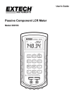
3.1 Descripción de los mandos y elementos.
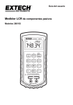
Figura 1.- MZ-505C, panel frontal.
1.
Pantalla LCD.
2.
04/2015
Botón de alimentación ON/OFF.
Página 9
Manual de instrucciones. MZ-505C
3.
Botón de escala.
4.
Botón de modo de suspensión de datos y encendido
de retroiluminación.
5.
Botón de selección de modo relativo.
6.
Botón selección frecuencia de test.
7.
Botón selección Paralelo o en Serie.
8.
Botón selección función Resistencia, Capacidad e
Inductancia.
9.
Botón selección Q/D/R.
10.
Botón de selección lectura-memorización Máximo,
Mínimo y Promedio.
11.
Botón de ajuste.
12.
Botón de ajuste límites superior e inferior.
Botón selección de Tolerancia.
13.
14.
Terminales y zócalos de entrada.
15.
Salida RS-232 optoacoplada.
16.
Conector de entrada 12V DC. Alimentación exterior.
Página 10
04/2015
Manual de instrucciones. MZ-505C
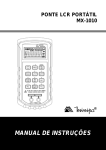
3.2 Mensajes de la Pantalla LCD.
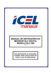
Figura 2.- Pantalla LCD.
1.
APO:
Indicador de Autoapagado Activado.
2.
Indicador comunicación RS232 Activada.
3.
Indicador modo registro.
4.
Δ
Indicador de modo relativo.
5.
MAX
Indicador de lectura máxima.
6.
TOL
Indicador de modo tolerancia.
7.
MIN
Indicador lectura mínima.
8.
AVG
Indicador lectura media.
9.
R
Indicador de resistencia en serie o paralelo.
10. Q
04/2015
Indicador de factor de calidad.
Página 11
Manual de instrucciones. MZ-505C
11. D
Indicador de factor de Disipación.
12. SER
Indicador de modo serie.
13. PAL
Indicador de modo paralelo.
14.
8888
Pantalla secundaria.
15. %
Indicación de tolerancia (porcentaje).
16. KMΩ
Indicador Resistencia (MΩ / kΩ / Ω).
17. 1kHz
Indicador de frecuencia.
18. 120Hz
Indicador de frecuencia.
19.
Indicador de tono acústico para modo de tolerancia.
20. KMΩ
Indicador Resistencia (MΩ / kΩ / Ω).
21. μmH
Indicador Inductancia (μH / mH / H).
22. nμnpF
Indicador Capacitancia (pF / μF / mF / F).
23. AUTO
Indicador de autorrango.
24.
Indicador retención de datos.
25. SET
Indicador de modo Ajuste.
26. LCR:
Indicador de función L=inductancia, C=capacidad o
R=resistencia.
27.
Indicador de limites de alta tolerancia.
28.
Indicador de limites de baja tolerancia.
29.
Página 12
:
Indicador de batería baja.
04/2015
Manual de instrucciones. MZ-505C
3.2.1 Indicadores especiales
shrt
OPEN
CAL
FUSE
Indica cortocircuitar puntas de prueba para el modo
calibración.
Indica dejar puntas de prueba abiertas para el modo
calibración.
Indica modo calibración.
Indica fusible dañado o fundido.
3.3 Cómo operar
PRECAUCIÓN
Nota:
Para obtener una precisión óptima en todas las medidas de
L, C y R así como en los extremos de las escalas, se
recomienda calibrar el medidor antes de realizar las
comprobaciones.
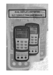
3.3.1 Medición de inductancia
1.
Pulse la tecla
instrumento.
2.
[8] y seleccione la medición de
Pulse la tecla
inductancia (L).
Inserte una inductancia en el zócalo de componentes o
conéctela a las puntas de prueba, según convenga.
3.
04/2015
[2] para poner en marcha el
Página 13
Manual de instrucciones. MZ-505C
[6] para seleccionar la frecuencia de
4.
Pulsar el botón
prueba.
5.
Pulsar el botón
[9] para seleccionar el factor Q en la
pantalla secundaria.
Lea los valores de la inductancia y del factor de calidad.
6.
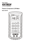
Figura 3.- Medición de inductancia.
3.3.2 Medición de capacidad
1.
Pulse la tecla
instrumento.
2.
Pulse la tecla
capacidad (C).
Página 14
[2] para poner en marcha el
[8] para seleccionar la medición de
04/2015
Manual de instrucciones. MZ-505C
3.
Inserte el condensador en el zócalo de componentes o
conéctelo a las puntas de prueba, según convenga.
4.
Pulsar el botón
prueba.
[6] para seleccionar la frecuencia de
5.
Pulsar el botón
pantalla secundaria.
[9] para seleccionar el factor D en la
6.
Lea los valores de la capacidad y del factor de disipación.
Peligro
Para evitar riesgos descargue el condensador antes de medirlo.
Figura 4.- Medición de capacidad.
04/2015
Página 15
Manual de instrucciones. MZ-505C
3.3.3 Medición de resistencia
1.
Pulse la tecla
instrumento.
[2] para poner en marcha el
2.
Pulse la tecla
resistencia (R).
[8] y seleccione la medición de
3.
Inserte una resistencia en el zócalo o conéctela a las puntas
de prueba, según convenga.
4.
Pulsar el botón
prueba.
5.
Lea el valor de la resistencia.
[6] para seleccionar la frecuencia de
Figura 5.- Medición de resistencia
Página 16
04/2015
Manual de instrucciones. MZ-505C
4 INSTRUCCIONES DE OPERACIÓN
4.1 Apagado Automático
Si no se utiliza durante unos 10 minutos, el medidor se apaga
automáticamente. Pulse la tecla
[2] para reencenderlo.
Cuando el medidor esté apagado, pulse la tecla
[2] para
encenderlo. El aparato recuperará la misma configuración que tenía
antes de apagarlo.
La
función
de
apagado
automático
se
desactiva
automáticamente en el modo de grabación MIN MAX, en el modo
comunicación RS-232 o cuando se utiliza el adaptador de corriente
DC.
4.1.1 Medición Continua
[2] durante
Con el instrumento apagado, presione la tecla
dos segundos, hasta que aparezca el mensaje APO OFF en
pantalla. El medidor se pondrá en modo de medición continua y el
apagado automático quedará desactivado.
4.1.2 Interruptor de Encendido.
La tecla
[2] enciende y apaga el medidor. Si el
instrumento tiene un error de estado, pulse la tecla
que se apague.
04/2015
[2] hasta
Página 17
Manual de instrucciones. MZ-505C
4.2 Selección de FRECUENCIA
[6], entre
Seleccione la frecuencia mediante la tecla
120 Hz o 1 kHz, en función del elemento a comprobar. Un
condensador electrolítico se configura a 120 Hz para los demás
generalmente se configura a 1 kHz.
4.3 Modo SERIE / PARALELO
Mediante el botón
[7] cambie entre modo de medición en
paralelo o en serie. Si el elemento tiene una alta impedancia, en
general la medición se realiza en modo “circuito paralelo
equivalente” "PAL", mientras que si el elemento tiene una
impedancia baja, la medición se realiza en modo “circuito serie
equivalente” "SER".
Nota:
Para las resistencias (R) solo está disponible el modo paralelo
(PAL).
4.4 Botón ESCALA (RANGE)
Pulse la tecla
[4] para pasar al modo de Escala Manual y
desactivar el modo Auto, cuyo indicativo desaparece de la pantalla.
(El medidor se mantiene en la escala en la que se encontraba
cuando se seleccionó el modo de Rango Manual).
En el modo de Rango Manual cada vez que se pulse la tecla
[4], la escala (y el indicativo de ésta en pantalla) se
incrementa, y se muestra un nuevo valor. Para salir del modo de
Escala Manual y regresar a la selección automática de escala,
mantenga pulsada la tecla
[4] durante 2 segundos. El
indicativo “AUTO” volverá a aparecer en pantalla.
Página 18
04/2015
Manual de instrucciones. MZ-505C
4.5 Tecla de función L/C/R (Sólo en indicador principal)
La tecla
[8] cambia los parámetros de medida en la
secuencia L-C-R-L ..., el indicativo correspondiente aparece en la
pantalla LCD.
Cuando se enciende el medidor, se establecen los parámetros
de medida que habían cuando el medidor se apagó por última vez.
4.6 Tecla de función
secundario)
Q/D/R
(Sólo
en
indicador
[9]cambia los parámetros de medida en la
La tecla
secuencia Q-D-R-Q ..., el indicativo correspondiente aparece en la
pantalla LCD.
Cuando se enciende el medidor, se establecen los parámetros
de medida que habían cuando el medidor se apagó por última vez.
4.7 HOLD >2 SEGUNDOS
Pulse la tecla
[4] para entrar en el modo de suspensión de
datos y aparecerá la letra "H" en la pantalla.
Cuando se selecciona el modo suspensión, el medidor detiene
el resto de mediciones. Si pulsa la tecla
[4] durante
2 segundos se enciende la retroiluminación. Pulsando de nuevo
esta tecla durante 2 segundos se apaga la retroiluminación.
04/2015
Página 19
Manual de instrucciones. MZ-505C
La retroiluminación se apaga automáticamente después de 1
minuto.
4.8 BOTONES MIN / MAX
Pulse la tecla
[10] para entrar en el modo MIN / MAX /
AVG y detener la función de Auto-Apagado. En este modo, todas
las teclas quedan bloqueadas a excepción de la tecla de encendido
[4]. Cuando el medidor toma aproximadamente 6
y la tecla
medidas, emitirá un bip. A partir de aquí, cuando registre un nuevo
máximo o mínimo de datos, emitirá dos sonidos.
El valor de la pantalla principal (y el valor de segunda pantalla)
[10] desde el valor actual (valor
se cambia pulsando la tecla
de parámetro) → valor máximo (valor de parámetro) → valor mínimo
(valor de parámetro) → valor máximo menos el valor mínimo
(número de comprobaciones) → El valor promedio en pantalla
(número de comprobaciones).
El medidor ignorará y no registrará los datos en caso que ocurra
una situación de sobrecarga ("OL") en los procesos comparativos o
en la escala de capacitancia es menor o igual a 50 cuentas.
El valor medio de las medidas que aparece en pantalla es el
registro de una media real. El instrumento almacena hasta 3000
medidas. El indicador "AVG" de la pantalla parpadeará cuando se
alcance un número entre 2991 y 3000 medidas. Al superar las 3000
medidas el “AVG” dejará de registrar y mostrará el valor medio en
pantalla. El medidor seguirá registrando los valores Max / Min.
Página 20
04/2015
Manual de instrucciones. MZ-505C
Mientras trabaje con la función Max/Min, pulse la tecla
[4].
para detener la grabación temporalmente, pero guarde los datos del
registro anterior. Pulse
grabación.
[4], de nuevo para continuar con la
Con el fin de evitar errores o pérdidas de datos, pulse durante
2 segundos para salir de la Max/Min y cancelar la grabación
original.
4.9 AJUSTES
1. La tecla
[11] está activada solamente después de
encender el instrumento y antes de pulsar cualquier otra
tecla.
2.
Pulse la tecla
[11] para entrar en el modo de ajuste y
cambiar al modo Escala Manual automáticamente.
3.
Al entrar en la función SET, la pantalla principal queda
despejada, mientras que la segunda pantalla muestra el
, .
indicativo "SET". Parpadeando aparece Δ, TOL,
Hay sólo cinco teclas que se pueden utilizar: la de
encendido,
04/2015
[11],
[5],
[12] y
[13].
Página 21
Manual de instrucciones. MZ-505C
4. Calibración SHORT, OPEN:
Pulse la tecla
[11] y la pantalla mostrará el mensaje
CAL OPEN.
A continuación pulse la tecla
[7]
(ENTER). El programa entra en el modo rápido de
calibración. Si no quiere proceder a realizar la calibración
rápida pulse
[11] para salir. Cuando la pantalla
muestre CAL SHRT, pulse la tecla
[7] (ENTER). El
programa entra en modo de calibración rápida. Al terminar
el instrumento vuelve al modo de trabajo normal.
5. Ajustes de Límites superior e inferior (Hi/Lo)
[12] y la pantalla LCD muestra en
Pulse la tecla
pantalla el símbolo ^ parpadeando. También aparece el
valor superior configurado previamente y permitirá al usuario
realizar modificaciones sobre este. Cuando se introduzca el
valor de ajuste inferior, el indicativo de la punta de flecha
hacia abajo parpadeará. El anterior ajuste inferior también
aparecerá y permitirá al usuario realizar los cambios.
Si el valor inferior (Lo) es mayor que el valor superior (Hi),
aparece en pantalla el mensaje Err y vuelve al modo de
ajuste del valor superior (Hi), para introducir de nuevos los
valores superior e inferior (Hi/Lo).
Página 22
04/2015
Manual de instrucciones. MZ-505C
6. Ajuste de los límites de tolerancia superior e inferior:
[13], la pantalla LCD mostrará TOL
Pulse
parpadeando. La configuración anterior al valor estándar
también aparecerá y permitirá al usuario hacer las
modificaciones. Cuando se introduce el valor de ajuste
+ TOL, el indicativo "TOL" " " parpadearán. El ajuste
previo + TOL también aparecerá y permitirá al usuario hacer
modificaciones. Si se introduce el valor de ajuste - TOL, los
indicativos "TOL” “ " parpadearán. La configuración
anterior - TOL también aparecerá y permitirá al usuario
hacer modificaciones.
7. Ajuste REL
Pulse la tecla "REL". La pantalla LCD mostrará la D
parpadeando. El ajuste previo también aparecerá y permitirá
al usuario hacer modificaciones.
8. Configuración de Datos:
Cuando se quiera introducir datos usando los caracteres
situados encima de cada tecla y serigrafiados sobre la
carcasa, aparecerá el dato existente previo y el lugar en
espera de ser editado parpadeará. La introducción de datos
empieza por el número de mayor rango. El número más
grande que se puede introducir en esta posición es el 1.
Que se puede introducir es el 1, aparecerá este número
parpadeando. En caso que sea 0, aparecerá el segmento
inferior parpadeando. Pulse “1” si el valor a introducir es
uno, o pulse cualquier otra tecla si el valor a introducir es
cero. Pulse “ENTER” si quiere salir sin realizar ningún
cambio. La función “TOL” y “HI/LO Limits” no tienen
limitación por número más grande.
04/2015
Página 23
Manual de instrucciones. MZ-505C
Después de introducir los 5 dígitos no habrá ningún
número parpadeando. En ese momento se podrá variar
entre el símbolo “+/-“ pulsando la tecla “0”.
Precaución: Si al pulsar la tecla "ENTER", se emiten dos bips
seguidos, los datos se almacenarán en el
almacenamiento volátil. Los datos se almacenan en la
región de almacenamiento no volátil cuando el
medidor se apague. En este modo el apagado
automático está desactivado.
4.10 REL Modo Relativo (sólo en la pantalla principal)
Pulse la tecla "REL" para entrar el modo relativo. La lectura en
pantalla se almacena como un valor de referencia, la pantalla se
pone a cero y se muestra el símbolo "Δ". Pulse de nuevo la tecla
REL para salir del modo relativo.
Por ejemplo: Si la lectura indicada es 100,0, presione REL para
almacenarlo como valor de referencia, y seguidamente la pantalla
se pondrá a cero. Si almacenamos 100,0 como valor de referencia
estándar y nuestra señal de entrada es 99,5, la lectura será
99,5-100,0 que es igual a -0,5.
El usuario (consulte el apartado "SET" de este manual) también
establecer el valor relativo. Cuando se ha introducido el valor
relativo deseado, pulse la tecla
[5] para entrar en el modo
Relativo, y a continuación pulse la tecla
como valor de referencia. Pulse
modo relativo.
Página 24
[11] el valor relativo
[5] de nuevo para salir del
04/2015
Manual de instrucciones. MZ-505C
4.11 LÍMITES HI / LO (Superior / Inferior)
[12] para entrar en el modo “LIMITES
Pulse la tecla
Hi / Lo” y cámbielo al modo de escala manual. El valor inicial de
“LIMITES Hi/Lo” y los indicadores “ ” “ “ aparecerán en pantalla
al mismo tiempo de forma individual.
Cuando la entrada excede el límite superior, la señal " "
parpadea y emite un tono continuo. Cuando la entrada está por
debajo del límite inferior “Lo”, el “ ” parpadea y emite un tono
discontinuo. Esto advierte a los usuarios que se encuentra fuera de
los límites de margen. Debe presionar "Hi/Lo LÍMITES" de nuevo
para salir de este modo.
Además, el medidor ignorará y no registrará en situación de
sobrecarga (“OL”) en los procesos comparativos o cuando el rango
de capacitancia sea inferior o igual a 50 unidades
4.12 TOL
Presione
[13] para entrar en el modo tolerancia, y cambia
al modo de escala manual automáticamente. El valor original
preestablecido estándar y el indicador “TOL” aparecerán al mismo
tiempo. Para configurar un valor estándar consulte el apartado SET
del manual. Al entrar en el modo TOL, la pantalla principal muestra
el valor actual y la segunda pantalla el valor de la tolerancia.
04/2015
Página 25
Manual de instrucciones. MZ-505C
Hay 4 valores pre-configurados en el modo TOL para uso
[13] sucesivamente para
inmediato. Solamente debe pulsar
pasar por los valores 1%, 5%, 10%, 20% y vuelve de nuevo al valor
inicial. Al entrar en el modo TOL, los indicadores " " y " "
aparecen a la vez. Cuando la entrada excede el límite superior, la
señal " " parpadea y emite un tono continuo. Cuando la entrada
está por debajo del límite inferior “Lo”, el “ ” parpadea y emite un
tono discontinuo. Esto advierte a los usuarios que se encuentra
fuera de los límites de margen.
El valor estándar se puede configurar a través de la función
SET. Si tiene dudas al respecto consulte al apartado de
configuración SET de este manual. Cuando el valor estándar esté
configurado, debe presionar la tecla
[13] y a continuación
[11] para utilizar la configuración TOL pre-establecida.
Además, el medidor ignorará y no registrará en situación de
sobrecarga (“OL“) en los procesos comparativos o cuando el rango
de capacitancia sea inferior o igual a 50 unidades. Presione la tecla
[13] dos segundos para salir de esta función.
4.13 Detección automática del estado del fusible
Cuando el medidor detecta que el fusible está fundido,
aparecerá el mensaje "FUSE" y sonará un tono continuo. En tal
caso, no actuará ninguna de las teclas de función y todas las demás
funciones del medidor se desactivarán. Será necesaria la sustitución
del fusible.
Página 26
04/2015
Manual de instrucciones. MZ-505C
Figura 6.- Detección del estado del fusible.
4.14
Calibración
El proceso de calibración se activa de manera automática en
ciertos tipos de medida y según sea la escala, aunque también se
puede realizar de manera manual en cualquier escala. Simplemente
[11] dos veces y aparecerán las señales de
pulse la tecla
calibración en la pantalla. Si aparece en pantalla la indicación
(OPEN) mantenga los terminales de las puntas de prueba abiertos.
Si aparece la indicación (SHRT) cortocircuite los terminales de las
[11] Una vez
puntas de prueba. y pulse nuevamente la tecla
realizado el paso correspondiente la pantalla del instrumento
volverá a su imagen habitual y estará listo para su uso.
Figura 7.- Calibración circuito abierto / cortocircuito
04/2015
Página 27
Manual de instrucciones. MZ-505C
La función calibra los parámetros internos del medidor así como
los residuales correspondientes al conector y cables de medida para
posteriores medidas. Es altamente recomendable para las escalas
más altas y las más bajas de L/C/R antes de efectuar mediciones
que requieran precisión. Los signos de calibración aparecerán en la
pantalla LCD de forma automática cada vez que seleccione sus
escalas manualmente o a través de una función, (ej. REL, TOL,
REC etc.), y siempre que sea aconsejable.
Simplemente siga la indicación de circuito abierto (OPEN) o de
cortocircuito (SHRT) y luego pulse la tecla
la calibración pulsando la tecla
Notas:
[11]. Puede evitar
[9].
1.- Al cambiar de frecuencia de medición se producirá lo
mismo que ocurre cuando selecciona escalas
distintas: aparecerán los signos de calibración en las
escalas adecuadas.
2.- Asegúrese que utiliza la misma posición después de
la calibración en cortocircuito.
4.15 Indicador de pila descargada
Cuando aparezca el símbolo “
” en la pantalla, la tensión de
la pila se encuentra por debajo de la tensión de trabajo y se está
debilitando. Sustitúyala por una nueva para mantener la precisión
del instrumento.
Página 28
04/2015
Manual de instrucciones. MZ-505C
5 MANTENIMIENTO
PELIGRO
Para evitar el choque eléctrico, no realice ninguna labor de
mantenimiento excepto si está cualificado para ello.
5.1 Mantenimiento
Si el instrumento falla durante su operación, verifique la pila y
las puntas de prueba, y sustitúyalas en caso necesario. Si el
instrumento continua sin funcionar, compruebe que sigue el
procedimiento para su operación descrito en este manual. Para el
mantenimiento utilice únicamente los recambios especificados. El
medidor debe ser desconectado de cualquier fuente de alimentación
mientras se sustituye el fusible o la batería.
5.2 Sustitución de la pila
El medidor es alimentado por una única pila de 9V, tipo
IEC6F22 carbón-zinc o alcalina. Sustituir la pila cuando el símbolo
) aparezca parpadeando en la pantalla. Siga el
de batería baja (
siguiente procedimiento para sustituir la pila:
1. Extraiga los tornillos y retire la tapa inferior como se muestra
en la figura 10.
04/2015
Página 29
Manual de instrucciones. MZ-505C
2. Sustituya la pila agotada por una nueva respetando la
polaridad indicada.
Figura 8.- Sustitución de la pila.
5.3 Sustitución del fusible
El medidor detecta automáticamente si el fusible de protección
de la entrada se encuentra fundido o dañado. En tal caso, en la
pantalla LCD se visualizará el símbolo "FUSE" y un tono audible
(Bip) sonará de forma continua, avisando al usuario de la necesidad
de sustituir el fusible dañado para volver a tener operativo el
medidor. Durante la sustitución del fusible, debe retirarse cualquier
alimentación del medidor.
1.
Aflojar los tornillos con un destornillador adecuado y
retirar la tapa del compartimiento de la pila como se
indica en la figura 9.
2.
Aflojar los tornillos con un destornillador adecuado y
retirar la tapa inferior del compartimiento de la pila como
se indica en la figura 9.
Página 30
04/2015
Manual de instrucciones. MZ-505C
3.
Sustituir el fusible
especificado.
dañado
por
otro
según
lo
EL FUSIBLE DEBE SER DEL TIPO: 5 x 20 mm., y:
0,1 A
F
250 V
EL INCUMPLIMIENTO DE ESTAS INSTRUCCIONES
PODRÍA DAÑAR EL EQUIPO
Figura 9.- Sustitución del fusible.
04/2015
Página 31
Manual de instrucciones. MZ-505C
5.4 Recomendaciones de limpieza
PRECAUCIÓN
Para limpiar la caja, asegurarse de que el equipo está desconectado.
PRECAUCIÓN
No se use para la limpieza hidrocarburos aromáticos o disolventes
clorados. Estos pueden atacar a los materiales utilizados en la
construcción de la caja.
La caja se limpia con una ligera solución de detergente con agua y
aplicada mediante un paño suave humedecido.
Secar completamente antes de volver a usar el equipo.
Página 32
04/2015
INSTRUCTION MANUAL. MZ-505C
TABLE OF CONTENTS
1 GENERAL .....................................................................................1
1.1 Introduction .........................................................................1
1.2 Specifications ......................................................................2
2 SAFETY RULES ...........................................................................7
3 OPERATING INSTRUCTIONS .....................................................9
3.1 Description of the controls and elements. ...........................9
3.2 LCD Display illustration .....................................................11
3.3 How to operate..................................................................13
3.3.1 Inductance measurement ............................................13
3.3.2 Capacitance measurement .........................................14
3.3.3 Resistance measurement............................................15
4 OPERATING INSTRUCTIONS ...................................................17
4.1 Autopower down ...............................................................17
4.1.1 Continuous Mesurement .............................................17
4.1.2 Power Switch...............................................................17
4.2 Frequency select...............................................................18
4.3 Parallel/Series mode .........................................................18
4.4 RANGE Button ..................................................................18
4.5 L/C/R Function button (only main indicator)......................19
4.6 Q/ D/ R FUNCTION BUTTON (secondary display)...........19
4.7 HOLD. > 2sec. ..................................................................19
4.8 MIN/ MAX BUTTON ..........................................................20
4.9 SET ...................................................................................21
4.10 REL. Relative mode (only Main display) ...........................23
4.11 HI/LO LIMITS ....................................................................24
4.12 TOL ...................................................................................24
4.13 Automatic fuse status detection ........................................25
4.14 Calibration .........................................................................26
4.15 Low battery indication .......................................................27
User’s manual. MZ-505C
5 MAINTENANCE ..........................................................................29
5.1 Service ..............................................................................29
5.2 Battery replacement ..........................................................29
5.3 Fuse replacement .............................................................30
5.4 Cleaning recommendations ..............................................31
INSTRUCTION MANUAL. MZ-505C
DUAL DISPLAY L/C/R METER
MZ-505C
1 GENERAL
1.1 Introduction
This 19.999 count L/C/R hand-held meter is a special
microprocessor-controlled meter for measuring functions of
inductance, capacitance and resistance. Simple to operate, the
instrument not only takes absolute parallel mode measurements, but
also capable of series mode measurement. The meter provides
direct and accurate measurements of inductors, capacitors and
resistors with different testing frequencies. It is selectable for auto
and manual ranging.
Front panel pushbuttons maximize the convenience of function
and feature selection such as data hold; maximum, minimum and
average record mode; relative mode; tolerance sorting mode;
frequency and L/C/R selection.
The test data can be transferred to PC through an full isolated
optical RS232C interface.
A tilt stand provides position flexibility for viewing and operating
the meter. The over-melding plastic and rubber case protects the
meter to be stronger. With single 9V battery operation is standard for
the meter, a DC 12V power adaptor can also be used as an optional
power input.
04/2015
Page 1
INSTRUCTION MANUAL. MZ-505C
1.2 Specifications
Parameters measured
Displays
L/C/R
Q/D/R
Measuring ranges
C (120 Hz)
C (1 kHz)
L (120 Hz)
L (1 kHz)
R
Resolution
R
L
C
Ranging mode
Measuring terminals
Test frequency
Tolerance mode
Measuring rate
Response time
Auto power-off
Temperature coefficient
Page 2
LS + (Q, D, RS), LP + (Q, D, RP), CS
+ (Q, D, RS), CP + (Q, D, RP).
Maximum Display 4 ½ digit 19999
counts.
Display 4 digit 999.9 count
maximum (Autoranging).
1 pF ~ 10 mF (basic
0.7 %).
0.1 pF ~ 1000 μF (basic
0.7 %).
1 μH ~ 10000 H (basic
0.7 %).
0.1 μH ~ 1000 H (basic
0.7 %).
1 mΩ ~ 10 MHΩ (basic
0.5 %).
accuracy
accuracy
accuracy
accuracy
accuracy
Up 0.001 Ω.
Up 0.1 μH.
Up 0.1 pF.
Auto & Manual.
2 terminals with sockets.
1 KHz, 120 Hz.
1 %, 5 %, 10 %, 20 %.
1 measurement x seconds, nominal.
Approx. 1 second at manual range.
10
minutes
approx.
without
operation.
0,15 x (specific accuracy)/°C
(0-18 °C and 28-40 °C).
04/2015
INSTRUCTION MANUAL. MZ-505C
Low battery indicator
Voltage measurement
Input protection
POWER SUPPLY
Internal
External
Consumption
The symbol
screen.
600 mV AC.
Fuse.
- +
appears on the
Battery 9 V IEC6F22.
12 to 15 V DC.
Aprox. 12 mA for operation
0.03 mA After auto power-off
Operating environmental conditions
Altitude
Up to 2000 m
Temperature range
From 0 °C to 40 °C
Max. relative humidity
80 % (up to 31 °C), decreasing
lineally up to 50% at 40 °C
Mechanical properties
Dimensions
Weight
L. 91 x W. 192 x H. 52,5 (mm).
Aprox.
365
gr.
(Accessories
Included).
Standard accessories
Test alligator clips (pair).
Kit for RS-232 + software.
DC 9V battery (IEC 6F22 ).
Instruction Manual.
Optional accessories
SMD Tweezers PP-009.
04/2015
Page 3
INSTRUCTION MANUAL. MZ-505C
Ranges and accuracies
Accuracy ± (% of reading ± num. of digits) at 23°C ±5°C, RH<75%.
Resistance
Test Frequency: 120 Hz / 1 KHz
Range
Maximum
Display
10 MΩ
2MΩ
200kΩ
20kΩ
2kΩ
200Ω
20Ω
10 MΩ
1.9999MΩ
199.99kΩ
19.999kΩ
1.9999kΩ
199.99Ω
19.999Ω
Accuracy
at 120 Hz
at 1 KHz
±(2.0%+8 dig)
± (0.5%+5 dig)
± (0.5%+3 dig)
± (0.5%+3 dig)
± (0.5%+3 dig)
± (0.8%+5 dig)
± (1.2%+4 dig)
Specified Note
± (2.0%+8 dig)
± (0.5%+5 dig)
± (0.5%+3 dig)
± (0.5%+3 dig)
± (0.5%+3 dig)
± (0.8%+5 dig)
± (1.2%+4 dig)
After open cal.
After open cal.
After short cal.
After short cal.
Capacitance
Test Frequency: 120 Hz
Range
Maximum
Display
20mF
10mF
2000μF
1999.9μF
200μF
199.99μF
20μF
19.999μF
2000nF
1999.9nF
200nF
199.99nF
20nF
19.999nF
Page 4
Accuracy
Capacity.
DF
± (5.0%+5 dig)
DF<0.1
± (1.0%+5 dig)
DF<0.1
± (0.7%+3 dig)
DF<0.5
± (0.7%+3 dig)
DF<0.5
± (0.7%+3 dig)
DF<0.5
± (0.7%+5 dig)
DF<0.5
± (1.0%+5 dig)
DF<0.1
± (10%+100/Cx+5 dig)
(DF<0.1)
± (2%+100/Cx+5 dig)
(DF<0.1)
± (0.7%+100/Cx+5 dig)
(DF<0.5)
± (0.7%+100/Cx+5 dig)
DF<0.5
± (0.7%+100/Cx+5 dig)
DF<0.5
± (0.7%+100/Cx+5 dig)
DF<0.5
± (2%+100/Cx+5 dig)
DF<0.1
Specified
Note
After short
cal.
After short
cal.
After open
cal.
After open
cal.
04/2015
INSTRUCTION MANUAL. MZ-505C
Test Frequency: 1 KHz
Range
Maximum
Display
2000μF
1000.0μF(2)
200μF
199.99μF(3)
20μF
19.999μF
2000nF
1999.9nF
200nF
199.99nF
20nF
19.999nF
2000pF
1999.9pF
Accuracy
Capacity.
DF
± (5.0%+5 dig)
± (10%+100/Cx+5 dig)
DF<0.1
± (1.0%+5 dig)
DF<0.1
± (0.7%+3 dig)
DF<0.5
± (0.7%+3 dig)
DF<0.5
± (0.7%+3 dig)
DF<0.5
± (0.7%+5 dig)
DF<0.5
± (1.0%+5 dig)
DF<0.1
DF<0.1
± (2.0%+100/Cx+5 dig)
DF<0.1
± (0.7%+100/Cx+5 dig)
DF<0.5
± (0.7%+100/Cx+5 dig)
DF<0.5
± (0.7%+100/Cx+5 dig)
DF<0.5
± (0.7%+100/Cx+5 dig)
DF<0.5
± (2.0%+100/Cx+5 dig)
DF<0.1
Specified
Note
After short
cal.
After short
cal.
After open
cal.
After open
cal.
Notes: Q Value is the reciprocal of DF (dissipation factor).
This specification is based on the measurement performed
at the test socket.
Inductance
Test Frequency: 120 Hz
Range
Maximum
Display
20000H
10000H
1000H
999.9H
200H
199.99H
20H
19.999H
2000m
1999.9mH
200m
199.99mH
20m
19.999mH
04/2015
Accuracy
Inductance
DF
unspecified
unspecified
± (1.0%+ Lx/10000% +5 dig)
DF<0.5
± (0.7%+ Lx/10000%+5 dig)
DF<0.5
± (0.7%+ Lx/10000%+5 dig)
DF<0.5
± (0.7%+ (Lx/10000)%+5
dig) DF<0.5
± (1.0%+ Lx/10000%+5 dig)
DF<0.5
± (2.0%+ Lx/10000%+5 dig)
DF<0.5
(2%+100/Lx+5 dig)
DF<0.5
(1.2%+100/Lx+5 dig)
DF<0.5
(1.2%+100/Lx+5 dig)
DF<0.5
(1.2%+100/Lx+5 dig)
DF<0.5
(3%+100/Lx+5 dig)
DF<0.5
(10%+100/Lx+5 dig)
DF<0.5
Specifie
d Note
After
open cal.
After
short cal.
After
short cal.
Page 5
INSTRUCTION MANUAL. MZ-505C
Test Frequency: 1 KHz
Accuracy
Range
Maximu
m
Display
2000H
1000.0
unspecified
unspecified
200H
199.99H
± (1.0%+ Lx/10000%+5 dig)
DF<0.5
± (2.0%+100/Lx+5 dig)
DF<0.5
20H
19.999H
2000mH
1999.9mH
200mH
199.99mH
± (0.7%+ Lx/10000%+5 dig)
DF<0.5
± (0.7%+ Lx/10000%+5 dig)
DF<0.5
± (0.7%+ Lx/10000%+5 dig)
DF<0.5
± (1.2%+100/Lx+5 dig)
DF<0.5
± (1.2%+100/Lx+5 dig)
DF<0.5
± (1.2%+100/Lx+5 dig)
DF<0.5
Inductance
DF
20mH
19.999mH
± (1.0%+ Lx/10000%+5 dig)
DF<0.5
± (3.0%+100/Lx+5 dig)
DF<0.5
2000μH
1999.9μH
± (2.0%+ Lx/10000%+5 dig)
DF<0.5
± (10%+100/Lx+5 dig)
DF<0.5
Specifie
d Note
After
open
cal.
After
short
cal.
After
short
cal.
Notes: Q Value is the reciprocal of DF.
This specification is based on the measurement performed
at the test socket.
Page 6
04/2015
INSTRUCTION MANUAL. MZ-505C
2 SAFETY RULES
*
*
*
*
The safety could not be assured if the instructions for use
are not closely followed.
When measuring components in circuit you must previously
disconnect the power supply.
When measuring capacitors is necessary to discharge them
previously.
When using some of the following accessories use only the
specified ones to ensure safety:
Battery 9V 6F22.
*
*
*
*
Observer all
measurement.
specified
ratings
both
of
supply
and
Use this instrument under the specified environmental
conditions.
Remember that voltages higher than 70 V DC or 33 V AC rms
are dangerous.
The user is only authorised to carry out the following
maintenance operations:
Replace the battery.
Fuse replacement
On the Maintenance paragraph the proper instructions are given.
Any other change on the equipment should be carried out by
qualified personnel.
04/2015
Page 7
INSTRUCTION MANUAL. MZ-505C
*
*
Follow the cleaning instructions described in the Maintenance
paragraph.
Symbols related with safety:
Page 8
04/2015
INSTRUCTION MANUAL. MZ-505C
3 OPERATING INSTRUCTIONS
3.1 Description of the controls and elements.
Figure 1.- MZ-505C, front panel.
1. LCD display.
2.
04/2015
Power ON/OFF button.
Page 9
INSTRUCTION MANUAL. MZ-505C
3.
Scale button.
4.
Standby button and data on the backlight.
5.
Mode Selection button on.
6.
Test button frequency selection.
7.
Button Parallel or Serial selection.
8.
Resistance function selection button, Capacity and
Inductance.
9.
Selection button Q/D/R.
10.
Read-button preset selection Max, Min and Average.
11.
Adjustment Button.
12.
Adjustment knob upper and lower limits.
13.
Tolerance selection button.
14. Input terminals and sockets.
15. RS-232 Output optocoupler.
16. 12V DC input connector. External power supply.
17. Optic interface.
Page 10
04/2015
INSTRUCTION MANUAL. MZ-505C
3.2 LCD Display illustration
Figure 2.- LCD Display.
1.
APO
On AutoShutdown indicator.
2.
RS232 indicator.
3.
Record mode indicator.
Δ
Mode indicator on.
5.
MAX
Maximum reading indicator.
6.
TOL
Tolerance mode indicator.
7.
MIN
Minimum reading indicator.
8.
AVG
Average reading indicator.
9.
R
Indicator of resistance in series or parallel.
4.
04/2015
Page 11
INSTRUCTION MANUAL. MZ-505C
10. Q
Quality factor indicator.
11. D
Dissipation factor indicator.
12. SER
Series mode indicator.
13. PAL
Parallel mode indicator.
14.
8888
Secondary display.
15. %
Tolerance (percentage) indicator.
16. KMΩ
Resistance (MΩ / kΩ / Ω) indicator.
17. 1kHz
Frequency indicator.
18. 120Hz
Frequency indicator.
19.
Beeper tone indicator for tolerance mode.
20. KMΩ
Resistance (MΩ / kΩ / Ω) indicator.
21. μmH
Inductance (μH / mH, H) indicator.
22. nμnpF
Capacitance (pF / μF / mF / F) indicator.
23. AUTO
Auto-ranging indicator.
24.
Indicator data retention.
25. SET
Mode Indicator Set.
26. LCR
L=inductance,
C=capacitance
function indicator.
27.
Indicator of high tolerance limits.
28.
Indicator of low tolerance limits.
29.
Page 12
:
or
R=resistance
Low battery indicator.
04/2015
INSTRUCTION MANUAL. MZ-505C
Special indication characters
shrt
OPEN
CAL
FUSE
Indicates short connectors for calibration mode
Indicates open connectors for calibration mode
Indicates calibration mode.
Indicates damaged or open fuse.
3.3 How to operate
CAUTION
Note:
For achieving optimum precision for all L, C and R
measurements at either the highest or lowest ranges, it is
recommended to calibrate the meter before testing.
3.3.1 Inductance measurement
1.
Press the
2.
[8] button to select inductance (L)
Press
measurement.
Insert an inductor into component receptacle socket or
connect the test clip to the component leads as required.
3.
4.
Press
5.
Press
display.
04/2015
[2] button to turn on the meter.
[6] button to select testing frequency.
[9] button to select Q factor for secondary
Page 13
INSTRUCTION MANUAL. MZ-505C
6.
Read the display readings for inductance value and quality
factor.
Figure 3.- Inductance measurement
3.3.2 Capacitance measurement
1. Press
[2] button to turn on the meter.
[8]
2. Press
measurement.
button
to
select
capacitance
(C)
3. Insert a capacitor into the component receptacle socket or
connect the test clip to the component leads as required.
4. Press
5. Press
display.
Page 14
[6] button to select testing frequency.
[9] button to select D factor for secondary
04/2015
INSTRUCTION MANUAL. MZ-505C
6. Read the display readings for capacitance value and
dissipation factor.
Warning
To avoid electrical hazards, discharge the capacitor to be tested
before measuring.
Figure 4.- Capacitance measurement
3.3.3 Resistance measurement
[2] button to turn on the meter.
1.
Press
2.
Press
[8]
measurement.
04/2015
button
to
select
Resistance
(R)
Page 15
INSTRUCTION MANUAL. MZ-505C
3.
Insert a resistor into the component receptacle socket or
connect the test clip to the component leads as required.
4.
Press
5.
Read the display readings for resistance value.
[6] button to select testing frequency.
Figure 5.- Resistance measurement.
Page 16
04/2015
INSTRUCTION MANUAL. MZ-505C
4 OPERATING INSTRUCTIONS
4.1 Autopower down
If unused for about 10 minutes, the meter will power down
automatically. Press
mode.
[2] button switches to resume power-on
[2] button to turn on the
When the power is down, press
meter. The operating condition return to what they were before the
power was last turned off.
In the MIN MAX record mode, RS-232 communication mode or
using DC power-adaptor auto-power down function is disabled
automatically.
4.1.1 Continuous Mesurement
[2] button 2 seconds. Until
In the power down mode, Push
the APO OFF annunciator appears. Will put the meter into the
continuous measurement mode.
4.1.2 Power Switch
The
[2] button turns the meter on or off. In the
microcomputer failure status press
off.
04/2015
[2] button until the meter
Page 17
INSTRUCTION MANUAL. MZ-505C
4.2 Frequency select
Set the
[6] button switch to 120 Hz or 1 kHz according to
the specimen to be test. Generally, the electrolytic capacitor is set to
120 Hz. Others are set to 1 kHz in general.
4.3 Parallel / Series mode
Set the
[7] button switch to parallel or series measuring
circuit mode. However, in the specimen having a high impedance in
general, measurement is made in “parallel equivalent circuit” mode
“PAL”, while in the specimen having a low impedance,
measurement is made in “series equivalent circuit” mode “SER”.
Note:
For resistances (R) is only available the parallel (PAL) mode.
4.4 RANGE Button
[4] button to select the Manual Range mode and
Press
turn off the “AUTO” enunciator. (The meter remains in the range it
was in when manual ranging was selected).
[4] button,
In the Manual Range mode. Each time press
the range (and the input range enunciator) increments, and a new
value displayed. To exit the Manual Range mode and return to
autoranging, press and hold down
The “AUTO” enunciator turns back on.
Page 18
[4] button for 2 seconds.
04/2015
INSTRUCTION MANUAL. MZ-505C
4.5 L/C/R Function button (only main indicator)
key switch the measurement parameter in sequence
The
Q-D-R-Q..., the enunciator is indicated on LCD.
When the meter is turned on, it is set to the measurement
parameter selected that was in use when the meter was last turned
off.
4.6 Q/ D/ R FUNCTION BUTTON (secondary display)
The
[9] key switch the measurement parameter in
sequence Q-D-R-Q..., the enunciator is indicated on LCD.
When the meter is turned on, it is set to the measurement
parameter selected that was in use when the meter was last turned
off.
4.7 HOLD. > 2sec.
[4] key to enter the data hold mode, the “HOLD”
Press the
enunciator is displayed.
When Hold mode is selected, the meer stops all further
measurements. Press
[4] 2 seconds to start backlit function,
press this key for 2 seconds to exit the Backlit function.
After starting the Backlit for 1 minute, the Backlit function will exit
by itself.
04/2015
Page 19
INSTRUCTION MANUAL. MZ-505C
4.8 MIN/MAX BUTTON
[6] to enter the MIN/MAX/AVG mode, and stop the
Press
auto shut down function. In addition to power and hold key, the other
keys cannot be activated. When the meter samples about 6 times,
and then beeper will emit a sound. When a new Max/Min data being
recorded and then beeper will emit 2 sounds.
Main display value (second display value) cycles through
[6] present value (parameter value) → Max value (parameter value)
→ Min Value (parameter value) → Max value minus Min value
(times to test) → The Average Value's displauy (times to test).
The meter will ignore and not to record if overload (“OL”)
situation happens in the comparative processes or in the
capacitance range 50 counts.
The average value's display is true average recording. It can
save up to 3000 times, the “AVG” annunciator will flash when
recording times reaching 2991 to 3000 times. When recording over
3000 times the “AVG” will stop to record and it will also display the
average value on the LCD. The meter continues to record the
MAX/MIN value.
[4] key to stop
Under the MAX/MIN function, press
recording temporarily but store the former recording value in
advance, pres
[4] again to go on recording.
In order to prevent any mistakes or losses taken, you have to
press 2 sec to exit the Max/ Min function and cancel the original
recordings.
Page 20
04/2015
INSTRUCTION MANUAL. MZ-505C
4.9 SET
1. The
[11] can only be activated only before you have
not used any other functions.
2. Press
[11] to enter the SET mode, and change to
manual range mode automatically.
3. While in the SET function, the main display is cleared, the
second display shows “SET” annunciators, LCD shows, ^,
TOL, ^,^ flashing. There are only 5 keys that you can use
[2],
moment.
[11],
[5],
[12],
[13] in this
4. OPEN, SHORT calibration:
Press
[11], LCD will display
CAL open,
and press
[7] (ENTER), the program enters “OPEN” calibration,
after completing the open. The LCD displays CAL, Shrt,
press
[7]. The program enters Short calibration. If you
do not want to proceed Short Calibration, and press
[7]
[11], to exit. When LCD shows CAL Shrt, press
(ENTER) key. The program enters “SHORT” calibration. And
then back to normal situation.
04/2015
Page 21
INSTRUCTION MANUAL. MZ-505C
5. Hi/Lo Limits Settings:
Press
[12], LCD only shows “ ” flashing. The
previous setting Hi will also appear and let user to do the
modifications. When you input Lo setting value, the
annunciator “ ” is flashing. The previous setting Lo will
also appear and let user to do the modifications.
When the Lo setting value is greater than the Hi setting
value, the LCD shows Err and back to the Hi setting mode.
Please to enter the new Hi/Lo setting value.
6. TOL Hi/Lo Limits Setting:
Press
[13], LCD shows TOL flashing. The previous
setting standard value will also appear and let user to do the
modifications. When you in out + TOL setting value, the
annunciators “TOL” “ ” are flashing. The previous setting
+ TOL will also appear and let user to do the modifications.
When you input — TOL setting value, the annunciators “TOL”
“ ” are flashing. The previous setting — TOL will also
appear and let user to do the modifications.
7. REL Setting:
Press
, LCD shows D flashing. The previous standard
setting value ell also appear and let user to do the
modifications.
Page 22
04/2015
INSTRUCTION MANUAL. MZ-505C
8. Data Setting:
When using the character on the name plate to input data,
the previous setting will appear, and the place that waits to
be entered will flash. INPUT starts from the largest digit to
enter, the largest digit only 1, In that case the original setting
will flash. The original setting is 0, and the bottom part of
seven segments will flash. Press “1” is 1, press any keys is
0, press “ENTER” to exit without change. TOL Hi/Lo limits
setting without largest digit. There is no annunciator flashing
after entering 5 digits, In the mean time enters +/- symbols,
press “o” to change +/- symbols, press other keys to input +
symbol.
Caution: Press “ENTER”, emit two beeps, the data store in
volatile storage. The data will store in nonvolatile storage
region whle the meter power off. In this mode the
automatic power-off feather is disabled.
4.10 REL. Relative mode (only Main display)
Press
[5] key to the Relative mode. The displayed reading
is stored as a reference value, the display is zeroed and annunciator
“Δ” is displayed. Press
[5] key again to exit the Relative mode.
For example: the displayed reading is 100.0, then press
[5] to store as a reference value, and the display become zero, to
store 100.0 as a standard reference value, if our input signal is 99,5
then the reading will be 99.5-100.0 that equals -0.5.
04/2015
Page 23
INSTRUCTION MANUAL. MZ-505C
The user (see “SET” in this manual can also set the relative
value). When the desired relative value has been entered, press
[5] key to enter the Relative mode, and press
use Relative value as a reference value. Press
the relative Mode.
[11] key to
[5] again to exit
4.11 HI/LO LIMITS
Press
[12] to enter the Hi/Lo LIMITS mode, and change to
manual range mode, the original Hi/Lo LIMITS value and
annunciators “ ” “ ” appear in the same time individually.
When the input exceeds Hi limits, the “ ” is blinking and emits
a continuous tine. When the input goes below the Lo limits, the “ ”
is blinking and the beeper emits a pulse tone. This warns users that
out of setting ranges, press “Hi/Lo LIMITS” again to exit this mode.
In additions, the meter will ignore and not to record if overload
(“OL”) situation happens in the comparative processes or in the
capacitance range 50 counts.
4.12 TOL
[13] to enter the tolerance mode, and change to
Press
manual range mode automatically, the original preset standard value
and enunciators “TOL” appear in the same time individually. How to
set standard value please refer to SET in this manual. When
entering TOL mode, the Main display is the present value and the
second display is tolerance value.
Page 24
04/2015
INSTRUCTION MANUAL. MZ-505C
There are 4 preset values in the TOL mode for instant use, just
to press
[13] again to cycle through 1%, 5%, 10%, 20% then
back to the present. When entering the TOL mode, and the
enunciator “ ” “ ” will appear in the same time, when the input
exceeds Hi limits, the “ ” is blinking and also emits a continuous
tone. When the Input goes below LO limits, the “ ” is blinking and
the beeper emits a pulse tone. This warns users that out of setting
ranges.
The standard value can be set by SET function, press refer to
SET setting in this manual. When standard value have set, and
press
[13]then press
[11] to use preset TOL setting.
In additions, the meter will ignore and not to record if overload
(“OL”) situation happens in the comparative processes or in the
capacitance range 50 counts. Press
function.
[13] 2 sec to exit this
4.13 Automatic fuse status detection
When the meter detects that the protective fuse is open, the
"FUSE" character will appear and an internal beep will sound
continuously. In this situation, none of the function keys can be
operated and all other meter functions will be discontinued. Fuse
replacement is required.
04/2015
Page 25
INSTRUCTION MANUAL. MZ-505C
Figure 6.- Fuse detection.
4.14 Calibration
The calibration process is activated automatically in certain
types of measurement and according to the range, although also it is
possible to be carried out manually in any range. Simply press
[11] button for more twice to enter the calibration mode and
calibration prompts will be displayed. Il on screen appears the
indication (Open) hold the test leads terminals open. If it appears
indication (shrt) short-circuit the test leads terminals and press
"CAL" key again. After calibration is completed, the meter will be
restored to normal display and ready for normal usage.
Figure 7.- Open / Short calibration
The function calibrates the meter’s internal parameters as well
as external connector residues and measurement cables for further
measuring. It is highly recommended to calibrate extremely high or
low ranges for L, C and R before making precision measurements.
Page 26
04/2015
INSTRUCTION MANUAL. MZ-505C
Calibration prompts will be displayed automatically every time
those ranges are manually or functionally selected, (e.g. REL, TOL,
REC etc.), and calibration is recommended. Simply follow the open
connector (Open) or short connector (shrt) instruction and then
press the
[11] button. You may skip the calibration by pressing
the
[9] button.
Notes:
1.- Changing measurement frequencies is handled the
same as selecting a different hardware range, and so
automatic calibration prompts will be displayed in the
recommended ranges.
2.- Be sure to use same testing position after short
calibration.
4.15 Low battery indication
When the “
” symbol flashes on the display, the battery
voltage is below normal working voltage and is weakening. Replace
battery with a new one to maintain accuracy of the meter.
04/2015
Page 27
INSTRUCTION MANUAL. MZ-505C
Page 28
04/2015
INSTRUCTION MANUAL. MZ-505C
5 MAINTENANCE
WARNING
To avoid electrical shock, do not perform any service unless you are
qualified to do so.
5.1 Service
If the instrument fails to operate, to check battery and test leads,
and replaces them if necessary. If the instrument still can’t work,
double check operating procedure as described in this instruction
manual. When servicing, use specified replacement parts only. The
meter must be completely turned off while replacing either the fuse
or battery.
5.2 Battery replacement
The meter is powered with a single 9V battery, IEC6F22 carbon)
zinc or alkaline battery. Replace battery if the low battery sign (
is displayed and flashing. Use the following procedures to replace
the battery:
1. Remove the screws with suitable screwdriver and remove
battery cover as figure 10.
2. Replace the degraded battery with a new battery respecting
the indicated polarity.
04/2015
Page 29
INSTRUCTION MANUAL. MZ-505C
Figure 8.- Battery replacement
5.3 Fuse replacement
The meter can self-detect if its input protective fuse is either
open or damaged. In this case, the LCD will display the symbol
"FUSE" and an audible beep will sounds continuously, warning the
user to replace the damaged fuse to maintain the instrument
operating. While replacing the fuse, the power of the meter must be
completely shut off.
1.
Loosen screw with suitable screwdriver and remove battery
cover as figure 10.
2.
Loosen screws with suitable screwdriver and remove bottom
cover as figure 11.
3.
Replace the damaged fuse with specified one.
FUSE TYPE SHOULD BE 5 x 20 mm. and:
0.1 A
F
250 V
AVOIDING THESE DIRECTIONS COULD DAMAGE THE EQUIPMENT
Page 30
04/2015
INSTRUCTION MANUAL. MZ-505C
Figure 9.- Fuse replacement.
5.4 Cleaning recommendations
CAUTION
To clean the cover, take care the instrument is disconnected
CAUTION
Do not use scented hydrocarbons or chlorized solvents. Such
products may attack the plastics used in the construction of the
cover.
The cover should be cleaned by means of a light solution of
detergent and water applied with a soft cloth.
Dry thoroughly before using the system again.
04/2015
Page 31
INSTRUCTION MANUAL. MZ-505C
Page 32
04/2015
PROMAX ELECTRONICA, S. L.
Francesc Moragas, 71
08907 L’HOSPITALET DE LLOBREGAT * SPAIN
Tel.: 93 184 77 00 * Tel. intl.: (34) 93 184 77 02
Fax: 93 338 11 26 * Fax intl.: (34) 93 338 11 26
http://www.promaxelectronics.com
e-mail: [email protected]