1
ANLEITUNG FÜR EINBAU, BEDIENUNG UND WARTUNG
Schaltgerät/Elektrokomponenten für KESSEL
Fäkalien-Rückstauautomat Staufix FKA Standard/Comfort
D
GB
I
F
PL
NL
Seite
1-24
Page
25-48
Pag.
49-72
Page
Strona
Pagina
73-96
97-120
121-144
Produktvorteile
Schaltgerät Spritzwassergeschützt IP 54
Steckeranschlüsse für
einfachste Montage
Kein Öffnen zur Installation
erforderlich
Kein Öffnen für die Wandmontage
erforderlich
Comfort Schaltgerät mit
Displayanzeige
LGA
Landesgewerbeamt Bayern
Bauart
geprüft
und überwacht
heit
cher
ät
mit Si te Qualit
geprüf
Installation
Inbetriebnahme
Einweisung
der Anlage wurde durchgeführt von Ihrem Fachbetrieb:
Name/Unterschrift
Stand 2014/10
Datum
Ort
Stempel Fachbetrieb
Sach-Nr. 010-845
Techn. Änderungen vorbehalten
Inhaltsverzeichnis
................................................................................................ Seite
3
2.1
2.2
2.3
2.4
2.5
2.6
2.7
2.8
2.9
Wandmontage des Schaltgerätes ...........................................
Kabelanschluss .......................................................................
Anschluss Antriebsmotor.........................................................
Sondenanschluss....................................................................
Externer Signalgeber ..............................................................
Potentialfreier Kontakt.............................................................
Verlängerung der Steuerleitungen ..........................................
Anschlussplan Schaltgerät Standard ......................................
Anschlussplan Schaltgerät Comfort ........................................
Seite
Seite
Seite
Seite
Seite
Seite
Seite
Seite
Seite
4
4
4
5
5
5
5
5
5
4.1
4.2
4.3
Betriebsfälle ............................................................................ Seite
Funktionstasten....................................................................... Seite
Ausserbetriebnahme ............................................................... Seite
7
7
7
Sicherheitshinweise
1. Allgemein
2. Elektroanschluss
3. Inbetriebnahme Standard
4. Betrieb Standard Schaltgerät
5. Fehlerkennung Standard
Schaltgerät
6. Inbetriebnahme Comfort
7. Betrieb Comfort Schaltgerät
8. Fehlererkennung Comfort
Schaltgerät
9. Zusatzfunktionen
3.1
3.2
3.3
5.1
5.2
12. Gewährleistung
Schaltgerät .............................................................................. Seite
Funktionsprüfung nach DIN EN 13564.................................... Seite
Prüfung der optischen Sonde.................................................. Seite
Störungen bei Netzbetrieb ...................................................... Seite
Störungen bei Batteriebetrieb/Netzausfall............................... Seite
3
6
6
6
8
9
6.1
6.2
6.3
Schaltgerät .............................................................................. Seite
Funktionsprüfung nach DIN EN 13564.................................... Seite
Prüfung der optischen Sonde.................................................. Seite
10
10
10
8.1
8.2
8.3
8.4
Störungen bei Netzbetrieb - Diodenanzeige ...........................
Störungen bei Netzbetrieb - Displayanzeige ...........................
Störungen bei Batteriebetrieb/Netzausfall - Diodenanzeige....
Störungen bei Batteriebetrieb/Netzausfall - Displayanzeige ...
Seite
Seite
Seite
Seite
17
18
19
19
9.1
9.2
9.3
9.4
Potentialfreier Alarmausgang ..................................................
Automatische Inspektion .........................................................
Sleep-Modus ...........................................................................
Kontrolle der Batteriespannung...............................................
Seite
Seite
Seite
Seite
20
20
20
20
11.1
11.2
11.3
11.4.
Inspektion................................................................................
Wartung...................................................................................
Hinweise zum elektr. Schaltgerät ............................................
Störungen................................................................................
Seite
Seite
Seite
Seite
22
22
22
22
7.1
7.2
7.3
7.4
7.4.1
7.4.2
7.4.3
10. Technische Daten
11. Inspektion und Wartung
................................................................................................ Seite
Betriebsfälle Diodenanzeige ...................................................
Funktionstasten Gerät.............................................................
Ausserbetriebnahme ...............................................................
Displayanzeigen......................................................................
Erstinbetriebnahme .................................................................
Funktions- und Bedienschema................................................
Menüerklärung ........................................................................
Seite
Seite
Seite
Seite
Seite
Seite
Seite
................................................................................................ Seite
................................................................................................ Seite
2
11
11
11
12
12
12
13
21
23
Sicherheitshinweise
Das Personal für Montage, Bedienung,
Wartung und Reparatur muß die entsprechende Qualifikation für diese Arbeiten
aufweisen. Verantwortungsbereich, Zuständigkeit und die Überwachung des
Personals müssen durch den Betreiber
genau geregelt sein.
Die Betriebssicherheit der gelieferten Anlage ist nur bei bestimmungsgemäßer
Verwendung gewährleistet. Die Grenzwerte der technischen Daten dürfen auf
keinen Fall überschritten werden.
Diese Anlage enthält elektrische Spannungen und steuert mechanische Anlagenteile. Bei Nichtbeachtung der Einbau
und Bedienungsanleitung können erheblicher Sachschaden, Körperverletzung
oder gar tödliche Unfälle die Folge sein.
Bei Montage, Bedienung, Wartung und
Reparatur der Anlage sind die Unfallverhütungsvorschriften, die in Frage kommenden DIN- und VDE-Normen und
Richtlinien sowie die Vorschriften der örtlichen Energie Versorgungsunternehmen
zu beachten.
Die Anlage stellt eine Komponente einer
Gesamtanlage dar. Beachten Sie deshalb
auch die Bedienungsanleitungen der Gesamtanlage und der einzelnen Komponenten. Bei jeder Montage, Wartung,
Inspektion und Reparatur an einer der
Komponenten ist immer die Gesamtanlage außer Betrieb zu setzen und gegen
Wiedereinschalten zu sichern.
Die Anlage darf nicht in explosionsgefährdeten Bereichen betrieben werden.
Das Schaltgerät steht unter Spannung
und darf nicht geöffnet werden. Nur
Elektrofachkräfte dürfen Arbeiten an elektrischen Einrichtungen durchführen. Der
Begriff Elektrofachkraft ist in der VDE
0105 definiert.
Es ist sicherzustellen, dass sich die Elektrokabel sowie alle anderen elektrischen
Anlagenteile in einem einwandfreien Zustand befinden. Bei Beschädigung darf
die Anlage auf keinen Fall in Betrieb ge-
nommen werden bzw. ist umgehend abzustellen.
Umbau oder Veränderungen der Anlage
sind nur in Absprache mit dem Hersteller
zu tätigen. Originalersatzteile und vom
Hersteller zugelassenes Zubehör dienen
der Sicherheit. Die Verwendung anderer
Teile kann die Haftung für die daraus entstehenden Folgen aufheben.
Die Anlage ist über eine FehlerstromSchutzeinrichtung (RCD) mit Bemessungs-fehlerstrom von nicht mehr als 30
mA zu versorgen.
Achtung:
Vor Arbeiten an der Anlage oder
am Schaltgerät ist dieses stromlos zu machen:
1. Netzstecker ziehen!
2. Alarmtaste mind. 5 sec. gedrückt
halten bis der Signalton ertönt (Batteriefunktion deaktivieren)
1. Allgemein
Sehr geehrter Kunde,
wir freuen uns, dass Sie sich für ein Produkt von KESSEL entschieden haben.
Die gesamte Anlage wurde vor Verlassen des Werkes einer strengen Qualitätskontrolle unterzogen. Prüfen Sie bitte dennoch sofort, ob die Anlage vollständig und unbeschädigt bei Ihnen angeliefert wurde. Im Falle eines Transportschadens beachten Sie bitte
die Anweisung in Kapitel „Gewährleistung“ dieser Anleitung.
Diese Einbau- und Bedienungsanleitung enthält wichtige Hinweise, die bei Montage, Bedienung, Wartung und Reparatur zu beachten sind. Vor allen Arbeiten an der Anlage müssen der Betreiber sowie das zuständige Fachpersonal diese Einbau- und Bedienungsanleitung sorgfältig lesen und befolgen.
Der Einbau und die Installation des KESSEL-Fäkalien-Rückstauautomaten StaufixFKA wird in der separat mitgelieferten Einbauanleitung (010-842) beschrieben.
Für den Betrieb dieser Anlage sind diese und die Anleitung mit der Sachnummer 010-842 gemeinsam zu verwenden.
3
2. Elektroanschluss
2.1 Wandmontage des Schaltgerätes
Das Schaltgerät muss trocken und
frostsicher installiert werden, vorzugsweise im Haus, wo etwaige Alarmmeldungen auch wahrgenommen werden
können. Vor direkter Sonneneinstrahlung schützen!
Zur Montage muss das Schaltgerät nicht
geöffnet werden. Zwei waagerechte Bohrlöcher Ø 6 mm, im Abstand von 168 mm
(Standard) bzw. 254 mm (Comfort) anbringen. Die 2 Linsenkopfschrauben 4,5 x 35
mm (TX20) soweit eindrehen, dass das
Schaltgerät wandbündig eingehängt werden kann. Hierbei auf genügend Wandabstand rechts achten, damit eine Deckelöffnung möglich ist. Die Schrauben, die
Kunststoffdübel und eine Bohrschablone
sind im Lieferumfang enthalten.
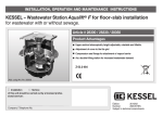
2.2 Kabelanschluss
Die Steuerleitungen für Sonde und
Antriebsmotor durch das Kabelleerrohr
ziehen. Gegebenenfalls die Leitungen für
den externen Signalgeber und den potentialfreien Kontakt verlegen. Anschließend
am Schaltgerät den Motorstecker (grau,
Bild1) und den Sensorstecker (weiß, Bild
2) entsprechende den Markierungen (Bild
3) aufstecken und handfest verschrauben
(1 Nm).
Bitte beachten:
Stecker grau auf Buchse grau
Stecker weiß auf Buchse weiß
Bild 1, grau
Bild 2, weiß
Hinweis zum Kabelschutz
Bei freiverlegten Sonden- und Motorkabel
ist vor Verbiß von Ungeziefer zu schützen.
Ein entsprechender Schutzmantel ist über
den KESSEL-Kundendienst erhältlich.
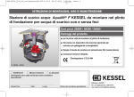
2.3 Anschluss Antriebsmotor (Bild 4)
Bild 4
Bild 3
Die abgeflachte Antriebswelle des Motors
muss sich in senkrechter Stellung befinden (Auslieferungszustand). Den Verriegelungshebel des Betriebsverschlusses
auf dem Verriegelungsdeckel in die Stellung „ZU“ bringen, den Antriebsmotor von
oben kommend seitlich in die Antriebsnut
einschieben und mit den vier Schrauben
M5 x 12 (TX25) auf dem Verriegelungsdeckel anschrauben.
4
HINWEIS:
Die Vorschriften der VDE 0100, VDE
01107, IEC, bzw. der örtlichen EVU (Energie-Versorgungsunternehmen) sind
zu beachten.
Das Schaltgerät darf nicht in explosionsgefährdeten Räumen installiert
werden.
2. Elektroanschluss
2.4 Sondenanschluss
Die optische Sonde wird im FKA-Verriegelungsdeckel montiert. Dazu wird der
Blindstopfen (lila) entfernt und die Sonde
mit beiliegenden Schrauben handfest angeschraubt (2 Schrauben M5 x12 (TX25))
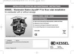
2.8 Anschlussplan Schaltgerät Standard
2.5 Externer Signalgeber
Der externe Signalgeber (Best.Nr. 20162)
zur Übertragung des Warntons in andere
Räume kann nach Bedarf angeschlossen
werden.
Bild 5
1 2 3 1 23
2.9 Anschlussplan Schaltgerät Comfort
2.6 Potentialfreier Kontakt
Optional kann eine Zusatzplatine mit
einem potentialfreien Kontakt (Best.Nr.
80072) an die zentrale Leittechnik des
Gebäudes angeschlossen werden. Anschluss siehe Beiblatt potentialfreier Kontakt. Jeder Alarm wird bei Rückstau oder
einer Störung über den potentialfreien
Kontakt gemeldet. Bei Klappenprüfung
(Tastenfunktion „Klappe Test“) erfolgt eine
Alarmmeldung über den potentialfreien
Kontakt, wenn die Klappe die Endlage
“zu” erreicht.
2.7 Verlängerung der Steuerleitungen
Werden mehr als 5 m Kabellänge
benötigt, so gibt es hierfür 10m-Verlängerungen (Art.-Nr. 80889 Sonde, Art.-Nr.
80890 Motor).
Die maximale Leitungslänge von 30 m
darf nicht überschritten werden.
5
3. Inbetriebnahme Standard
3.1 Schaltgerät
d
Zur Inbetriebnahme muss das Schaltgerät nicht mehr geöffnet werden.
Die im Lieferumfang enthaltenen Batterien
sind bereits angeschlossen und werden
beim ersten 230V-Netzanschluss aktiviert.
Die Netzleitung anschließen. Das Schaltgerät führt einen Grundfunktionstest, die
sog. Initialisierung durch. Dies wird durch
ein Lauflicht ca. 8 sec. nach Anstecken der
Batterie, bzw. des Netzsteckers angezeigt.
Bei der Initialisierung werden Batterie-,
Netz-, Sonden- und Motoranschluss überprüft und der Betriebsverschluss (je nach
Stellung) einmal komplett geschlossen
und wieder geöffnet.
Bei korrektem Anschluss des Schaltgerätes leuchtet anschließend die Power-LED
(grün). Der Rückstauautomat StaufixFKA
ist jetzt betriebsbereit.
Nach der Inbetriebnahme muss der Not-
a
e
f
k
g
hl
b
c
i
j
verschluss (roter Hebel Auslaufseite) von
Hand geöffnet werden. Die Funktionsprüfung nach DIN EN 13564 und die Prüfung
3.2 Funktionsprüfung nach DIN EN 13564
der Sonde sind durchzuführen (siehe Anleitung StaufixFKA)
3.3 Prüfung der optischen Sonde
➁
Verschlussschraube R1/2”
➀
➂
Betriebsverschluss (4) mittels Prüftaste
schließen. Den Notverschluss (3) mit
dem Handhebel verschließen.
Die Verschlussschraube R1/2“ (1) vom
Deckel entfernen und den Trichter (2) anschrauben.
Klarwasser
einfüllen,
bis
eine
Prüfdruckhöhe von mindestens 10 cm
erreicht ist.Die Wasserspiegelhöhe (=
Prüfdruckhöhe) im Trichter ist 10 Minuten
zu beobachten und gegebenenfalls
a) Gehäuse Schaltgerät
b) Verschlussschraube
c) Netzanschlussleitung
d) Kurzbedienungsanleitung
e) grüne LED „Power“
f) rote LED „Alarm“
g) orange LED “Rückstau”
h) orange LED “Klappe”
i) Anschluss Motor (grau)
j) Anschluss optische Sonde (weiß)
k) Alarm-Taste
l) Test-Taste
➃
durch Nachfüllen auf der ursprünglichen
Höhe zu halten. Der Rückstauverschluss
gilt als dicht, wenn in dieser Zeit nicht
mehr als 500 ccm Wasser nachgefüllt
werden muss.
Nach der Prüfung den Notverschluss (3)
wieder öffnen. Den Trichter (2) entfernen
und die Verschlussschraube (1) mit dem
Dichtring in den Deckel einschrauben.
Den Betriebsverschluss (4) mit der
Prüftaste wieder öffnen.
6
Schrauben entfernen. Die Sonde aus dem
Deckel ziehen. Die Sonde in Wasser eintauchen. Der Betriebsverschluss muss
schließen, die optische und akustische
Warneinrichtung muß ansprechen. Sobald
die Sonde aus dem Wasser genommen
wird, muss der Betriebsverschluss öffnen
und das optische und akustische Signal erlöschen.
Die Sonde mit der Dichtung in den Deckel
einschieben und mit den Schrauben befestigen.
Achtung: Nach jeder Wartung mit der
“Prüfen”-Taste auf volle Funktionalität prüfen. Beide Klappen prüfen, sie müssen
beide auf betriebsbereiten Zustand gestellt
sein.
4. Betrieb Standard Schaltgerät
4.1 Betriebsfälle
Betriebsbereitschaft
Rückstau Klappe schließt
Power-LED
Alarm-LED
Power-LED
Alarm-LED
Rückstau-LED
Klappe-LED
Klappe ist geschlossen Power-LED
Alarm-LED
Rückstau-LED
Klappe-LED
Signalton
grün
rot
Netzbetrieb
grün
rot
orange
orange
leuchtet
aus
blinkt
leuchtet
Intervallton
grün
rot
orange
orange
Der Alarm kann mit der Prüftaste quittiert werden, d. h. der
Alarmton wird während der Dauer des Rückstaus ausgeschaltet.
leuchtet
aus
leuchtet
aus
blinkt
blinkt
Alarm-Taste
Der Alarm kann durch Drücken der Alarmtaste quittiert werden. Die Alarm-LED
blinkt und zeigt dem Betreiber somit an,
daß der Fehler weiterhin besteht.
Wenn die Alarmtaste 5 Sekunden lang
gedrückt wird, führt das Schaltgerät einen
automatischen Neustart durch. Das
Schaltgerät muss dafür nicht extra vom
Netz gertrennt (Netzstecker gezogen)
werden. Das hat vor allem dann Vorteile,
wenn das Schaltgerät ohne Stecker, direkt verdrahtet, ans Netz angeschlossen
ist.
Prüftaste (TEST)
Der Betriebsverschluss kann, z. B. für die
Wartung manuell betätigt werden. Durch
einmaliges Drücken wird die Klappe geschlossen.
Durch nochmaliges Drücken wird die
Klappe wieder geöffnet.
Das Schließen und Öffnen der Klappe
wird durch das Blinken, die geschlossene
Klappe durch Leuchten der Klappen-LED
angezeigt. Bei geschlossener Klappe ertönt ein akkustisches Signal (Alarm).
aus
blinkt (1 sec. Takt)
aus
aus
aus
blinkt (1 sec. Takt)
aus
aus
blinkt
aus
Intervallton
Im Batteriebetrieb wird der Rückstau jetzt durch Blinken
der Rückstau-LED im Sekundentakt angezeigt; alle anderen optischen Anzeigen bleiben aus.
Im Netzbetrieb wird dies durch das Blinken der Alarm-LED
angezeigt. Alle anderen optischen Anzeigen ändern sich
nicht.
4.2 Funktionstasten
Batteriebetrieb
Achtung: Klappe öffnet nicht selbsttätig!
Tritt während des Schließens der Klappe
ein Rückstau auf, wird dieser durch das
Blinken der Rückstau-LED angezeigt, sobald die Klappe vollständig geschlossen
ist.
Achtung: Das Ende des Rückstaus wird
durch das Erlöschen der Rückstau-LED
angezeigt (nur optische Anzeige!). Der
Alarmton ändert sich nicht mehr.
Während des Rückstaus kann die Klappe
nicht manuell geöffnet werden!
lm Batteriebetrieb kann die Prüftaste
nicht aktiviert werden, zur Schonung der
Batterien!
4.3 Ausserbetriebnahme
Achtung:
Nach Ziehen des Netzsteckers muss die
-Alarm-Taste min. 5 sec gedrückt
werden bis der Signalton ertönt. Dies
dient zur Schonung der Batterie!
7
5. Fehlererkennung Standard Schaltgerät
Mit dem KESSEL-Schaltgerät können Fehler bei der Inbetriebnahme sowie während des Betriebs erkannt und somit leicht abgestellt
werden.
5.1 Störungen bei Netzbetrieb:
Fehleranzeige
Power-LED blinkt,
Alarm-LED blinkt
Signalton
Ursache
Batterie fehlt oder ist defekt
“Batteriefehler”
Netzstecker ziehen, Batterien
anschließen, ggf. durch neue Batterien ersetzen
Die Funktionsbereitschaft des
Gerätes wird durch ein erneutes
Lauflicht angezeigt.
Power-LED leuchtet
Alarm-LED blinkt
schnell
Klappe-LED blinkt
Signalton
- Initialisierung: Steuerleitung „Motor“ nicht angeschlossen, verpolt oder gebrochen
- Im Betrieb: Steuerleitung
„Motor“ defekt
“Motorfehler”
Netzstecker ziehen, Batterie abklemmen; Steuerleitung auf korrekten Anschluß, bzw. Durchgang kontrollieren, ggf. Motor austauschen.
Power-LED leuchtet
Alarm-LED blinkt
schnell
Rückstau-LED blinkt
Signalton
Power-LED leuchtet
Alarm-LED blinkt
Klappe-LED blinkt,
Signalton
- Initialisierung: Steuerleitung „Sonde“ nicht angeschlossen, verpolt oder gebrochen
- Im Betrieb: Steuerleitung
„Sonde“ defekt
Sondenfehler”
Klappe kann bei der Inbetriebnahme, bzw. durch die
„Prüfen“-Taste nicht vollständig geschlossen werden, d.
h. die Klappe wird durch
einen Gegenstand im Rückstauverschluss blockiert
“Klappenfehler”
- Falsche Hebelposition bei
Deckelverbau
Abstellmaßnahme
Netzstecker ziehen, Batterie deaktivieren; Steuerleitung auf korrekten Anschluß, bzw. Durchgang kontrollieren; ggf. Sonde austauschen.
Netzstecker ziehen, Batterie deaktivieren; Staufix-Deckel öffnen,
Blockierung beseitigen und Anlage
erneut in Betrieb nehmen
Empfehlung:
Fachbetrieb informieren
- Siehe EBA 010-842 (Punkt 4.2.1)
Power-LED leuchtet, -Rückstau wurde erkannt.
-Notverschluss schließen. Nach
Alarm-LED blinkt,
Die Klappe kann aber nicht Rückstauende Blockierung wie beRückstau-LED blinkt vollständig
geschlossen schrieben entfernen
Klappe-LED blinkt
werden, d. h. sie wird durch
Signalton
einen Gegenstand blockiert
“Klappenfehler bei Rückstau”
Power-LED leuchtet
Alarm-LED blinkt
abwechselnd mit
Klappe-LED
Power-LED leuchtet
Alarm-LED blinkt
gleichzeitig mit
Klappe-LED
Max. Zyklenzahl
Klappe überschritten
Motor tauschen
Grenzlaufzahl Motor
überschritten
Kundendienstpartner
informieren
8
Hinweise
- Initialisierung: Die Anlage kann in
Betrieb genommen werden, d. h. sie
ist funktionsfähig. Alarm kann quittiert werden.
- Betrieb: Die Fehlermeldung wird
spätestens nach 5 Min. angezeigt.
Die Anlage ist funktionsbereit; Handbetrieb ist möglich.
Fehlererkennung erfolgt nur im Betrieb (siehe dazu Kap. 8.2 „Zusatzfunktionen“).
- Initialisierung: Inbetriebnahme
nicht möglich
- Im Betrieb: Fehlererkennung bei
Handbetrieb Prüfzyklus/Rückstau
Die Abfrage der Sondenleitung erfolgt alle 2 sec.
Achtung: BetriebsverschlussStellung prüfen! Die Steuerung
versucht 3 x im Intervall die Klappe
zu schließen und dabei den
blockierenden Gegenstand evtl. zu
beseitigen. Kann durch die Klappenbewegung der Gegenstand
während dieser Zyklen entfernt
werden, ist die Anlage wieder funktionsfähig. Gelingt dies nicht, geht
die Anlage auf Störung. Die Quittierung des akustischen Signals ist
möglich. Es ist auch möglich, daß
der Gegenstand durch Spülen der
Leitung entfernt werden kann.
Durch anschließendes Drücken der
Prüftaste kann dies überprüft werden. Bei negativem Ergebnis tritt die
Fehlermeldung erneut auf; der Gegenstand ist wie unter Abstellmaßnahme beschrieben zu beseitigen.
Lebensdauer Motor erreicht
Klappe schließt zu häufig in
kurzer Zeit
5. Fehlererkennung Standard Schaltgerät
5.2 Störungen bei Batteriebetrieb / Netzausfall:
Fehleranzeige
Ursache
Abstellmaßnahme
Hinweise
Alarm-LED blinkt
schnell
Gerät ist im Batteriebetrieb; Netzspannung kontrollieren, ggf.
Netzspannung fehlt
wiederherstellen
Power-LED
blinkt schnell,
Alarm-LED
blinkt schnell
Klappe-LED
blinkt schnell
Signalton
- Im Betrieb: Steuerleitung Batterie deaktivieren; Steuerleitung
oder „Motor“ defekt
auf korrekten Anschluss, bzw.
Durchgang kontrollieren;
ggf. Motor austauschen.
Fehlererkennung erfolgt nur im Betrieb
- Im Betrieb: Steuerleitung Batterie deaktivieren; Steuerleitung
oder „Sonde“ defekt
auf korrekten Anschluss, bzw.
Durchgang kontrollieren;
ggf. Sonde austauschen
Die Abfrage der Sondenleitung erfolgt alle 60 sec.
Klappe-LED
blinkt schnell
Alarm-LED
blinkt schnell
Klappe kann nicht vollständig geschlossen werden,
d. h. die Klappe wird durch
einen Gegenstand im Rückstauverschluss blockiert
Power-LED
blinkt schnell,
Alarm-LED
blinkt schnell
Rückstau-LED
blinkt schnell
Signalton
Alarm-LED
blinkt schnell
Rückstau-LED s
blinkt schnell
Klappe-LED
blinkt schnell
Signalton
Die Anlage ist 2 Stunden funktionsfähig. Anschließend geht das Gerät
in den Sleep-Modus (siehe Kap. 6.3
Zusatzfunktionen)
Netzstecker ziehen, Batterie abklemmen; Staufix-Deckel öffnen,
Blockierung beseitigen und Anlage
erneut in Betrieb nehmen
Rückstau wurde erkannt.
Notverschluss schließen. Nach
Die Klappe kann aber nicht Rückstauende Blockierung wie bevollständig geschlossen wer- schrieben entfernen
den, d. h. sie wird durch
einen Gegenstand blockiert
9
Achtung: BetriebsverschlussStellung prüfen! Die Steuerung
versucht 3 x im Intervall die Klappe
zu schließen und dabei den blockierenden Gegenstand evtl. zu beseitigen. Kann durch die Klappenbewegung der Gegenstand während dieser Zyklen entfernt werden, ist die
Anlage wieder funktionsfähig. Gelingt dies nicht, geht die Anlage auf
Störung. Die Quittierung des Signals
ist möglich.
Es ist auch möglich, das der Gegenstand durch Spülen der Leitung entfernt werden kann. Durch anschließendes Drücken der Prüftaste
kann dies überprüft werden. Bei negativem Ergebnis tritt die Fehlermeldung erneut auf; der Gegenstand ist
wie unter Abstellmaßnahme beschrieben zu beseitigen.
6. Inbetriebnahme Comfort
6.1 Schaltgerät
Zur Inbetriebnahme muss das Schaltgerät nicht mehr geöffnet werden.
Die im Lieferumfang enthaltenen Batterien
sind bereits angeschlossen und werden
beim ersten 230V-Netzanschluss aktiviert.
Die Netzleitung anschließen. Das Schaltgerät führt einen Grundfunktionstest, die
sog. Initialisierung durch. Dies wird durch
ein Lauflicht ca. 8 sec. nach Anstecken der
Batterie, bzw. des Netzsteckers angezeigt.
Bei der Initialisierung werden Batterie-,
Netz-, Sonden- und Motoranschluss überprüft und der Betriebsverschluss (je nach
Stellung) einmal komplett geschlossen
und wieder geöffnet.
Bei korrektem Anschluss des Schaltgerätes leuchtet anschließend die Power-LED
(grün). Der Rückstauautomat StaufixFKA
ist jetzt betriebsbereit.
l
a
b
h i
c
m
Nach der Inbetriebnahme muss der Notverschluss (roter Hebel Auslaufseite) von
Hand geöffnet werden. Die Funktionsprü-
6.2 Funktionsprüfung nach DIN EN13564
fung nach DIN EN 13564 und die Prüfung
der Sonde sind durchzuführen (siehe Anleitung StaufixFKA).
6.3 Prüfung der optischen Sonde
➁
Verschlussschraube R1/2”
➀
➂
Betriebsverschluss (4) mittels Prüftaste
schließen. Den Notverschluss (3) mit
dem Handhebel verschließen.
Die Verschlussschraube R1/2“ (1) vom
Deckel entfernen und den Trichter (2) anschrauben.
Klarwasser
einfüllen,
bis
eine
Prüfdruckhöhe von mindestens 10 cm
erreicht ist. Die Wasserspiegelhöhe (=
Prüfdruckhöhe) im Trichter ist 10 Minuten
zu beobachten und gegebenenfalls
d
e
j
f
g
k
a) Gehäuse Schaltgerät
b) Verschlussschraube
c) Netzanschlussleitung
d) grüne LED „Power“
e) rote LED „Alarm“
f) orange LED “Rückstau”
g) orange LED “Klappe”
h) Anschluss Motor (grau)
i) Anschluss optische Sonde (weiß)
j) Alarm-Taste
k) Test-Taste
l) Displayanzeige
m) Funktionstasten für
Displayanzeige
➃
durch Nachfüllen auf der ursprünglichen
Höhe zu halten. Der Rückstauverschluss
gilt als dicht, wenn in dieser Zeit nicht
mehr als 500 ccm Wasser nachgefüllt
werden muss.
Nach der Prüfung den Notverschluss (3)
wieder öffnen. Den Trichter (2) entfernen
und die Verschlussschraube (1) mit dem
Dichtring in den Deckel einschrauben.
Den Betriebsverschluss (4) mit der
Prüftaste wieder öffnen.
10
Schrauben entfernen. Die Sonde aus dem
Deckel ziehen. Die Sonde in Wasser eintauchen. Der Betriebsverschluss muss
schließen, die optische und akustische
Warneinrichtung muß ansprechen. Sobald
die Sonde aus dem Wasser genommen
wird, muss der Betriebsverschluss öffnen
und das optische und akustische Signal erlöschen.
Die Sonde mit der Dichtung in den Deckel
einschieben und mit den Schrauben befestigen.
Achtung: Nach jeder Wartung mit der
“Prüfen”-Taste auf volle Funktionalität prüfen. Beide Klappen prüfen, sie müssen
beide auf betriebsbereiten Zustand gestellt
sein.
7. Betrieb Comfort Schaltgerät
7.1 Betriebsfälle Diodenanzeige
Betriebsbereitschaft
Rückstau Klappe schließt
Power-LED
Alarm-LED
Power-LED
Alarm-LED
Rückstau-LED
Klappe-LED
Klappe ist geschlossen Power-LED
Alarm-LED
Rückstau-LED
Klappe-LED
Signalton
Der Alarm kann mit der Prüftaste quittiert
werden, d. h. der Alarmton wird während
der Dauer des Rückstaus ausgeschaltet.
Im Netzbetrieb wird dies durch das Blinken der Alarm-LED angezeigt. Alle anderen optischen Anzeigen ändern sich nicht.
Im Batteriebetrieb wird der Rückstau jetzt
durch Blinken der Rückstau-LED im Sekundentakt angezeigt; alle anderen optischen Anzeigen bleiben aus.
7.2 Funktionstasten Gerät
Alarm-Taste
Der Alarm kann durch Drücken der AlarmTaste quittiert werden. Die Alarm-LED
blinkt und zeigt dem Betreiber somit an,
daß der Fehler weiterhin besteht.
Netzbetrieb
Batteriebetrieb
grün
rot
leuchtet
aus
aus
blinkt (1 sec. Takt)
grün
rot
orange
orange
leuchtet
aus
blinkt
leuchtet
Intervallton
aus
aus
blinkt
aus
Intervallton
grün
rot
orange
orange
leuchtet
aus
blinkt
blinkt
Blinken der Rückstau-LED angezeigt,
sobald die Klappe vollständig geschlossen ist. Außerdem ertönt ein Alarmton.
Während des Rückstaus kann die Klappe
nicht manuell geöffnet werden!
Achtung: Das Ende des Rückstaus wird
durch das Erlöschen der Rückstau-LED
angezeigt (nur optische Anzeige!). Der
Alarmton ändert sich nicht mehr.
Die Klappe kann über die Prüftaste wieder geöffnet werden.
lm Batteriebetrieb kann die Prüftaste
nicht aktiviert werden, zur Schonung der
Batterien!
Prüftaste (TEST)
Der Betriebsverschluss kann, z. B. für die
Wartung manuell betätigt werden. Durch
einmaliges Drücken wird die Klappe geschlossen.
Durch nochmaliges Drücken wird die
Klappe wieder geöffnet.
Das Schließen und Öffnen der Klappe
wird durch das Blinken, die geschlossene
Klappe durch Leuchten der Klappen-LED
angezeigt. Bei geschlossener Klappe ertönt ein akkustisches Signal (Alarm).
aus
aus
aus
blinkt (1 sec. Takt)
7.3 Ausserbetriebnahme
Achtung:
Nach Ziehen des Netzsteckers muss die
-Alarm-Taste min. 5 sec gedrückt werden bis der Signalton ertönt. Dies dient
zur Deaktivierung der Batterie!
Alarm-Taste
Test-Taste
Achtung: Klappe öffnet nicht selbsttätig!
Tritt während des Schließens der Klappe
ein Rückstau auf, wird dieser durch das
11
7. Betrieb Comfort Schaltgerät
7.4 Displayanzeigen
7.4.1 Erstinbetriebnahme
b) Mit den Pfeiltasten “Tag” einstellen, mit der OK-Taste bestätigen. Der Cursor springt
zum Feld “Monat”. Diese
und weitere Einstellungen
erfolgen ebenso. Es erscheint der Startbildschirm
a) Bei Erstinbetriebnahme erscheint Bild 3.5.1. Mit den
Pfeiltasten wählen Sie die
entsprechende Menüsprache, mit der OK-Taste bestätigen.
7.4.2 Funktions- und Bedienschema
Displayaufbau:
Nummerierung des
ausgewählten Menüpunktes
übergeordnete Ebene
ausgewählter Menüpunkt
Piktogramm des
ausgewählten Menüpunktes
Das Steuergerät lässt sich intuitiv mit Hilfe der Menütasten bedienen. Das Displaymenü ist in drei Ebenen aufgeteilt, z. B.:
1. Hauptmenü
1.1 Untermenü
1.1.1 Zweite Untermenüebene
1.1.1 Wertanzeige des zweiten Untermenüs
Menütasten
- Mit “OK” wird Eingabe bestätigt bzw. man kommt in die nächste Unterebene des Menüs.
- Mit “ESC” verlässt man die aktuelle Menüebene und kommt in die nächst höhere Ebene.
- Mit den Pfeilasten ▲ ▼ bewegt man sich in einer Menüebene und kann den entsprechenden
Menüpunkt anwählen; diesen dann mit “OK” auswählen.
12
7. Betrieb Comfort Schaltgerät
7.4.3 Menüerklärung
Displayanzeige
Beschreibung
Information
Bildschirmanzeige im
Betriebszustand
Beim Drücken einer Displaymenütaste
schaltet sich die Displaybeleuchtung ein
Das Menü besteht aus
3 Hauptmenüpunkten
1. Information
2. Wartung
3. Einstellungen
Der Hauptmenüpunkt Information
besteht 5 Untermenüpunkten.
Hier können Werte abgefragt, jedoch
nicht verändert werden
1.1 Betriebsstunden
1.2 Logbuch
1.3 Steuerungstyp
1.4 Wartungstermin
1.5 Parameter
Durch Drücken von “OK” wird die
entsprechende Zeit/Anzahl angezeigt
1.1.1 Gesamtlaufzeit
1.1.2 Rückstauzeit
1.1.3 Rückstauanzahl
1.1.4 Schaltspiel Klappe 1
1.1.5. Schaltspiel Klappe 2
1.1.6 Netzausfall
Gesamtlaufzeit des Fäkalienrückstauautomaten FKA
Anzeige der Gesamtbetriebszeit-Schaltgerät
Gesamte Rückstauzeit wird
angezeigt
Summe aller Rückstauzeiten
Alle Rückstauereignisse werden angezeigt
Summe aller Sondenmeldungen
13
7. Betrieb Comfort Schaltgerät
Displayanzeige
Beschreibung
Information
Nicht belegt
Nicht belegt
Alle Netzausfälle seit
Inbetriebnahme werden angezeigt
Summe aller Netzausfälle
Im Logbuch sind die letzten Ereignisse und Fehlermeldungen gespeichert.
Mithilfe der ▲
▼ -Tasten
durchzublättern.
255 Einträge werden gespeichert. Darüberhinaus wird immer der älteste überschrieben.
Gerätespezifikation wird angezeigt
Hardware und Softwareanzeige
Alle Klappenschaltspiele werden
angezeigt
Summe aller Schließvorgänge
Mit “OK” wird der letzte Wartungstermin angezeigt
Mit “OK” wird der nächste Wartungstermin angezeigt
14
Halbjährliche Wartung ist vorgeschrieben
7. Betrieb Comfort Schaltgerät
Displayanzeige
Beschreibung
Es werden 8 Parameter angezeigt
Einschaltverzögerung nach
Stromausfall
Information
1.5.1 Netz Ein. Verz.
1.5.2 Einschaltsper.
1.5.3 Einsch. Verz. 1
1.5.4 Nachlaufzeit 1
1.5.5 Max. Zyklen Klappe 1
1.5.6 Max. Strom Klappe 1
1.5.7 Grenzlaufzahl
1.5.8 Systemdiagnose SDS
Defaultwert sind 2 sec.
Nicht belegt
Nicht belegt
Die Einschaltverzögerung
Motorklappe wird angezeigt
Defaultwert sind 2 sec.
nicht belegt
nicht belegt
Die maximalen Klappenzyklen
werden angezeigt
Defaultwert sind 5000 Schliessvorgänge.
Dann Alarmmeldung “Motor wechseln”
Der maximale Stromaufnahmewert
des Motors wir angezeigt
15
7. Betrieb Comfort Schaltgerät
Displayanzeige
Beschreibung
Information
Die maximale Anzahl von
Motorklappenschliessungen in einem
bestimmten Zeitraum wird angezeigt.
Defaultwert ist 30.
Der Zeitraum zwischen zwei Selbstdiagnosetests (SDS) wird angezeigt.
Defaultwert sind 28 Tage.
Der Hauptmenüpunkt Wartung ist
passwortgeschützt. Hier können
Werte geändert werden.
Der Zugang ist nur
KESSEL-Kundendienstpartnern möglich.
Der Hauptmenüpunkt Einstellungen
besteht aus sieben Untermenüpunkten. 3.1, 3.2, 3.4, 3.6 sind passwortgeschützt.
Im restlichen Bereich können Werte
geändert werden.
3.3 Datum /Uhrzeit
3.5 Sprache
3.7 Kontrast
Hier können Einstellungen vorgenommen
werden. Der Zugang der passwortgeschützten
Untermenüs ist nur KESSEL-Kundendienstpartnern möglich.
Hier können Datum und Uhrzeit eingestellt wertden.
Siehe 7.4.1 Erstinbetriebnahme
Hier kann eine Menüsprache ausgewählt werden.
Siehe 7.4.1 Erstinbetriebnahme
Hier kann der Displaykontrast eingestellt werden.
Einstellbereich 5-20. Defaultwert ist 14.
16
8. Fehlererkennung Comfort Schaltgerät
Mit dem KESSEL-Schaltgerät können Fehler bei der Inbetriebnahme sowie während des Betriebs erkannt und somit leicht abgestellt
werden.
8.1 Störungen bei Netzbetrieb ➤ Diodenanzeige
Fehleranzeige
Power-LED blinkt,
Alarm-LED blinkt
Signalton
Ursache
Batterie fehlt oder ist defekt
“Batteriefehler”
Netzstecker ziehen, Batterien
anschließen, ggf. durch neue Batterien ersetzen
Die Funktionsbereitschaft des
Gerätes wird durch ein erneutes
Lauflicht angezeigt.
Power-LED leuchtet
Alarm-LED blinkt
schnell
Klappe-LED blinkt
Signalton
- Initialisierung: Steuerleitung „Motor“ nicht angeschlossen, verpolt oder gebrochen
- Im Betrieb: Steuerleitung
„Motor“ defekt
“Motorfehler”
Netzstecker ziehen, Batterie abklemmen; Steuerleitung auf korrekten Anschluß, bzw. Durchgang kontrollieren, ggf. Motor austauschen.
Power-LED leuchtet
Alarm-LED blinkt
schnell
Rückstau-LED blinkt
Signalton
Power-LED leuchtet
Alarm-LED blinkt
Klappe-LED blinkt,
Signalton
- Initialisierung: Steuerleitung „Sonde“ nicht angeschlossen, verpolt oder gebrochen
- Im Betrieb: Steuerleitung
„Sonde“ defekt
Sondenfehler”
Klappe kann bei der Inbetriebnahme, bzw. durch die
„Prüfen“-Taste nicht vollständig geschlossen werden, d.
h. die Klappe wird durch
einen Gegenstand im Rückstauverschluss blockiert
“Klappenfehler”
- Falsche Hebelposition bei
Deckelverbau
Abstellmaßnahme
Netzstecker ziehen, Batterie deaktivieren; Steuerleitung auf korrekten Anschluß, bzw. Durchgang kontrollieren; ggf. Sonde austauschen.
Netzstecker ziehen, Batterie deaktivieren; Staufix-Deckel öffnen,
Blockierung beseitigen und Anlage
erneut in Betrieb nehmen
Empfehlung:
Fachbetrieb informieren
- Siehe EBA 010-842 (Punkt 4.2.1)
Hinweise
- Initialisierung: Die Anlage kann in
Betrieb genommen werden, d. h. sie
ist funktionsfähig. Alarm kann quittiert werden.
- Betrieb: Die Fehlermeldung wird
spätestens nach 5 Min. angezeigt.
Die Anlage ist funktionsbereit; Handbetrieb ist möglich.
Fehlererkennung erfolgt nur im Betrieb (siehe dazu Kap. 8.2 „Zusatzfunktionen“).
- Initialisierung: Inbetriebnahme
nicht möglich
- Im Betrieb: Fehlererkennung bei
Handbetrieb Prüfzyklus/Rückstau
Die Abfrage der Sondenleitung erfolgt alle 2 sec.
Achtung: BetriebsverschlussStellung prüfen! Die Steuerung
versucht 3 x im Intervall die Klappe
zu schließen und dabei den
blockierenden Gegenstand evtl. zu
beseitigen. Kann durch die Klappenbewegung der Gegenstand
während dieser Zyklen entfernt
werden, ist die Anlage wieder funktionsfähig. Gelingt dies nicht, geht
die Anlage auf Störung. Die Quittierung des akustischen Signals ist
möglich. Es ist auch möglich, daß
der Gegenstand durch Spülen der
Leitung entfernt werden kann.
Durch anschließendes Drücken
der Prüftaste kann dies überprüft
werden. Bei negativem Ergebnis
tritt die Fehlermeldung erneut auf;
der Gegenstand ist wie unter Abstellmaßnahme beschrieben zu
beseitigen.
Power-LED leuchtet,
Alarm-LED blinkt,
Rückstau-LED blinkt
Klappe-LED blinkt
Signalton
Notverschluss schließen. Nach
Rückstau wurde erkannt.
Die Klappe kann aber nicht Rückstauende Blockierung wie bevollständig geschlossen wer- schrieben entfernen
den, d. h. sie wird durch
einen Gegenstand blockiert
“Klappenfehler bei Rückstau”
Power-LED leuchtet
Alarm-LED blinkt
abwechselnd mit
Klappe-LED
Max. Zyklenzahl
Klappe überschritten
Motor tauschen
Lebensdauer Motor erreicht
Grenzlaufzahl Motor
überschritten
Kundendienstpartner
informieren
Klappe schließt zu häufig in
kurzer Zeit
Power-LED leuchtet
Alarm-LED blinkt
gleichzeitig mit
Klappe-LED
17
8. Fehlererkennung Comfort Schaltgerät
8.2 Störungen bei Netzbetrieb ➤ Displayanzeige
Displayanzeige
Ursache
Abstellmaßnahme
Batterie fehlt oder ist Netzstecker ziehen, Batterien
anschließen, ggf. durch neue
defekt
Batterien ersetzen
“Batteriefehler”
Die Funktionsbereitschaft des
Gerätes wird durch ein erneutes
Lauflicht angezeigt.
Hinweise
- Initialisierung: Die Anlage kann in
Betrieb genommen werden, d. h. sie ist
funktionsfähig. Alarm kann quittiert werden. - Betrieb: Die Fehlermeldung
wird spätestens nach 5 Min. angezeigt.
Die Anlage ist funktionsbereit; Handbetrieb ist möglich.
- Initialisierung: Steuerleitung „Motor“ nicht
angeschlossen, verpolt
oder gebrochen
- Im Betrieb: Steuerleitung „Motor“ defekt
“Motorfehler”
Netzstecker ziehen, Batterie abklemmen; Steuerleitung auf korrekten Anschluß, bzw. Durchgang kontrollieren, ggf. Motor
austauschen.
Klappe kann bei der Inbetriebnahme, bzw.
durch die „Prüfen“Taste nicht vollständig
geschlossen werden,
d. h. die Klappe wird
durch einen Gegenstand im Rückstauverschluss blockiert
“Klappenfehler”
- Falsche Hebelposition bei Deckelverbau
Netzstecker ziehen, Batterie deaktivieren; Staufix-Deckel öffnen, Blockierung beseitigen und
Anlage erneut in Betrieb nehmen
Max. Zyklenzahl
Klappe überschritten
Motor tauschen
Lebensdauer Motor erreicht
Grenzlaufzahl Motor
überschritten
Kundendienstpartner
informieren
Klappe schließt zu häufig in
kurzer Zeit
- Initialisierung: Steuerleitung „Sonde“ nicht
angeschlossen, verpolt
oder gebrochen
- Im Betrieb: Steuerleitung „Sonde“ defekt
Sondenfehle”
Netzstecker ziehen, Batterie deaktivieren; Steuerleitung auf korrekten Anschluß, bzw. Durchgang kontrollieren; ggf. Sonde
austauschen.
Empfehlung:
Fachbetrieb informieren
- Siehe EBA 010-842 (Punkt
4.2.1)
Rückstau wurde er- Notverschluss schließen. Nach
kannt. Die Klappe kann Rückstauende Blockierung wie
aber nicht vollständig beschrieben entfernen
geschlossen werden, d.
h. sie wird durch einen
Gegenstand blockiert
“Klappenfehler bei Rückstau”
18
Fehlererkennung erfolgt nur im Betrieb (siehe dazu Kap. 8.2 „Zusatzfunktionen“).
- Initialisierung: Inbetriebnahme nicht
möglich
- Im Betrieb: Fehlererkennung bei
Handbetrieb Prüfzyklus/Rückstau
Die Abfrage der Sondenleitung erfolgt
alle 2 sec.
Achtung: Betriebsverschluss-Stellung prüfen! Die Steuerung versucht 3
x im Intervall die Klappe zu schließen und
dabei den blockierenden Gegenstand
evtl. zu beseitigen. Kann durch die Klappenbewegung der Gegenstand während
dieser Zyklen entfernt werden, ist die Anlage wieder funktionsfähig. Gelingt dies
nicht, geht die Anlage auf Störung. Die
Quittierung des akustischen Signals ist
möglich. Es ist auch möglich, daß der Gegenstand durch Spülen der Leitung entfernt werden kann. Durch anschließendes
Drücken der Prüftaste kann dies überprüft
werden. Bei negativem Ergebnis tritt die
Fehlermeldung erneut auf; der Gegenstand ist wie unter Abstellmaßnahme beschrieben zu beseitigen.
8. Fehlererkennung Comfort Schaltgerät
8.3 Störungen bei Batteriebetrieb / Netzausfall ➤ Diodenanzeige
Fehleranzeige
Ursache
Abstellmaßnahme
Hinweise
Alarm-LED blinkt
schnell
Gerät ist im Batteriebetrieb; Netzspannung kontrollieren, ggf.
Netzspannung fehlt
wiederherstellen
Power-LED
blinkt schnell,
Alarm-LED
blinkt schnell
Klappe-LED
blinkt schnell
Signalton
- Im Betrieb: Steuerleitung Batterie deaktivieren; Steuerleitung
oder „Motor“ defekt
auf korrekten Anschluss, bzw.
Durchgang kontrollieren;
ggf. Motor austauschen.
Fehlererkennung erfolgt nur im Betrieb
Power-LED
blinkt schnell,
Alarm-LED
blinkt schnell
Rückstau-LED
blinkt schnell
Signalton
- Im Betrieb: Steuerleitung Batterie deaktivieren; Steuerleitung
oder „Sonde“ defekt
auf korrekten Anschluss, bzw.
Durchgang kontrollieren;
ggf. Sonde austauschen
Die Abfrage der Sondenleitung erfolgt alle 60 sec.
Klappe-LED
blinkt schnell
Alarm-LED
blinkt schnell
Alarm-LED
blinkt schnell
Rückstau-LED s
blinkt schnell
Klappe-LED
blinkt schnell
Signalton
Klappe kann nicht vollständig geschlossen werden,
d. h. die Klappe wird durch
einen Gegenstand im Rückstauverschluss blockiert
Rückstau wurde erkannt.
Notverschluss schließen. Nach
Die Klappe kann aber nicht Rückstauende Blockierung wie bevollständig geschlossen wer- schrieben entfernen
den, d. h. sie wird durch
einen Gegenstand blockiert
Die Anlage ist 2 Stunden funktionsfähig. Anschließend geht das Gerät
in den Sleep-Modus (siehe Kap. 9.3
Zusatzfunktionen)
Netzstecker ziehen, Batterie abklemmen; Staufix-Deckel öffnen,
Blockierung beseitigen und Anlage
erneut in Betrieb nehmen
8.4 Störungen bei Batteriebetrieb / Netzausfall ➤ Displayanzeige
Achtung: BetriebsverschlussStellung prüfen! Die Steuerung
versucht 3 x im Intervall die Klappe
zu schließen und dabei den blockierenden Gegenstand evtl. zu beseitigen. Kann durch die Klappenbewegung der Gegenstand während dieser Zyklen entfernt werden, ist die
Anlage wieder funktionsfähig. Gelingt dies nicht, geht die Anlage auf
Störung. Die Quittierung des Signals
ist möglich.Es ist auch möglich, das
der Gegenstand durch Spülen der
Leitung entfernt werden kann. Durch
anschließendes Drücken der Prüftaste kann dies überprüft werden. Bei
negativem Ergebnis tritt die Fehlermeldung erneut auf; der Gegenstand ist wie unter Abstellmaßnahme beschrieben zu beseitigen.
Bei Netzausfall wird die Displayanzeige deaktiviert – Stromsparmodus. Als Orientierung dient in diesem Falle die
Diodenanzeige.
19
9. Zusatzfunktionen
9.1 Potentialfreier Alarmausgang
Das KESSEL-Schaltgerät für den StaufixFKA kann mit einem Anschluss für einen potentialfreien Kontakt aus-, bzw. nachgerüstet
werden.
Dazu wird nur die Zusatzplatine (Best.Nr.
80072) im Schaltgerät angesteckt und die
gewünschte Steuerleitung an die Anschlussklemmen angeschlossen. Das Relais fällt bei Rückstau sowie bei allen Fehlermeldungen ab; auch beim Betätigen
der Test-Taste.
Achtung: Der potentialfreie Anschluss
ist nur bis 42 V DC/0,5 A zugelassen.
9.2 Automatische Inspektion des Betriebsverschlusses
Alle 4 Wochen wird der Motor automatisch
auf seine Funktion überprüft. Dazu wird
der Betriebsverschluss automatisch geschlossen und wieder geöffnet.
Erkannte Fehler werden mit der entsprechenden Meldung angezeigt und können
dann wie im Kap. 4 beschrieben, beseitigt
werden.
9.3 Sleep-Modus
Befindet sich die Steuerung länger als 2 Stunden im Batteriebetrieb, geht sie in einen sog.
„Sleep-Modus“. Das heißt, die Klappe des Betriebsverschlusses wird automatisch geschlossen. Während des Sleep-Moduses
(Klappe ist geschlossen) wird ein optischer
und akustischer Alarm alle 20 sec. abgegeben
bis die Batterie entladen ist. Gleichzeitig wird
der Alarm auch über den optionalen potentialfreien Kontakt angezeigt. Im Sleep-Modus
befindet sich das Schaltgerät in einer „Ruhestellung“. Sämtliche Anzeigen sind aus. Die
Fehlermeldung über den potentialfreien Kontakt bleibt aber bestehen. Liegt wieder Netzspannung vor, befindet sich die Steuerung sofort wieder im Normalbetrieb.
Mit dieser Funktion wird verhindert, dass die
Batterien völlig entleert werden und dann bei
Stromausfall nicht mehr funktionsfähig sind.
Beispielsweise, wenn die Steuerung während
der Bauphase installiert wird, aber noch keine
durchgehende Netzversorgung vorliegt. In diesem Fall wäre der FKA durch die Batterieversorgung betriebsbereit; die Batterie würde aber
vollkommen entleert werden.
20
9.4 Kontrolle der Batteriespannung
Die Steuerung überprüft konstant die Batteriespannung. Fällt die Batteriespannung
während des Batteriebetriebes unter 13,5
V ab, schließt der Motor den Betriebsverschluss, dieser Fall wird durch kurzes blinken der Power-LED und der Alarm-LED
angezeigt. Bitte überprüfen Sie in beiden
Fällen das Haltbarkeitsdatum an den Batterien und tauschen diese ggf. gegen
Neue aus. Dazu trennen Sie zunächst das
Schaltgerät vom Netz. Anschließend sind
beide Batterie-Anschlußleitungen (siehe
Seite 14) von den Batterien abzustecken,
die Batterien auszutauschen und die
neuen Batterien wieder anzuschließen.
Die gebrauchten Batterien sind fachgerecht zu entsorgen!
Achtung: Bei Verschrottung des
Schaltgerätes sind die Batterien ebenfalls zu entnehmen und entsprechend
fachgerecht zu entsorgen!
Bei neuen Batterien beträgt die Haltbarkeit mind. 2 Jahre.
Für den KESSEL StaufixFKA ist folgende
Batterie zugelassen: Duracell: Size 9V;
Typ MN 1604/6LR61 (Best.Nr. 197-081;
Bedarf: 2 Stück)
10. Technische Daten
Netzspannung (primär)
230 V AC; 50/60 Hz (Eurostecker)
Leistung standby
2,5 W
Potentialfreier Alarmkontakt (Zubehör)
42 V DC / 0,5 A (Umschaltkontakt)
Leistung
5W
0°C bis + 50°C
Einsatztemperatur
Schutzart
IP 54 (Schaltgerät), IP 68, 0,3 bar (Motor, Sonde) 24 h
Schutzklasse
II
Schutzart (Gesamtanlage ohne Schaltgerät)
IP 68 bei max. 3 mWS und max. 24h
21
11. Inspektion und Wartung
11.1 Inspektion
Der Rückstauverschluss ist einmal monatlich vom Betreiber oder dessen Beauftragten zu inspizieren.
Dabei ist folgendes durchzuführen:
1.) Testtaste zur Funktionsprüfung des
Betriebsverschlusses drücken
2.) mehrmaliges Betätigen des Notverschlusses durch schließen und öffnen
11.2 Wartung
11.3 Hinweise zum elektrischen
Schaltgerät
• Die Batterien sind Verschleißteile und
sollten möglichst jährlich überprüft und
gegebenenfalls gewechselt werden.
Beim Wechseln ist auf umweltgerechte
Entsorgung zu achten. Ersatz darf nur
durch gleichen Typ erfolgen.
• Reparaturen dürfen nur durch den Hersteller vorgenommen werden.
ACHTUNG:
Bei allen Wartungsarbeiten, Anlage
stromlos machen! Sicherheitshinweise beachten! Alle nachfolgend beschriebenen Inspektions- und Wartungsarbeiten dürfen nur von autorisiertem Fachpersonal durchgeführt
werden. Reparaturen dürfen nur durch
den Hersteller vorgenommen werden.
Siehe dazu Einbau- und Bedienungsanleitung für FKA-Rückstauautomat (010-842).
22
11.4 Störungen
Sollten nicht behebbare Störungen auftreten, wenden Sie sich bitte im Zweifelsfall an Ihren Fachbetrieb (siehe Stempel
auf Deckblatt), der auch die Installation
durchgeführt hat.
Unsere Kundendienstpartner finden Sie
unter:
www.kessel.de/ewt/kontakt/kundendienst
12. Gewährleistung
1. Ist eine Lieferung oder Leistung mangelhaft, so hat KESSEL nach Ihrer Wahl den
Mangel durch Nachbesserung zu beseitigen oder eine mangelfreie Sache zu liefern.
Schlägt die Nachbesserung zweimal fehl
oder ist sie wirtschaftlich nicht vertretbar, so
hat der Käufer/Auftraggeber das Recht,
vom Vertrag zurückzutreten oder seine
Zahlungspflicht entsprechend zu mindern.
Die Feststellung von offensichtlichen Mängeln muss unverzüglich, bei nicht erkennbaren oder verdeckten Mängeln unverzüglich nach ihrer Erkennbarkeit schriftlich mitgeteilt werden. Für Nachbesserungen und
Nachlieferungen haftet KESSEL in gleichem Umfang wie für den ursprünglichen
Vertragsgegenstand. Für Neulieferungen
beginnt die Gewährleis-tungsfrist neu zu
laufen, jedoch nur im Umfang der Neulieferung.
Es wird nur für neu hergestellte Sachen eine
Gewährleistung übernommen.
Die Gewährleistungsfrist beträgt 24 Monate ab Auslieferung an unseren Vertragspartner. § 377 HGB findet weiterhin Anwendung.
Über die gesetzliche Regelung hinaus erhöht die KESSEL AG die Gewährleistungsfrist für Leichtflüssigkeitsabscheider, Fettabscheider, Schächte, Kleinkläranlagen
und Regenwasserzisternen auf 20 Jahre
bezüglich Behälter. Dies bezieht sich auf
die Dichtheit, Gebrauchstauglichkeit und
statische Sicherheit.
23
Voraussetzung hierfür ist eine fachmännische Montage sowie ein bestimmungsgemäßer Betrieb entsprechend den aktuell
gültigen Einbau- und Bedienungsanleitungen und den gültigen Normen.
2. KESSEL stellt ausdrücklich klar, dass Verschleiß kein Mangel ist. Gleiches gilt für
Fehler, die aufgrund mangelhafter Wartung
auftreten.
Hinweis: Das Öffnen von versiegelten
Komponenten oder Verschraubungen darf
nur durch den Hersteller erfolgen. Andernfalls können Gewährleistungsansprüche
ausgeschlossen sein.
Stand 01. 06. 2010
Führend in Entwässerung
6 4
Privater Wohnungsbau
ohne Kanalanbindung
1 2 3 4
5
1 2 3 4
Öffentlicher Bau
z.B. Krankenhaus
5
Öffentlicher Bau
z.B. Freizeitanlagen
1 2 3 4
5
Gewerblicher Bau
z.B. Hotel
4 5
Gewerblicher Bau
z.B. Industriebau
2 3 5
Gewerblicher Bau
z.B. Tankstellen
1 2 3 4
Privater Wohnungsbau
Ein- und Mehrfamilienhaus
1 Rückstauverschlüsse
2 Rückstauhebeanlagen
3 Hebeanlagen
4 Abläufe / Rinnen
5 Abscheider
6 Kleinkläranlagen
INSTALLATION AND OPERATING MANUAL
Control unit/electric components for KESSEL
automatic backwater valve for wastewater containing sewage
Staufix FKA Standard/Comfort
Product Advantages
Control unit splashwater-proof IP 54
Plug connections for very
straightforward installation
Does not have to be opened for
installation
Does not have to be opened for wall
mounting
Comfort control unit with display
LGA
Landesgewerbeamt Bayern
Bauart
geprüft
und überwacht
heit
cher
ät
mit Si te Qualit
geprüf
Commissioning
Training
This system was installed and commissioned by the following service
company:
Name/Signature
Edition 2014/10
Date
Location
Company Stamp
No. 010-845EN
Subject to technical amendments
Installation
Table of contents
................................................................................................ Page
27
2.1
2.2
2.3
2.4
2.5
2.6
2.7
2.8
2.9
Mounting the control unit on the wall.......................................
Cable connection ....................................................................
Connection of the drive motor .................................................
Probe connection ....................................................................
External signal generator ........................................................
Potential-free switch contact ...................................................
Extending the control cables ...................................................
Connection diagram Standard control unit ..............................
Connection diagram Comfort control unit................................
Page
Page
Page
Page
Page
Page
Page
Page
Page
28
28
28
29
29
29
29
29
29
4.1
4.2
4.3
Working conditions.................................................................. Page
Function keys .......................................................................... Page
Fault detection Standard ........................................................ Page
31
31
31
Safety instructions
1. General
2. Electrical connection
3. Putting the Standard unit
into operation
4. Operating the Standard control unit
3.1
3.2
3.3
5. Fault detection Standard control unit 5.1
5.2
6. Putting the Komfort unit
into operation
7. Operating the Komfort control unit
8. Fault detection Comfort
control unit
9. Additional functions
6.1
6.2
6.3
7.1
7.2
7.3
7.4
7.4.1
7.4.2
7.4.3
8.1
8.2
8.3
8.4
9.1
9.2
9.3
9.4
10. Technical data
11. Service and maintenance
12. Warranty
11.1
11.2
11.3
11.4.
................................................................................................ Page
Control unit.............................................................................. Page
Functional test according to DIN EN 13564 ............................ Page
Testing the optical probe ......................................................... Page
Problems with mains operation of control unit......................... Page
Problems with battery operation/power failure ........................ Page
Control unit.............................................................................. Page
Functional test according to DIN EN 13564 ............................ Page
Testing the optical probe ......................................................... Page
Working conditions diode display ............................................
Device function keys ...............................................................
Putting the unit out of operation ..............................................
Displays...................................................................................
Initial operation........................................................................
Operating panel.......................................................................
Explanation of menu ...............................................................
Problems with mains operation - diode display .......................
Problems with mains operation - display.................................
Problems with battery operation/power failure - diode display
Problems with battery operation/power failure - display..........
Page
Page
Page
Page
Page
Page
Page
Page
Page
Page
Page
27
30
30
30
32
33
34
34
34
35
35
35
36
36
36
37
39
40
41
41
Potential-free alarm output......................................................
Automatic inspection ...............................................................
Sleep mode .............................................................................
Checking the battery voltage...................................................
Page
Page
Page
Page
44
44
44
42
Service ....................................................................................
Maintenance............................................................................
Notes on the electrical control unit ..........................................
Problems .................................................................................
Page
Page
Page
Page
46
46
46
46
................................................................................................ Page
................................................................................................ Page
26
45
47
Safety Instructions
The personnel for assembly, operation,
maintenance and repair must possess the
appropriate qualification for this type of
work. The area of responsibility, the authority and the supervision of staff must be
exactly regulated by the operator.
The operational safety of the system supplied is only guaranteed when it is used in
accordance with the regulations. The limits of the technical specifications may
not be exceeded on any account.
This system contains electric charges and
controls mechanical system components.
Non-compliance with the installation and
operating instructions may result in considerable damage to property, personal
injuries or even fatal accidents.
During assembly, operation, maintenance
and repair of the system, the regulations
for the prevention of accidents, the pertinent DIN and VDE standards and directives, as well as the directives of the local
power supply industry must be heeded.
The system represents one component in
a whole system. Please therefore also
heed the operating instructions for the system as a whole and the individual components. During assembly, maintenance,
service and repair work on one of the
components, the system as a whole must
always be put out of operation and secured against unintentional restart.
The system must not be operated
in potentially explosive areas.
The control unit is live and must not be
opened. Only qualified electricians may
carry out work on electrical facilities. The
term qualified electrician is defined in
VDE 0105.
It must be ensured that the electric cables
as well as all other electrical system components are in a faultless condition. In
case of damage, the system may on no
account be put into operation or must be
stopped immediately.
the manufacturer. For safety reasons, use
original spare parts and accessories approved by the manufacturer. The use of
other parts may void the liability for any
consequences arising thereof.
The unit must be supplied through a residual-current-operated protected device
(RCD) with residual current of not more
than 30 mA.
Caution:
Before any work is started on the
system or on the control unit, it
must be made currentless:
1. Remove the plug from the mains!
2. Keep the alarm key pressed for at
least 5 seconds until the signal sounds
(deactivate the battery function)
Conversions or changes to the system
may only be carried out in agreement with
1. General
Dear customer,
We are pleased that you have decided to buy a KESSEL product.
The entire system was subjected to a stringent quality control before it left our factory. Nevertheless, please check immediately
whether the system has been delivered to you complete and undamaged. In case of any transport damage, please refer to the instructions in the chapter “Warranty” in this manual.
These installation, operating and maintenance instructions contain important information that has to be observed during assembly, operation, maintenance and repair. Prior to carrying out any work on the system, the operator and the responsible technical personnel must carefully read and heed these installation and operating instructions.
The installation of the KESSEL automatic backwater valve for wastewater with sewage Staufix FKA is described in the separate
installation instructions (010-842).
For the operation of this system, these instructions and the instructions with the number 010-842 must be used together!
27
2. Electrical connection
2.1 Mounting the control unit on the
wall
The control unit must be installed dry
and frostproof, preferably in the house,
where any alarms that are given can be
seen or heard. Protect from direct sunlight.
The control unit does not have to be opened
for mounting. Drill two horizontal holes Ø 6
mm at a distance of 168 mm apart (Standard) or 254 mm apart (Komfort). Screw the
2 rounded head screws 4.5 x 35 mm (TX20)
in as far as necessary for the control unit to
be mounted flush to the wall. Make sure
there is enough distance from the wall on the
right to allow the cover to be opened. The
screws, plastic dowels and drilling template
are included in the scope of supply.
2.2 Cable connection
Pull the control cables for probe and drive
motor through the cable conduit. If necessary route the cables for the external signal
generator and the potential-free contact.
Then insert the motor plug (grey, Fig. 1) and
the sensor plug (white, Fig. 2) in the control
unit according to the markings (Fig. 3) and
tighten them by hand (1 Nm).
Please note:
Grey plug to grey socket
White plug to white socket
Fig. 1, grey
Fig. 2, white
Note on cable protection
Where probes and motor cables are exposed, make sure they are protected from vermin bites. A suitable protective sheathing
can be obtained through KESSEL customer
services.
2.3 Connection of the drive motor
(Fig. 4)
Fig. 4
Fig. 3
The levelled drive shaft of the motor must
be in a vertical position (state on delivery).
Move the locking lever of the operating
valve on the locking cover to the “CLOSED” position, insert the drive motor into
the drive groove from above, and screw in
place using the four M5 x 12 screws
(TX25) on the locking cover.
28
NOTE:
The regulations set out by the directives VDE 0100, VDE 01107, IEC or by
the local power supply industry must
be heeded.
The control unit must not be installed
in rooms where there is an explosion
hazard.
2. Electrical connection
2.4 Probe connection
The optical probe is mounted in the FKA
locking cover. For this purpose, the blind
plug (lilac) is removed and the probe is
screwed in place using the enclosed screws (2 M5 x 12 screws (TX25).
2.8 Connection diagram Standard control unit
2.5 External signal generator
The external signal generator (order no.
20162) for transmitting the acoustic warning to other rooms can be connected if
required
Fig. 5
1 2 3 1 23
2.9 Connection diagram Comfort control unit
2.6 Potential-free switch contact
As an option, an additional board with a
potential-free contact (order no. 80072)
can be connected to the central control
technology of the building. For connection
see the leaflet on potential-free contact. In
the event of backwater or a problem,
every alarm is sent via the potential-free
contact. During flap test (key function “flap
test”) an alarm is given via the potentialfree contact when the flap reaches the
final position “closed”.
2.7 Extending the control cables
If more than 5 m cable is required, 10 m
extensions are available (art. no. 80889
probe, art. no. 80890 motor).
The maximum cable length of 30 m must
not be exceeded.
29
3. Putting the Standard unit into operation
3.1 Control unit
The control unit does not have to be
opened for initial operation.
The control unit does not have to be opened for initial operation.
The batteries included in the scope of supply are already connected and are activated the first time the unit is connected to
the 230V mains supply. Connect the
mains cable. The control unit carries out a
basic function test, the so-called initialisation. This is indicated by a running light approx. 8 sec. after the battery or the mains
cable has been inserted.
During initialisation, battery, mains, probe
and motor connection are checked and
the operating valve (depending on the position) closed completely and opened
again once.
When the control unit has been connected
up correctly, the Power-LED (green) lights
up. The automatic backwater valve Stau-
d
a
e
f
k
g
hl
b
c
i
j
fixFKW is now ready for operation.
After the system has been put into operation, the emergency valve (red lever on the
outlet side) has to be opened by hand.
3.2 Functional test according to DIN EN 13564
The functional test in accordance with DIN
EN 13564 and the probe test must be carried out (see instructions for StaufixFKA).
3.3 Testing the optical probe
➁
Screwed
sealing plug
R1/2"
➀
➂
Use the test key to close the operating
valve (4). Close the emergency valve (3)
using the hand lever.
Remove the screwed sealing plug R1/2"
(1) on the cover and screw the funnel (2)
in place.
Fill with clear water until a testing height
of at least 10 cm has been reached.
Observe the water level (= testing pressure height) in the funnel for 10 minutes,
keep to the original level by refilling if ne-
a) Control unit housing
b) Screwed sealing plug
c) Mains cable
d) Brief operating instructions
e) Green LED “Power”
f) Red LED “Alarm”
g) Orange LED “Backwater”
g) Orange LED “Flap”
i) Connection motor (grey)
j) Connection optical probe (white)
k) Alarm key
l) Test key
➃
cessary. The backwater valve is considered watertight if no more than 500 ccm
of water has to be refilled during this time.
After the test, open the emergency valve
(3) again. Remove the funnel (2) and
screw the screwed sealing plug (1) back
into the cover with the sealing ring. Use
the test key to open the operating valve
(4) again.
30
Remove the screws. Pull the probe out of
the cover. Immerse the probe in water. The
operating valve must close, the optical and
acoustic warning devices must trigger. As
soon as the probe is taken out of the water,
the operating valve must open and the optical and acoustic signals must go out.
Push the probe into the cover together with
the seal and fix in place using the screws.
Caution:
Check the system for full functionality after
all servicing work using the “test” key.
Check both valves, they must both be set
to the standby state.
4. Operating the Standard control unit
4.1 Working conditions
Readiness for operation
Backwater Flap closes
Flap is closed
Power-LED
Alarm-LED
Power-LED
Alarm-LED
Backwater-LED
FlapLED
Power-LED
Alarm-LED
Backwater-LED
Flap-LED
Acoustic Alarm
green
red
Mains operation
green
red
orange
orange
lit
off
blinks
lit
Acoustic Alarm
green
red
orange
orange
The alarm can be acknowledged with the test key, i.e. the
alarm signal is switched off during the backwater.
lit
off
lit
off
blinks
blinks
Alarm key
The alarm can be acknowledged by pressing the alarm key. The alarm-LED flashes and thus indicates to the operator that
the fault is still pending.
When the Alarm button on the control unit
can be pressed for 5 seconds which will
automatically re-boot the control unit. This
especially is advantageous if the control
unit is hard-wired into the wall (without a
plug to pull out).
Test key (TEST)
The operating valve can be actuated manually e.g. for maintenance purposes.
The flap is closed by pressing it once.
The flap is opened again if pressed a second time.
Closing and opening of the flap is indicated by flashing, the closed flap by the flap
LED lighting up. When the flap is closed,
an acoustic signal (alarm) is given.
off
blinks (1 sec. Takt)
off
off
off
blinks (1 sec. Takt)
off
off
blinks
off
Acoustic Alarm
In battery operation, the backwater is indicated by the
backwater LED flashing every second, all other optical displays remain dark.
In mains operation, this is indicated by the alarm LED flashing. All the other optical displays do not change.
4.2 Function keys
Battery operation
Caution: flap does not open automatically!
If backwater occurs while the flap is closing, this is indicated by the backwater
LED flashing as soon as the flap has been
closed completely.
Caution: The end of the backwater is indicated by the backwater LED going out (optical indication only!). The alarm tone no
longer changes.
The test key cannot be activated in battery
operation in order to go easy on the batteries!
4.3 Putting the unit out of operation
Caution: After the mains plug has been
disconnected, the alarm key
must be
pressed for at least 5 seconds until the
signal is sounded. This is to go easy on the
battery
31
5. Fault detection Standard control unit
The KESSEL control unit detects faults during start-up and during operation, allowing them to be remedied easily.
5.1 Problems with mains operation:
Fault display
Power-LED flashing,
alarm-LED flashing
Acoustic signal
Power-LED lit,
alarm-LED flashing
quickly
Flap-LED flashing {}
Acoustic signal
Power-LED lit,
alarm-LED flashing
quickly
Backwater-LED flashing
Acoustic signal
Power-LED lit
Alarm LED flashing
Flap-LED flashing,
Acoustic signal
Cause
Battery is missing or faulty
“Battery fault”
- Initialisation: “Motor” control cable is not connected,
connected with inverse polarity or is broken
- During operation: “motor”
control cable faulty
“Motor fault”
- Initialisation: “Probe”
control cable is not connected, connected with inverse
polarity or is broken
- During operation: “Probe”
control cable faulty
“Probe faulty”
Flap cannot be closed completely during start-up or by
the “test” key, i.e. the flap is
blocked by an object in the
backwater flap
“Flap fault”
- Wrong lever position during
cover fitting
Remedy
Remove the mains plug, connect
batteries, replace by new batteries
if necessary
When the unit is ready to function,
a running light appears on the display again.
Remove the mains plug, disconnect the battery; check the control cable for correct connection or
passage, replace motor if necessary.
Remove the mains plug, deactivate
the battery; check the control cable
for correct connection or passage,
replace probe if necessary.
Remove the mains plug, deactivate
the battery, open the Staufix cover,
eliminate the blockage and return to
operation
Recommendation:
Inform a specialist company
See installation instructions 010842 (section 4.2.1)
Notes
- Initialisation: The system can be
put into operation, i.e. it is functional.
Alarm can be acknowledged.
- Operation: The fault message appears after a maximum of 5 minutes.
The system is ready for operation,
manual mode is possible.
Fault detection only takes place during operation (see 8.2 “Add.funct”).
- Initialisation: Cannot be put into
operation
- During operation: Fault detection
during manual operation test
cycle/backwater
The probe is scanned every 2 seconds.
Caution: Check position of the
operating valve! The control attempts to close the flap 3 x in the
interval and perhaps eliminate the
blocking object in the process. If
the object can be removed by the
flap movement during these cycles, the system is ready to be
used again. If this does not work,
the system switches to fault. Acknowledgement of the acoustic signal is possible. It is also possible to
remove the object by flushing the
line. This can be checked by pressing the test key again. In the event
of a negative result, the fault message appears again; the object
must be removed as described
under remedial measures.
Power-LED lit,
Alarm-LED flashing,
Backwater-LED flashing
Flap-LED flashing,
acoustic signal
- Backwater detected.
Close the emergency valve. After
The flap cannot be closed the end of backwater, remove the
completely, however, i.e. it is blockage as described
blocked by an object
“Flap fault during backwater”
Power-LED lit
Alarm LED flashing
alternating with
flap-LED
Max. number of cycles
for flap exceeded
Replace motor
Motor service life reached
Motor transmitting figure
exceeded
Inform the customer service
partner
Flap closes too often within a short
time
Power-LED lit
Alarm LED flashing
at the same time as
Flap LED
32
5. Fault detection Standard control unit
5.2 Problems with battery operation/power failure
Fault display
Cause
Power LED flash. quickly,
Alarm LED flash. quickly
Flap-LED flash. quickly
Acoustic signal
- During operation: control Deactivate the battery, check
control cable for correct conneccable or “motor” faultykt
tion and check throughput;
replace motor if necessary.
Power LED flash.quickly,
Alarm LED flash. quickly
Backwater-LED
flash.quickly
Acoustic signal
During operation: control
Deactivate the battery, check
cable or “probe” faulty
control cable for correct connection and check throughput;
replace probe if necessary.
Flap-LED flash. quickly
Alarm LED flash. quickly
Flap cannot be closed completely,
i.e. the flap is blocked by an
object in the backwater
valve
Alarm LED flash. quickly
Alarm LED flash. quickly
Backwater-LED flash.
quickly
Flap-LED flash. quickly
Acoustic signal
Remedy
Device is in battery operati- Check mains voltage and set up
on; no mains voltage
again if necessary
Backwater detected.
The flap cannot be closed
completely, however, i.e. it
is blocked by an object
Notes
The system is functional for 2 hours.
Then the device switches to sleep
mode (see chapter 6.3 Additional
functions)
Fault detection only takes place during operations
The probe is scanned every 60 seconds.
Remove the mains plug, disconnect the battery, open the
Staufix cover, eliminate the
blockage and return to operation
Close the emergency valve. After
the end of backwater, remove the
blockage as described
33
Caution: Check position of the
operating valve! The control attempts to close the flap 3 x in the interval and perhaps eliminate the
blocking object in the process. If the
object can be removed by the flap
movement during these cycles, the
system is ready to be used again. If
this does not work, the system switches to fault. Acknowledgement of
the signal is possible.
It is also possible to remove the object by flushing the line. This can be
checked by pressing the test key
again. In the event of a negative result, the fault message appears
again; the object must be removed
as described under remedial measures
6. Putting the Comfort unit into operation
6.1 Control unit
The control unit does not have to be
opened for initial operation.
The batteries included in the scope of supply are already connected and are activated the first time the unit is connected to
the 230V mains supply. Connect the
mains cable. The control unit carries out a
basic function test, the so-called initialisation. This is indicated by a running light approx. 8 sec. after the battery or the mains
cable has been inserted.
During initialisation, battery, mains, probe
and motor connection are checked and
the operating valve (depending on the position) closed completely and opened
again once.
When the control unit has been connected
up correctly, the power LED (green) lights
up. The automatic backwater valve StaufixFKW is now ready for operation.
After the system has been put into opera
l
a
b
m
h i
c
tion, the emergency valve (red lever on the
outlet side) has to be opened by hand.
The functional test in accordance with DIN
6.2 Functional test in accordance with DIN EN 13564
➁
Screwed
sealing plug
R1/2"
➀
➂
Use the testing key to close the operating
valve (4). Close the emergency valve (3)
using the hand lever.
Remove the screwed sealing plug R1/2"
(1) on the cover and screw the funnel (2)
in place.
Fill with clear water until a testing height
of at least 10 cm has been reached.
Observe the water level (= testing pressure height) in the funnel for 10 minutes,
keep to the original level by refilling if ne-
➃
cessary. The backwater valve is considered watertight if no more than 500 ccm
of water has to be refilled during this time.
After the test, open the emergency valve
(3) again. Remove the funnel (2) and
screw the screwed sealing plug (1) back
into the cover with the sealing ring. Use
the testing key to open the operating
valve (4) again.
34
d
e
j
f
g
k
a) Control unit housing
b) Screwed sealing plug
c) Mains cable
d) Green LED “power”
e) Red LED “alarm”
f) Orange LED “backwater”
g) Orange LED “flap”
h) Connection motor (grey)
i) Connection optical probe (white)
j) Alarm key
k) Test key
l) Display
m) Function keys for display
EN 13564 and the probe test must be carried out (see instructions for StaufixFKA).
6.3 Testing the optical probe
Remove the screws. Pull the probe out of
the cover. Immerse the probe in water. The
operating valve must close, the optical and
acoustic warning devices must trigger. As
soon as the probe is taken out of the water,
the operating valve must open and the optical and acoustic signals must go out.
Push the probe into the cover together with
the seal and fix in place using the screws.
Caution:
Check the system for full functionality after
all servicing work using the “test” key.
Check both valves, they must both be set
to the standby state.
7. Operating the Comfort control unit
7.1 Working conditions diode display
Readiness for operation
Backwater Flap closes
Flap is closed
Power-LED
Alarm-LED
Power-LED
Alarm-LED
Backwater-LED
FlapLED
Power-LED
Alarm-LED
Backwater-LED
Flap-LED
Acoustic Alarm
The alarm can be acknowledged with the
test key, i.e. the alarm signal is switched
off during the backwater.
In mains operation, this is indicated by the
alarm LED flashing. All the other optical
displays do not change.
In battery operation, the backwater is indicated by the backwater LED flashing
every second, all other optical displays remain dark
2 Device function keys
green
red
Mains operation
green
red
orange
orange
lit
off
blinks
lit
Acoustic Alarm
green
red
orange
orange
lit
off
lit
off
blinks
blinks
sounded. During backwater the flap cannot be opened manually.
Caution:
The end of the backwater is indicated by
the backwater LED going out (optical indication only!).
The alarm tone no longer changes.
The flap can be opened again using the
test key.
The test key cannot be activated in battery
operation in order to go easy on the batteries!
Battery operation
off
blinks (1 sec. Takt)
off
off
off
blinks (1 sec. Takt)
off
off
blinks
off
Acoustic Alarm
7.3 Putting the unit out of operation
Caution: After the mains plug has been
disconnected, the alarm key
must be pressed for at least 5 seconds
until the signal is sounded. This is to deactivate the battery.
Alarm key
The alarm can be acknowledged by pressing the alarm key. The alarm-LED flashes
and thus indicates to the operator that the
fault is still pending.
Test key (TEST)
The operating valve can be actuated manually e.g. for maintenance purposes. The
flap is closed by pressing it once.
The flap is opened again if pressed a second time.
Closing and opening of the flap is indicated by flashing, the closed flap by the flap
LED lighting up. When the flap is closed,
an acoustic signal (alarm) is given.
Alarm-key
Test-key
Caution: flap does not open automatically!
If backwater occurs while the flap is closing, this is indicated by the backwater
LED flashing as soon as the flap has been
closed completely. In addition, an alarm is
35
7. Operating the Comfort control unit
7.4 Displays
7.4.1 Initial operation
b) Use the arrow keys to set
the “day”, confirm using the
OK key. The cursor will
move to the “month” box.
This and further settings
are carried out in the same
way. The start window appears.
a) Fig. 3.5.1 appears during
initial operation. Use the
arrow keys to select the respective menu language,
confirm using the OK key
7.4.2 Operating panel
Display set-up:
Numbering of the
menu item selected
Higher level
Selected menu item
Pictogram of the
menu item selected
The control unit can be operated intuitively with the aid of the menu keys. The display menu is divided into three levels, e.g.:
1. Main menu
1.1 Sub-menu
1.1.1 Second sub-menu level
1.1.1 Value display of the second sub-menu
Menu keys
-- “OK” is used to confirm entry or move to the next sub-level of the menu.
- “ESC” is used to leave the current menu level and move to the next higher level.
- The arrow keys ▲ ▼ are used to move within a menu level and to select respective menu items,
which are then confirmed by pressing “OK”.
36
7. Operating the Comfort control unit
7.4.3 Explanation of menu
Display
Description
Information
Monitor display during operating
state
When a display menu key is pressed, the display lighting is switched on
The menu comprises 3 main menu
items
1. Information
2. Maintenance
3. Settings
The main menu item “Information”
has 5 sub-menu items.
Values can be requested but not
changed here.
1.1 Operating hours
1.2 Log book
1.3 Control type
1.4 Maintenance date
1.5 Parameters
The respective time/number is displayed when “OK” is pressed
1.1.1 Overall running time
1.1.2 Backwater time
1.1.3 Number of backwater occurrences
1.1.4 Switching cycles flap 1
1.1.5. Switching cycles flap 2
1.1.6 Power failure
Overall running time of the automatic
backwater valve for wastewater with
sewage FKA
Display of the overall operating time for the
control unit
Overall backwater time is displayed
Sum of all backwater times
All backwater incidents are displayed
Sum of all probe messages
37
7. Operating the Comfort control unit
Display
Description
Information
Not occupied
Not occupied
All power failures since initial operation are displayed.
Sum of all power failures
The last incidents and fault messages are saved in the log book.
Scroll through these with the aid of
the ▲ ▼ keys
255 entries can be stored. Beyond this, the oldest entries are always overwritten
Device specification is displayed
Hardware and software display
All flap switching cycles are displayed
Summe aller Schließvorgänge
closing procedures
Sum of all
The last maintenance date is displayed when “OK” is pressed
The next maintenance date is displayed when “OK” is pressed
38
Servicing every six months is prescribed
7. Operating the Comfort control unit
Display
Description
8 parameters are displayed
Switch-on delay after power failure
Information
1.5.1 Mains switch-on delay
1.5.2 Switch-on block
1.5.3 Switch-on delay 1
1.5.4 Run-on time 1
1.5.5 Max. cycles flap 1
1.5.6 Max. current flap 1
1.5.7 Transmitting figure
1.5.8 System diagnosis SDS
Default value is 2 sec.
Not occupied
not occupied
Switch-on delay for the motor-driven
flap is displayed
Default value is 2 sec.
not occupied
not occupied
The maximum flap cycles are displayed
Default value is 5000 closing procedures.
Then alarm message “Replace motor”
The maximum power consumption
value of the motor is displayed
39
7. Operating the Comfort control unit
Display
Description
Information
The maximum number of motor-driven flap closures within a certain period is displayed
Default value is 30.
The period between two self-diagnosis tests (SDS) is displayed.
Default value is 28 days.
The main menu item “Maintenance”
is password-protected. Values can
be changed here.
Access is only possible for KESSEL customer
service partners.
The main menu item “Settings” is
made up of seven sub-menu items.
3.1, 3.2, 3.4, 3.6 are password-protected.
Values can be changed in the other
areas.
3.3 Date/time
3.5 Language
3.7 Contrast
Settings can be made here. Access to the password-protected sub-menu is only possible for
KESSEL customer service partners.
Date and time can be set here.
See 7.4.1 Initial operation
The menu language can be selected
here.
See 7.4.1 Initial operation
The display contrast can be set
here.
Setting range 5-20. Default value is 14..
40
8. Problems with mains operation of control unit
The KESSEL control unit detects faults during start-up and during operation, allowing them to be remedied easily.
8.1 Problems with mains operation / diode display
Fault display
Power-LED flashing,
alarm-LED flashing
Acoustic signal
Battery is missing or faulty
“Battery fault”
Power-LED lit,
alarm-LED flashing
quickly
Flap-LED flashing
Acoustic signal
- Initialisation: “Motor” control cable is not connected,
connected with inverse polarity or is broken
- During operation: “motor”
control cable faulty
“Motor fault”
Power-LED lit,
alarm-LED flashing
quickly
Backwater-LED flashing
Acoustic signal
Power-LED lit
Alarm LED flashing
Flap-LED flashing,
Acoustic signal
Cause
- Initialisation: “Probe” control cable is not connected,
connected with inverse polarity or is broken
- During operation: “Probe”
control cable faulty
“Probe faulty”
Flap cannot be closed completely during start-up or by
the “test” key, i.e. the flap is
blocked by an object in the
backwater flap “Flap fault”
- Wrong lever position during
cover fitting
Remedy
Remove the mains plug, connect
batteries, replace by new batteries
if necessary
When the unit is ready to function,
a running light appears on the display again.
Remove the mains plug, disconnect
the battery; check the control cable
for correct connection or passage,
replace motor if necessary.
Remove the mains plug, disconnect
the battery; check the control cable
for correct connection or passage,
replace motor if necessary.
Remove the mains plug, deactivate
the battery, open the Staufix cover,
eliminate the blockage and return to
operation
Recommendation:
Inform a specialist company
- See installation instructions 010842 (section 4.2.1)
Notes
- Initialisation: The system can be put
into operation, i.e. it is functional.
Alarm can be acknowledged.
- Operation: The fault message appears after a maximum of 5 minutes.
The system is ready for operation, manual mode is possible.
Fault detection only takes place during operation (see chapter 8.2 “Additional functions”).
- Initialisation: Cannot be put into
operation
- During operation: Fault detection
during manual operation test
cycle/backwater
The probe is scanned every 2 seconds.
Caution: Check position of the
operating valve! The control attempts to close the flap 3 x in the
interval and perhaps eliminate the
blocking object in the process. If
the object can be removed by the
flap movement during these cycles, the system is ready to be
used again. If this does not work,
the system switches to fault. Acknowledgement of the acoustic signal is possible. It is also possible to
remove the object by flushing the
line. This can be checked by pressing the test key again. In the event
of a negative result, the fault message appears again; the object
must be removed as described
under remedial measures.
Power-LED lit,
Alarm-LED flashing,
Backwater-LED flashing
Flap-LED flashing,
acoustic signal
Close the emergency valve. After
Backwater detected.
The flap cannot be closed the end of backwater, remove the
completely, however, i.e. it is blockage as describedn
blocked by an object
“Flap fault during backwater”
Power-LED lit
Alarm LED flashing
alternating with flapLED
Max. number of cycles
for flap exceeded
Replace motor
Motor service life reached
Motor transmitting figure
exceeded
Inform the customer service partner
Flap closes too often within a
short time
Power-LED lit
Alarm LED flashing
at the same time as
Flap LED
41
8. Problems with mains operation of Comfort control unit
8.2 Problems with mains operation / display
Display
Cause
Remedy
Battery is missing or Remove the mains plug, connect
batteries, replace by new battefaulty
ries if necessary
“Battery fault”
When the unit is ready to function, a running light appears on
the display again.
- Initialisation: “Motor”
control cable is not
connected, connected
with inverse polarity or
is broken
- During operation:
“motor” control cable
faulty
“Motor fault”
- Initialisation: “Probe”
control cable is not
connected, connected
with inverse polarity or
is broken
- During operation:
“Probe” control cable
faulty
“Probe faulty”
Remove the mains plug, disconnect the battery; check the
control cable for correct connection or passage, replace motor if
necessary.
Remove the mains plug, deactivate the battery; check the control cable for correct connection
or passage, replace probe if necessary.
Flap cannot be closed
completely
during
start-up or by the “test”
key, i.e. the flap is
blocked by an object in
the backwater flap
“Flap fault”
- Wrong lever position
during cover fitting
Remove the mains plug, deactivate the battery, open the Staufix cover, eliminate the blockage
and return to operation
Recommendation:
Inform a specialist company
- See installation instructions
010-842 (section 4.2.1)
Max. number of cycles for flap exceeded
Replace motor
Motor transmitting figure exceeded
Inform the customer service
partner
Backwater detected. Close the emergency valve.
The flap cannot be clo- After the end of backwater, resed completely, howe- move the blockage as described
ver, i.e. it is blocked by
an object, “Flap fault
during backwater”
42
Notes
- Initialisation: The system can be
put into operation, i.e. it is functional.
Alarm can be acknowledged.
- Operation: The fault message appears after a maximum of 5 minutes.
The system is ready for operation,
manual mode is possible.
Fault detection only takes place during operation (see chapter 8.2 “Additional functions”).
- Initialisation: Cannot be put into
operation
- During operation: Fault detection
during manual operation test
cycle/backwater
The probe is scanned every 2 seconds.
Caution: Check position of the operating valve! The control attempts to
close the flap 3 x in the interval and
perhaps eliminate the blocking object
in the process. If the object can be removed by the flap movement during
these cycles, the system is ready to
be used again. If this does not work,
the system switches to fault. Acknowledgement of the acoustic signal is
possible. It is also possible to remove
the object by flushing the line. This
can be checked by pressing the test
key again. In the event of a negative
result, the fault message appears
again; the object must be removed as
described under remedial measures.
Motor service life reached
Flap closes too often within a short
time
8. Problems with mains operation of Comfort control unit
8.3 Problems with battery operation / power failure / diode display
DIsplay
Cause
Remedy
Alarm LED flashing
quickly
Device is in battery operati- Check mains voltage and set up
on; no mains voltage
again if necessary
Power LED flashing quickly,
Alarm LED flashing
quickly
Flap-LED flashing
quickly
Acoustic signal
- During operation: control Deactivate the battery, check concable or “motor” faulty
trol cable for correct connection and
check throughput.
replace motor if necessary.
en.
Flap-LED flashing
quickly
Alarm LED flashing
quickly
Flap cannot be closed completely,
i.e. the flap is blocked by an
object in the backwater valve
Power LED flashing quickly,
Alarm LED flashing
quickly
Backwater-LED
flashing quickly
Acoustic signal
Alarm LED flashing
quickly
Backwater-LED
flashing quickly
Flap-LED flashing
quickly
Acoustic signal
- During operation: control Deactivate the battery, check concable or “probe” faulty
trol cable for correct connection and
check throughput;
replace probe if necessary.
Remove the mains plug, disconnect
the battery, open the Staufix cover,
eliminate the blockage and return to
operation
Close the emergency valve. After
Backwater detected.
The flap cannot be closed the end of backwater, remove the
completely, however, i.e. it is blockage as described
blocked by an object
8.4 Problems with battery operation / power failure / display
Notes
The system is functional for 2 hours.
Then the device switches to sleep
mode (see chapter 9.3 Additional
functions)
Fault detection only takes place on
the company premises
The probe is scanned every 60 seconds.
Caution: Check position of the operating valve! The control attempts to
close the flap 3 x in the interval and
perhaps eliminate the blocking object in the process. If the object can
be removed by the flap movement
during these cycles, the system is
ready to be used again. If this does
not work, the system switches to
fault. Acknowledgement of the signal is possible. It is also possible to
remove the object by flushing the
line. This can be checked by pressing the test key again. In the event
of a negative result, the fault message appears again; the object must
be removed as described under remedial measures.
The display is deactivated in the event of a power failure – power-saving mode. In this case, the diode display is used for orientation.
43
9. Additional functions
9.1 Potential-free alarm output
The KESSEL control unit for the StaufixFKA
can be fitted or retrofitted with a connection
for a potential-free switch contact.
For this purpose, the additional board (order
no. 80072) is simply connected to the control
unit and the required control line connected
to the terminal clamps. The relay drops out in
the event of backwater or any fault messages, and when the test key is pressed.
Caution: The potential-free switch
contact is only approved up to 42 V DC /
0.5 A.
9.2 Automatic inspection of the operating valve
The motor is automatically checked for
function every 4 weeks. For this, the operating valve is opened and closed automatically.
Any faults detected are indicated by
means of the respective fault message
and can then be eliminated as described
in chapter 4.
9.3 Sleep-Mode
If the control unit has been working by battery
for more than 2 hours, it goes into the so-called “Sleep mode”. This means that the operating valve flap is closed automatically. During
sleep mode (flap closed), an optical and acoustic alarm is given every 20 seconds until the
battery is discharged. At the same time, the
alarm is displayed via the optional potentialfree contact. In sleep mode, the control unit is
in a “resting position”. All the displays are switched off. The fault message via the potentialfree contact remains, however. Once mains
voltage is available again, the control unit returns to normal operation immediately.
This function prevents the battery from being
discharged completely and then no longer
being able to function in the event of a power
failure. This is particularly important during the
construction phase, for example, when the
control unit is installed but not yet continuously supplied with mains current. In this case, the
FKA is ready for operation thanks to battery
operation, but the battery is not discharged
completely.
44
9.4 Checking the battery voltage
The control unit checks the battery voltage constantly. If the battery voltage falls to
less than 13.5 V during battery operation,
the motor closes the operating valve, this
case is indicated by the power-LED and
the alarm-LED flashing briefly. Please
check the use-by date on both batteries
and replace them by new ones if necessary. To do this, disconnect the control unit
from the mains first. Then disconnect the
two battery connection cables (see page
14) from the batteries, replace the batteries and reconnect the new batteries. The
used batteries must be disposed of properly!
Caution: If the control unit has to be
scrapped, remove the batteries first
and dispose of them properly!
New batteries will last at least 2 years.
The following battery is approved for use
with the KESSEL Staufix FKA: Duracell:
Size 9V; Type MN 1604/6LR61 (order no.
197-081; requirements: 2 units)
10. Technical data
Mains voltage (primary)
230 V AC; 50/60 Hz (Euro plug)
Standby power
2,5 W
Potential-free alarm contact (accessories)
42 V DC / 0,5 A (switchover contact)
Leistung
5W
Working temperature
0°C to + 50°C
Protective rating
IP 54 (control unit), IP 68, 0.3 bar (motor, probe) 24 h
Protective rating (complete system without control unit)
IP 68 with max. 3 mWS and max. 24h
Protective class
II
45
11. Service and maintenance
11.1 Service
The backwater valve must be inspected
by the operator or his representative once
a month.
The following jobs must be performed:
1.) Press the test key to check the function
of the operating valve
2.) Actuate the emergency valve several
times through closing and opening.
11.2 Servicing
11.3 Notes on the electric control unit
• The batteries are wearing parts and
should be checked and changed if necessary once a year if possible. When
changing the batteries, make sure you
dispose of them properly, with the environment in mind. They may only be replaced by batteries of the same type.
• Repairs may only be carried out by the
manufacturer.
CAUTION:
Make sure the system is currentless
during all maintenance work! Heed safety instructions! All the servicing and
maintenance work described below
may only be carried out by authorised
qualified personnel. Repairs may only
be carried out by the manufacturer.
See the installation and operating instructions for the automatic backwater valve FKA
(010-842) for details.
46
11.4 Problems
If problems should occur that cannot be
eliminated, please contact the specialist
company who carried out the installation
(see stamp on cover sheet) if in doubt.
Our customer services partners can be
found at:
www.kessel.de/ewt/kontakt/kundendienst
12. Warranty
1. In the case that a KESSEL product is defective, KESSEL has the option of repairing or replacing the product. If the product remains defective after the second
attempt to repair or replace the product or
it is economically unfeasible to repair or
replace the product, the customer has the
right to cancel the order / contract or reduce payment accordingly. KESSEL
must be notified immediately in writing of
defects in a product. In the case that the
defect is not visible or difficult to detect,
KESSEL must be notified immediately in
writing of the defect as soon as it is discovered. If the product is repaired or replaced, the newly repaired or replaced
product shall receive a new warranty
identical to that which the original (defective) product was granted. The term de-
fective product refers only to the product
or part needing repair or replacement and
not necessarily to the entire product or
unit. KESSEL products are warranted for
a period of 24 month. This warranty period begins on the day the product is shipped form KESSEL to its customer. The
warranty only applies to newly manufactured products. Additional information
can be found in section 377 of the HGB.
In addition to the standard warranty, KESSEL offers an additional 20 year warranty
on the polymer bodies of class I / II fuel
separators, grease separators, inspection chambers, wastewater treatment systems and rainwater storage tanks. This
additional warranty applies to the watertightness, usability and structural soundness of the product.
47
A requirement of this additional warranty
is that the product is properly installed
and operated in accordance with the valid
installation and user's manual as well as
the corresponding norms / regulations.
2. Wear and tear on a product will not be
considered a defect. Problems with products resulting from improper installation,
handling or maintenance will also not be
considered a defect.
Note: Only the manufacturer may open
sealed components or screw connections.
Otherwise, the warranty may become null
and void
01.06.2010
Leading in Drainage
6 4
Private homes without
public sewage connection
1 2 3 4
5
1 2 3 4
Public buildings
(e.g. hospital)
5
Public buildings
(e.g. leisure facility)
1 2 3 4
5
Commercial buildings
(e.g. hotel)
4
5
Commercial buildings
(e.g. industrial / manufacturing facilities)
2 3 5
Commercial buildings
(e.g. gas/petrol station)
1 2 3 4
Private homes/multifamily
apartments/flats
1 Backwater valves
2 Wastewater Lifting system
3 Lifting stations
4 Drains and Channels
5 Separators
6 Septic Systems
ISTRUZIONI PER IL MONTAGGIO, L’USO E LA MANUTENZIONE
Centralina/Componenti elettriche per impianto
automatico antiriflusso per sostanze fecali
KESSEL Staufix FKA Standard/Comfort
Vantaggi del prodotto
Centralina protetta contro gli spruzzi
d’acqua IP 54
Collegamenti a spina per un
montaggio estremamente facile
Non occorre aprire per l’installazione
Non occorre aprire per il montaggio
a parete
Centralina Comfort con display
LGA
Landesgewerbeamt Bayern
Bauart
geprüft
und überwacht
Installazione
Messa in funzione
Istruzioni
Le istruzioni sull’impianto sono state fornite dal rivenditore
specializzato
Nome/Firma
Edizione 10/2014
Data
Luogo
Timbro del rivenditore specializzato
Con riserva di modifiche tecniche
heit
cher
ät
mit Si te Qualit
geprüf
N. cat 010-845
Indice
................................................................................................ Pagina
51
2.1
2.2
2.3
2.4
2.5
2.6
2.7
2.8
2.9
Montaggio a parete della centralina ........................................
Collegamento dei cavi.............................................................
Collegamento del motore di comando.....................................
Collegamento delle sonde.......................................................
Trasduttore di segnali esterno.................................................
Contatto a potenziale zero ......................................................
Allungamento delle linee di controllo.......................................
Schema degli allacciamenti centralina Standard.....................
Schema degli allacciamenti centralina Comfort .....................
Pagina
Pagina
Pagina
Pagina
Pagina
Pagina
Pagina
Pagina
Pagina
52
52
52
53
53
53
53
53
53
4.1
4.2
4.3
Casi di esercizio ...................................................................... Pagina
Tasti di funzione ...................................................................... Pagina
Messa fuori servizio ................................................................ Pagina
55
55
55
Avvertenze sulla sicurezza
1. In generale
2. Allacciamento elettrico
3. Messa in funzione Standard
4. Funzionamento centralina Standard
3.1
3.2
3.3
................................................................................................ Pagina
Centralina................................................................................ Pagina
Controllo del funzionamento conf. DIN EN 13564................... Pagina
Controllo della sonda ottica ..................................................... Pagina
5. Riconoscimento errori Standard
Centralina
5.1
5.2
6. Messa in funzione Comfort
6.2
6.1
Centralina................................................................................ Pagina
Controllo del funzionamento conf. DIN EN 13564................................. Pagina
6.3
Controllo della sonda ottica ..................................................... Pagina
7. Funzionamento centralina Comfort
7.1
7.2
7.3
7.4
7.4.1
7.4.2
7.4.3
8. Riconoscimento degli errori Comfort 8.1
Centralina
8.2
8.3
8.4
9. Funzioni addizionali
10. Dati tecnici
11. Ispezione e manutenzione
12. Garanzia
9.1
9.2
9.3
9.4
11.1
11.2
11.3
11.4.
51
54
54
54
Anomalie durante il funzionamento ......................................... Pagina
Anomalie durante il funzionamento a batteria/interruzione
di energia elettrica................................................................... Pagina
56
Casi d’esercizio indicazione a diodi.........................................
Tasti di funzione apparecchio ..................................................
Messa fuori servizio ................................................................
Indicazioni sul display .............................................................
Prima messa in funzione
..............................................
Schema funzionale e di comando ...........................................
Spiegazione del menu.............................................................
59
59
59
60
60
60
61
Anomalie durante il funzionamento a rete – a diodi centralina
Anomalie durante il funzionamento a rete – sul display ........
Anomalie durante il funzionamento a batteria/interruzione
della corrente – indicazione a diodi .........................................
Anomalie durante il funzionamento a batteria/interruzione
della corrente – indicazioni sul display ....................................
Pagina
Pagina
Pagina
Pagina
Pagina
Pagina
Pagina
Pagina
Pagina
57
58
58
58
65
66
Pagina
67
Output di allarme a potenziale zero.........................................
Ispezione automatica ..............................................................
Modalità Sleep ........................................................................
Controllo della tensione della batteria .....................................
Pagina
Pagina
Pagina
Pagina
68
68
68
68
Ispezione.................................................................................
Manutenzione..........................................................................
3 Indicazioni sulla centralina elettrica......................................
Anomalie .................................................................................
Pagina
Pagina
Pagina
Pagina
70
70
70
70
Pagina
................................................................................................ Pagina
................................................................................................ Pagina
50
67
69
71
Avvertenze sulla sicurezza
Il personale addetto al montaggio, uso,
manutenzione e riparazione deve disporre della qualifica necessaria per questi lavori. L’utente deve stabilire esattamente
l’ambito di responsabilità, le competenze
e la sorveglianza del personale.
La sicurezza di funzionamento dell’impianto fornito è garantita solo in caso di uso
conforme alla destinazione. I valori limite
dei dati tecnici non devono mai essere superati.
L’impianto contiene tensioni elettriche e
comanda parti meccaniche. L’inosservanza delle istruzioni per il montaggio e
l’uso può causare notevoli danni materiali, gravi lesioni personali o addirittura incidenti mortali.
Per l’installazione, l’uso, la manutenzione
o riparazione dell’impianto, rispettare le
norme antinfortunistiche, le norme e direttive DIN e VDE pertinenti nonché le
disposizioni delle imprese fornitrici di energia locali!
L’impianto è un componente di un impianto globale, quindi rispettare anche le
istruzioni per l’uso dell’impianto globale e
dei singoli componenti. Durante il montaggio, la manutenzione, ispezione e riparazione di uno dei componenti, mettere sempre fuori servizio l’intero impianto e
assicurarlo contro reinserimenti.
L’impianto non deve essere fatto
funzionare in zone a rischio di esplosioni.
La centralina è sotto tensione e non deve
essere aperta. I lavori su apparecchiature elettriche devono essere eseguiti solo
da elettricisti qualificati. Il termine elettricista qualificato è definito nelle VDE
0105.
Assicurarsi che i cavi elettrici e tutte le
altre parti elettriche dell’impianto siano in
perfetto stato. In caso di danni, l’impianto
non deve mai essere messo in funzione e
deve essere spento immediatamente.
Trasformazioni e modifiche dell’impianto
devono essere eseguite solo previo accordo con il produttore. I pezzi di ricambio
originali e gli accessori approvati dal produttore servono alla sicurezza. L’uso di
altri pezzi può esonerare il produttore
dalla responsabilità per le conseguenze
da ciò risultanti.
L’impianto deve essere alimentato attraverso un dispositivo di sicurezza per correnti di guasto (RCD) con una corrente di
guasto nominale di massimo 30 mA.
Attenzione:
Prima di intervenire sull’impianto o sulla centralina, diseccitarli:
1. Staccare la spina elettrica!
2. Tenere premuto per almeno 5 sec. il
tasto allarme finché risuona il segnale acustico (disattivare la funzione batteria)
1. In Generale
Gentile cliente,
siamo lieti che abbia optato per un prodotto della KESSEL.
Prima di lasciare la fabbrica, l’intero impianto è stato sottoposto a un severo controllo della qualità. Verifichi tuttavia immediatamente se l’impianto Le è stato consegnato completo e non danneggiato. In caso di danni causati dal trasporto, osservare le indicazioni riportate nel capitolo “Garanzia” di queste istruzioni.
Queste istruzioni per il montaggio e l’uso contengono informazioni importanti che devono essere rispettate durante il montaggio,
l’uso, la manutenzione e riparazione. In caso di interventi sull’impianto, l’utente e il personale specializzato addetto devono leggere e seguire scrupolosamente queste istruzioni per il montaggio e l’uso.
Il montaggio e l’installazione dell’impianto automatico antiriflusso per sostanze fecali Staufix FKA KESSEL vengono descritti nelle
relative istruzioni separate (010-842) fornite.
Per il funzionamento di questo impianto si devono utilizzare queste istruzioni e quelle con il numero categorico 010-842!
51
2. Allacciamento elettrico
2.1 Montaggio a parete della centralina
La centralina deve essere installata in
un luogo asciutto e protetto dal gelo,
preferibilmente in casa, dove eventuali segnalazioni di allarme possono essere percepite. Proteggere dall’irradiazione solare diretta!
Per il montaggio, non è necessario aprire la
centralina. Praticare due fori orizzontali Ø 6
mm alla distanza di 168 mm (Standard) o di
254 mm (Comfort). Avvitare le due viti a
testa cilindrica 4,5 x 35 mm (TX20) in modo
che la centralina possa essere agganciata a
filo della parete, assicurando a destra una
distanza sufficiente da consentire l’apertura
del coperchio. Il volume della fornitura comprende le viti, i tasselli di plastica e una maschera per foratura.
2.2 Collegamento dei cavi
Far passare le linee di controllo per sonda
e motore di comando attraverso il tubo
vuoto per cavi. Posare eventualmente le
linee per il trasduttore di segnali esterno e
il contatto a potenziale zero. In seguito fissare alla centralina il connettore del motore (grigio, ill. 1) e quello del sensore (bianco, ill. 2) secondo i contrassegni (ill. 3)
e avvitare a mano (1 Nm).
Attenzione:
connettore grigio sulla presa grigia
connettore bianco sulla presa bianca
Ill. 1, grigia
Ill. 2, bianca
Registro
Indicazioni per la protezione dei cavi
Se i cavi di sonde e motore non vengono
interrati, proteggerli contro morsi e insetti
dannosi. Un relativo rivestimento isolante
è disponibile presso il servizio assistenza
KESSEL.
2.3 Collegamento del motore di
comando (ill. 4)
Ill. 4
Ill. 3
L’albero ribassato del motore deve trovarsi in posizione verticale (stato all’atto della
consegna). Portare la leva di bloccaggio
della chiusura d’esercizio sul coperchio di
bloccaggio nella posizione “CHIUSO”,
spingere il motore di comando lateralmente dall’alto nella scanalatura guida e
avvitare sul coperchio di bloccaggio con le
quattro viti M5 x 12 (TX25) (ill. 16).
52
NOTA:
Rispettare le disposizioni della VDE 0100,
VDE 01107, IEC e delle imprese erogatrici
di energia elettrica locali.
La centralina non deve essere installata in
ambienti a rischio di esplosioni.
2. Allacciamento elettrico
2.4 Collegamento della sonda
La sonda ottica viene montata nel coperchio di bloccaggio FKA. A tal fine togliere il tappo cieco (lilla) e con le viti
accluse (2 viti M5x12 (TX25) avvitare a
mano la sonda.)
2.8 Schema degli allacciamenti centralina Standard
2.5 Trasduttore di segnali esterno
Se necessario, può essere collegato il
trasduttore di segnali esterno (n. ord.
20162) per la trasmissione del segnale
acustico in altri locali.
Ill. 5
1 2 3 1 23
Rete
Servomotore
Sonde ottica Trasduttore
di segnale
Contatto a potenziale
2.9 Schema degli allacciamenti centralina Comfort
2.6 Contatto a potenziale zero
Optional, alla tecnica di controllo centralizzata dell’edificio può essere collegata
una scheda supplementare con contatto a
potenziale zero (n. ord. 80072). Collegamento vedi allegato “Contatto a potenziale zero”. In caso di riflusso o guasto, ogni
allarme viene segnalato attraverso il contatto a potenziale zero. Durante il controllo della valvola (funzione tasto “Test valvola”), attraverso il contatto a potenziale
zero viene emessa una segnalazione
d’allarme quando la valvola raggiunge la
posizione finale “Chiuso”.
2.7 Allungamento delle linee di controllo
Se sono necessari più di 5 m di cavo, sono
disponibili prolunghe di 10 m (n. art.
80889 sonda, n. art. 80890 motore). La
lunghezza massima della linea non deve
superare 30 m.
.
Rete
53
Servomotore
Sonde ottica
Trasduttore
di segnale
Contatto a potenziale
3. Messa in funzione Standard
3.1 Centralina
La centralina non deve più essere aperta per la messa in funzione.
Le batterie comprese nel volume della fornitura sono già collegate e vengono attivate all’atto del primo allacciamento alla
rete da 230V. Collegare la linea di collegamento alla rete. La centralina esegue
un test di funzionamento base, la cosiddetta inizializzazione, che viene indicato
da una luce a scorrimento ca. 8 sec. dopo
il collegamento della batteria o della spina
elettrica. Durante l’inizializzazione vengono controllati i collegamenti di batteria,
rete, sonda e motore e la chiusura d’esercizio (secondo la posizione) viene chiusa
completamente una volta e quindi riaperta.
Se la centralina è stata collegata correttamente, si illumina il Power-LED (verde).
L’impianto automatico antiriflusso Staufix
FKA ora è pronto per l’uso.
d
a
e
f
k
g
hl
b
c
i
j
Dopo la messa in funzione, il dispositivo di
chiusura d’emergenza (leva rossa lato
scarico) deve essere aperto a mano. Ese-
3.2 Controllo del funzionamento conf. DIN EN 13564
Vite R1/2”
➀
Con il tasto di controllo chiudere la chiusura d’esercizio (4). Con la leva manuale chiudere il dispositivo di chiusura d’emergenza (3).
Togliere il tappo a vite R ½” (1) dal coperchio e avvitare l’imbuto (2).
Versarvi acqua fino a raggiungere un’altezza di pressione di prova di min. 10 cm.
Osservare l’altezza del livello dell’acqua
(= altezza di pressione di prova) nell’imbuto per 10 minuti ed eventualmente rab-
➃
boccare per mantenere il livello originale. La valvola antiriflusso è da considerarsi stagna, se in quel lasso di tempo non
devono essere rabboccati più di 500 cm3
d’acqua.
Dopo il controllo, riaprire il dispositivo di
chiusura d’emergenza (3). Togliere l’imbuto (2) e avvitare nel coperchio il tappo
a vite (1) con l’anello di tenuta. Riaprire
la chiusura d’esercizio (4) con il tasto di
controllo.
54
guire il controllo del funzionamento conf.
DIN EN 13564 e quello della sonda (vedi
istruzioni Staufix FKA).
3.3 Controllo della sonda ottica
Togliere le viti. Estrarre la sonda dal coperchio. Immergere la sonda in acqua. La
chiusura d’esercizio deve chiudere e il dispositivo di avvertimento ottico e acustico
deve attivarsi. Non appena la sonda viene
estratta dall’acqua, la chiusura d’esercizio
deve aprire e il segnale ottico e acustico
deve disattivarsi.
Inserire la sonda con la guarnizione nel coperchio e fissare con le viti.
➁
➂
a) Scatola della centralina
b) Tappo a vite
c) Linea di collegamento alla rete
d) Istruzioni per l’uso in breve
e) LED verde “Power”
f) LED rosso “Allarme”
g) LED arancione “Riflusso”
h) LED arancione “Valvola”
i) Collegamento motore (grigio)
j) Collegamento sonda ottica (bianco)
k) Tasto allarme
l) Tasto Test
Attenzione: dopo ogni manutenzione, con il
tasto “Controllo” verificare la piena funzionalità. Controllare le due valvole, entrambe
devono trovarsi nello stato pronto per l’uso.
.
4. Funzionamento centralina Standard
4.1 Casi d’esercizio
Disponibilità all’uso
Riflusso
La valvola chiude
La valvola chiuso
Power-LED
Alarm-LED
Power-LED
Alarm-LED
Riflusso-LED
LED arancione
Power-LED
Alarm-LED
Riflusso-LED
LED arancione
Beep
verde
rosso
Funzionamento a rete
verde
rosso
arancione
arancione
illumina
da
lampeggia
illumina
Intermittente
verde
rosso
arancione
arancione
L’allarme può essere confermato con il tasto di controllo,
cioè per la durata del riflusso l’allarme acustico viene disattivato.
illumina
da
illumina
da
lampeggia
lampeggia
Tasto di allarme
L’allarme può essere confermato premendo il relativo tasto. Il LED di allarme
lampeggia, indicando all’utente la persistenza dell’anomalia.
Tasto di controllo (TEST)
La chiusura d’esercizio può essere azionata manualmente, p.es. per la manutenzione. Una singola pressione chiude la
valvola.
Una nuova pressione riapre la valvola.
La chiusura e l’apertura della valvola
viene indicata dal lampeggiare, la valvola chiusa dall’illuminarsi del relativo LED.
A valvola chiusa risuona un segnale acustico (allarme).
Attenzione: la valvola non apre automaticamente!
Se durante la chiusura della valvola si verifica un riflusso, esso viene segnalato dal
da
lampeggia (cadenza di 1 sec.)
da
da
da
lampeggia (cadenza di 1 sec.)
da
da
blinkt
da
Intermittente
Nel funzionamento a batteria, ora il riflusso viene segnalato dal lampeggiare del relativo LED (cadenza di 1 sec.); tutti
gli altri indicatori ottici rimangono spenti.
Nel funzionamento a rete, questo viene segnalato dal lampeggiare del LED di allarme. Tutti gli altri indicatori ottici
non cambiano.
4.2 Tasti di funzione
Funzionamento a batteria
lampeggiare del relativo LED non appena
la valvola è completamente chiusa.
Attenzione: la fine del riflusso viene segnalata dallo spegnimento del relativo LED
(solo indicazione ottica!). Il segnale acustico non cambia più.
Durante il riflusso, la valvola non può essere aperta manualmente!
Attenzione: la fine del riflusso viene segnalata dallo spegnimento del relativo LED
(solo indicazione ottica!). Il segnale acustico non cambia più.
La valvola può essere riaperta tramite il
tasto di controllo.
Nel funzionamento a batteria, per risparmiare le batterie il tasto di controllo non
può essere attivato!
4.3 Messa fuori servizio
Attenzione:
dopo aver staccato la spina elettrica, premere il
tasto allarme per min. 5 sec.
finché risuona il segnale acustico. Serve
per risparmiare le batterie!
55
5. Riconoscimento errori centralina Standard
Con la centralina KESSEL è possibile riconoscere errori sia durante la messa in funzione sia durante il funzionamento. Essi possono
così essere eliminati facilmente.
5.1 Anomalie durante il funzionamento a rete:
Segnalazione anomalie Causa
Rimedio
Power-LED lampeggia,
LED di allarme
lampeggia
Segnale acustico
Batteria
mancante
o Staccare la spina, collegare le batdifettosa “Anomalia batteria” terie, eventualmente sostituire con
nuove.
La disponibilità al funzionamento
dell’apparecchio viene indicata da
una nuova luce a scorrimento.
Power-LED illumina
LED-allarme lampeggia velocemente
LED-valvola
lampeggia
Segnale acustico
Inizializzazione: linea di
controllo “Motore” non collegata, interrotta o polarità invertita
Durante il funzionamento:
linea di controllo “Motore” difettosa
“Anomalia motore”
Power-LED illumina
LED-allarme lampeggia velocemente
LED-riflusso lampeggia
Segnale acustico
Power LED illumina
LED-allarme lampeggia
LED-valvola lampeggia,
Segnale acustico
Power-LED illumina,
LED-allarme lampeggia,
LED-riflusso
lampeggia
LED-valvola
lampeggia
Segnale acustico
Inizializzazione: linea di
controllo “Sonda” non collegata, interrotta o polarità invertita
Durante il funzionamento:
linea di controllo “Sonda” difettosa “Anomalia sonda”
Durante la messa in funzione
o con il tasto “Controllo”, la
valvola non può essere chiusa completamente, cioè la
sua chiusura viene bloccata
da un oggetto.
“Anomalia valvola”
- Posizione della leva errata
durante il montaggio del coperchio
E’ stato individuato un
riflusso
Ma la valvola non può essere chiusa completamente,
cioè viene bloccata da un oggetto.
“Anomalia valvola durante
riflusso”
Power-LED illumina
Numero max. dei cicli della
LED-allarme lampeg- valvola superato
giain alternanza con
il LED della valvola
Power-LED illumina
Numero di corse limite del
LED-allarme lampeg- motore superato
gia contemporaneamente con il LED valvola
Staccare la spina, staccare la batteria; controllare se la linea di controllo è collegata correttamente e
non è interrotta, eventualmente sostituire il motore.
Staccare la spina, staccare la batteria; controllare se la linea di controllo è collegata correttamente e
non è interrotta, eventualmente sostituire il motore.
Staccare la spina, disattivare la batteria; aprire il coperchio Staufix, eliminare il blocco e mettere di nuovo
in funzione l’impianto.
Consiglio:
informare l’azienda specializzata
vedi istruzioni 010-842 (punto
4.2.1)
Chiudere il dispositivo di chiusura
d’emergenza. Al termine del riflusso, eliminare il blocco come descritto.
Indicazioni
Inizializzazione: l’impianto può essere messo in funzione, cioè è funzionale. L’allarme può essere confermato.
- Funzionamento: il messaggio di errore viene visualizzato al più tardi dopo
5 min. L’impianto è pronto per l’uso; è
possibile il funzionamento manuale.
Il riconoscimento degli errori avviene
solo durante il funzionamento (al riguardo vedi cap. 8.2 “Funzioni addizionali”).
Inizializzazione: messa in funzione impossibile Durante il funzionamento: riconoscimento degli errori nel funzionamento manuale Ciclo di prova/riflusso
L’interrogazione della linea della
sonda avviene ogni 2 sec.
Attenzione: controllare la posizione della chiusura d’esercizio!
Il comando tenta ad intervalli 3
volte di chiudere la valvola e di eliminare eventualmente l’oggetto
bloccante. Se durante questi cicli
l’oggetto può essere rimosso con il
movimento della valvola, l’impianto è di nuovo funzionale. Contrariamente, l’impianto passa a guasto. E’ possibile la conferma del
segnale acustico. E’ anche possibile eliminare l’oggetto lavando la
tubazione. Questo può essere poi
verificato premendo il tasto di controllo. In caso di risultato negativo,
il messaggio di errore viene ripetuto; l’oggetto deve essere rimosso
come descritto sotto Rimedio.
Sostituire il motore
Durata operativa del motore
raggiunta
Informare il partner del servizio
assistenza
La valvola chiude troppo spesso in
breve tempo
56
5. Riconoscimento errori centralina Standard
5.2 Anomalie durante il funzionamento a batteria / interruzione di energia elettrica:
Segnalazione anomalie Causa
Il LED di allarme lampeggia velocemente
Rimedio
L’apparecchio si trova nel Controllare la tensione di rete,
funzionamento a batteria; eventualmente ripristinare
manca la tensione di rete
Power-LED
Durante il funzionamento:
lampeggia velocemenlinea
di controllo o “motore”
te,
difettosi
LED-allarme lampeggia velocemente
LED-valvola lampeggia
velocemente
Segnale acustico
Power-LED lampeggia Durante il funzionamento:
velocemente,
linea di controllo o “sonda” diLED di allarme
fettosi
lampeggia velocemente
LED di riflusso
lampeggia velocemente
Segnale acustico
Disattivare la batteria; controllare
se la linea di controllo è collegata
correttamente e non è interrotta;
eventualmente sostituire il motore.
Disattivare la batteria; controllare
se la linea di controllo è collegata
correttamente e non è interrotta;
eventualmente sostituire la sonda
LED della valvola
lampeggia velocemente
LED di allarme
lampeggia velocemente
La valvola non può essere
chiusa completamente, cioè
la sua chiusura viene bloccata da un oggetto
Staccare la spina, staccare la batteria; aprire il coperchio Staufix, eliminare il blocco e mettere di nuovo
in funzione l’impianto
LED di allarme
lampeggia velocemente
LED di riflusso
lampeggia velocemente
LED della valvola
lampeggia velocemente
Segnale acustico
E’ stato riconosciuto un
riflusso.
Ma la valvola non può essere chiusa completamente, cioè è bloccata da un
oggetto.
Chiudere il dispositivo di chiusura
d’emergenza. Al termine del riflusso
eliminare il blocco come descritto
57
Indicazioni
L’impianto può funzionare per 2 ore.
Successivamente passa nella modalità Sleep (vedi cap. 6.3 Funzioni
addizionali)
Il riconoscimento degli errori
avviene solo durante il funzionamento
L’interrogazione della linea della
sonda avviene ogni 60 sec.
Attenzione: controllare la posizione della chiusura d’esercizio!
Il comando tenta ad intervalli 3 volte
di chiudere la valvola e di eliminare
eventualmente l’oggetto bloccante.
Se durante questi cicli l’oggetto può
essere rimosso con il movimento
della valvola, l’impianto è di nuovo
funzionale. Contrariamente, l’impianto passa a guasto. E’ possibile la
conferma del segnale acustico. E’
anche possibile eliminare l’oggetto
lavando la tubazione. Questo può
essere poi verificato premendo il
tasto di controllo. In caso di risultato
negativo, il messaggio di errore
viene ripetuto; l’oggetto deve essere rimosso come descritto sotto Rimedio.
6. Messa in funzione Comfort
6.1 Centralina
La centralina non deve più essere aperta per la messa in funzione.
Le batterie comprese nel volume della fornitura sono già collegate e vengono attivate all’atto del primo allacciamento alla
rete da 230V. Collegare la linea di collegamento alla rete. La centralina esegue
un test di funzionamento base, la cosiddetta inizializzazione, che viene indicato
da una luce a scorrimento ca. 8 sec. dopo
il collegamento della batteria o della spina
elettrica. Durante l’inizializzazione vengono controllati i collegamenti di batteria,
rete, sonda e motore e la chiusura d’esercizio (secondo la posizione) viene chiusa
completamente una volta e quindi riaperta.
Se la centralina è stata collegata correttamente, si illumina il Power-LED (verde).
L’impianto automatico antiriflusso Staufix
FKA ora è pronto per l’uso.
l
a
b
h i
c
m
Dopo la messa in funzione, il dispositivo di
chiusura d’emergenza (leva rossa lato
scarico) deve essere aperto a mano. Ese-
Controllo del funzionamento conf. DIN EN 13564
Vite R1/2”
➀
Con il tasto di controllo chiudere la chiusura d’esercizio (4). Con la leva manuale chiudere il dispositivo di chiusura d’emergenza (3).
Togliere il tappo a vite R ½” (1) dal coperchio e avvitare l’imbuto (2).
Versarvi acqua fino a raggiungere un’altezza di pressione di prova di min. 10 cm.
Osservare l’altezza del livello dell’acqua
(= altezza di pressione di prova) nell’imbuto per 10 minuti ed eventualmente rab-
➃
boccare per mantenere il livello originale. La valvola antiriflusso è da considerarsi stagna, se in quel lasso di tempo non
devono essere rabboccati più di 500 cm3
d’acqua.
Dopo il controllo, riaprire il dispositivo di
chiusura d’emergenza (3). Togliere l’imbuto (2) e avvitare nel coperchio il tappo
a vite (1) con l’anello di tenuta. Riaprire
la chiusura d’esercizio (4) con il tasto di
controllo.
58
guire il controllo del funzionamento conf.
DIN EN 13564 e quello della sonda (vedi
istruzioni Staufix FKA).
6.3 Controllo della sonda ottica
Togliere le viti. Estrarre la sonda dal coperchio. Immergere la sonda in acqua. La
chiusura d’esercizio deve chiudere e il dispositivo di avvertimento ottico e acustico
deve attivarsi. Non appena la sonda viene
estratta dall’acqua, la chiusura d’esercizio
deve aprire e il segnale ottico e acustico
deve disattivarsi.
Inserire la sonda con la guarnizione nel coperchio e fissare con le viti.
➁
➂
d
e
j
f
g
k
a) Scatola della centralina
b) Tappo a vite
c) Linea di collegamento alla rete
d) LED verde “Power”
e) LED rosso “Allarme”
f) LED arancione “Riflusso”
g) LED arancione “Valvola”
h) Collegamento motore (grigio)
i) Collegamento sonda ottica (bianco)
j) Tasto allarme
k) Tasto Test
l) Display
m) Tasti di funzione per display
Attenzione: dopo ogni manutenzione, con il
tasto “Controllo” verificare la piena funzionalità. Controllare le due valvole, entrambe
devono trovarsi nello stato pronto per l’uso.
7. Casi d’esercizio indicazione a diodi
7.1 Casi d’esercizio indicazione a diodi
Disponibilità all’uso
Riflusso
La valvola chiude
La valvola chiuso
Power-LED
Alarm-LED
Power-LED
Alarm-LED
Riflusso-LED
LED arancione
Power-LED
Alarm-LED
Riflusso-LED
LED arancione
Beep
L’allarme può essere confermato con il
tasto di controllo, cioè per la durata del riflusso l’allarme acustico viene disattivato.
Nel funzionamento a rete, questo viene
segnalato dal lampeggiare del LED di
allarme. Tutti gli altri indicatori ottici non
cambiano.
Nel funzionamento a batteria, ora il riflusso viene segnalato dal lampeggiare del relativo LED (cadenza di 1 sec.); tutti gli altri
indicatori ottici rimangono spenti.
7.2 Tasti di funzione apparecchio
Tasto di allarme
L’allarme può essere confermato premendo il relativo tasto. Il LED di allarme lampeggia, indicando all’utente la persistenza dell’anomalia.
Quando si preme il pulsante di allarme per
5 secondi, l'unità di controllo esegue un
riavvio automatico. Il dispositivo di commutazione non deve per quella potenza
extra dall'assedio corre (scollegato). Questo è principalmente vantaggioso se il dispositivo di commutazione senza connettore, cablato collegato direttamente alla
rete.
verde
rosso
Funzionamento a rete
verde
rosso
arancione
arancione
illumina
da
lampeggia
illumina
Intermittente
verde
rosso
arancione
arancione
illumina
da
illumina
da
lampeggia
lampeggia
indicata dal lampeggiare, la valvola chiusa dall’illuminarsi del relativo LED. A valvola chiusa risuona un segnale acustico
(allarme).
Attenzione: la valvola non apre automaticamente!
Se durante la chiusura della valvola si verifica un riflusso, esso viene segnalato dal
lampeggiare del relativo LED non appena
la valvola è completamente chiusa. Risuona inoltre un segnale acustico. Durante il riflusso, la valvola non può essere
aperta manualmente!
Nel funzionamento a batteria, per risparmiare le batterie il tasto di controllo non
può essere attivato!
Funzionamento a batteria
da
lampeggia (cadenza di 1 sec.)
da
da
da
lampeggia (cadenza di 1 sec.)
da
da
blinkt
da
Intermittente
7.3 Messa fuori servizio
Attenzione:
dopo aver staccato la spina elettrica, premere il tasto allarme per min. 5 sec. finché risuona il segnale acustico. Serve per
disattivare la batteria!
Alarm-Tasto
Test-Tasto
Tasto di controllo (TEST)
La chiusura d’esercizio può essere azionata manualmente, p.es. per la manutenzione. Una singola pressione chiude la valvola.
Una nuova pressione riapre la valvola.
La chiusura e l’apertura della valvola viene
59
7. Casi d’esercizio indicazione a diodi
7.4 Indicazioni sul display
7.4.1 Prima messa in funzione
b) Con i tasti freccia impostare
“Giorno”, confermare con il
tasto OK. Il cursore passa al
campo “Mese”. Eseguire
questa e altre impostazioni
analogamente. Appare la
schermata iniziale.
a) Alla prima messa in funzione appare l’immagine
3.5.1. Con i tasti freccia si
seleziona la relativa lingua
del menu, confermare con
il tasto OK.
7.4.2 Schema funzionale e di comando
Struttura del display:
Numerazione del
punto del menu selezionato
Livello superiore
Punto del menu selezionato
Pittogramma del
punto del menu selezionato
la centralina può essere comandata intuitivamente con l’aiuto dei tasti del menu. Il menu del display è suddiviso in tre livelli, p.es.:
1. Menu principale
1.1 Sottomenu
1.1.1 Secondo livello sottomenu
1.1.1 Indicazione dei valori del secondo sottomenu
Tasti del menu
- Con “OK” si conferma l’immissione e si passa al sottolivello successivo del menu.
- Con “ESC” si esce dal livello del menu attuale e si arriva a quello successivo superiore.
Con i tasti freccia ▲ ▼ ci si sposta in un livello del menu ed è possibile selezionare il relativo punto
del menu; confermarlo poi con “OK”.
60
7. Casi d’esercizio indicazione a diodi
7.4.3 Spiegazione del menu
DisIndicazioni sul display
Descrizione
Indicazioni
Visualizzazione sullo schermo nello
stato di funzionamento
Premendo un tasto del menu del display, si
attiva l’illuminazione del display
Il menu consiste in 3 punti del menu
principali
1. Informazioni
2. Manutenzione
3. Impostazioni
Il punto del menu principale Informazioni è composto da 5 punti sottomenu.
Qui possono essere interrogati, ma
non modificati valori
1.1 Ore di funzionamento
1.2 Registro
1.3 Tipo di comando
1.4 Data della manutenzione
1.5 Parametri
Premendo il tasto “OK”, viene visualizzato il relativo tempo/numero.
1.1.1 Tempo di funzionamento totale
1.1.2 Tempo dei riflussi
1.1.3 Numero dei riflussi
1.1.4 Cicli di commutazione valvola 1
1.1.5 Cicli di commutazione valvola 2
1.1.6 Interruzione di energia elettrica
Tempo di funzionamento totale
dell’impianto automatico antiriflusso
per sostanze fecali FKA
Indicazione del tempo di funzionamento totale
della centralina
Viene visualizzato il tempo di riflusso
totale
Totale di tutti i tempi dei riflussi
Vengono visualizzati tutti gli eventi di
riflusso
Totale di tutti i messaggi della sonda
61
7. Casi d’esercizio indicazione a diodi
Indicazioni sul display
Descrizione
Indicazioni
Non occupato
Non occupato
Vengono visualizzate tutte le interruzioni di energia elettrica dalla messa
in funzione
Totale di tutte le interruzioni di corrente
Im Logbuch sind die letzten Ereignisse und Fehlermeldungen gespeichert.
Mithilfe der ▲
▼ -Tasten
durchzublättern.
Vengono memorizzate 255 registrazioni.
Oltre a questo numero, la più vecchia viene
sovrascritta.
Gerätespezifikation wird angezeigt
Indicazione dell’hardware e del software
Vengono visualizzati tutti i cicli di
commutazione delle valvole
Totale di tutti i processi di chiusura
Mit “OK” wird der letzte Wartungstermin angezeigt
Mit “OK” wird der nächste Wartungstermin angezeigt
62
E’ prescritta una manutenzione semestrale
7. Casi d’esercizio indicazione a diodi
Indicazioni sul display
Descrizione
Vengono visualizzati 8 parametri
Ritardo di inserzione dopo un’interruzione di corrente
Indicazioni
1.5.1 Rit. inserz. rete
1.5.2 Blocco inserz.
1.5.3 Rit. inserz. 1
1.5.4 Tempo di coda 1
1.5.5 Cicli max. valvola 1
1.5.6 Corrente max. valvola 1
1.5.7 Numero di corse limite
1.5.8 Diagnosi del sistema SDS
Valore default 2 sec.
Non occupato
Non occupato
Viene visualizzato il ritardo d’inserzione della valvola motorizzata
Valore default 2 sec.
Non occupato
Non occupato
Vengono visualizzati i cicli massimi
delle valvole
Valore default 5000 processi di chiusura.
Poi segnalazione di allarme “Sostituire motore”
Viene visualizzato il valore massimo
dell’assorbimento di corrente del motore
63
7. Casi d’esercizio indicazione a diodi
Indicazioni sul display
Descrizione
Indicazioni
Vien visualizzato il numero massimo
delle chiusure della valvola motorizzata in un determinato lasso di
tempo.
Valore default 30
Viene visualizzato il lasso di tempo
tra due test di autodiagnosi (SDS).
Valore default 28 giorni
Il punto del menu principale
“Manutenzione” è protetto da una
password. Qui è possibile modificare
valori.
L’accesso è possibile solo ai partner del
servizio assistenza KESSEL
Il punto del menu principale “Impostazioni” è composto da sette
punti di sottomenu. 3.1, 3.2, 3.4, 3.6
sono protetti da una password. Nel
campo restante si possono modificare valori.
3.3 Data / Ora
3.5 Lingua
3.7 Contrasto
Qui si possono effettuare impostazioni.
L’accesso ai sottomenu protetti da password è
possibile solo ai partner del servizio assistenza KESSEL.
Qui è possibile impostare data e ora.
Vedi 7.4.1 Prima messa in funzione
Qui è possibile selezionare una lingua del menu.
Vedi 7.4.1 Prima messa in funzione
Qui è possibile regolare il contrasto
del display.
Campo di regolazione 5-20. Valore default 14.
64
8. Riconoscimento degli errori Centralina Comfort
Con la centralina KESSEL si possono riconoscere e quindi eliminare facilmente errori sia all’atto della messa in funzione sia durante
il funzionamento.
8.1 Anomalie durante il funzionamento a rete / indicazione a diodi.
Segnalazione anomalie Causa
Il Power-LED lampeggia, il LED di
allarme lampeggia
segnale acustico
Batteria mancante o
difettosa
“Anomalia batteria”
Power-LED illumina,
LED di allarme lampeggia velocemente
LED della valvola
lampeggia
Segnale acustico
Inizializzazione: linea controllo “Motore” non collegata,
interrotta o polarità invertita
Durante il funzionamento:
linea di controllo “Motore”
difettosa “Anomalia motore”
Power-LED illumina,
LED di allarme lampeggia velocemente
LED del riflusso
lampeggia
Segnale acustico
Power-LED illumina
LED di allarme lampeggia
LED della valvola
lampeggia
Segnale acustico
Inizializzazione: linea controllo “Sonda” non collegata,
interrotta o polarità invertita
Durante il funzionamento:
linea di controllo “Sonda” difettosa “Anomalia sonda”
Durante la messa in funzione
o con il tasto “Controllo”, la
valvola non può essere chiusa completamente, cioè la
sua chiusura viene bloccata
da un oggetto.
“Anomalia valvola”
- Posizione della leva errata
durante il montaggio del coperchio
Rimedio
Staccare la spina, collegare le batterie, eventualmente sostituire con
nuove.
La disponibilità al funzionamento
dell’apparecchio viene indicata da
una nuova luce a scorrimento.
Staccare la spina, staccare la batteria; controllare se la linea di controllo è collegata correttamente e
non è interrotta, eventualmente sostituire il motore.
Staccare la spina, disattivare la batteria; controllare se la linea di controllo è collegata correttamente e
non è interrotta; eventualmente sostituire la sonda
Staccare la spina, disattivare la batteria; aprire il coperchio Staufix, eliminare il blocco e mettere di nuovo
in funzione l’impianto.
Consiglio:
informare l’azienda specializzata
vedi istruzioni 010-842 (punto
4.2.1)
Indicazioni
Inizializzazione: l’impianto può essere messo in funzione, cioè è funzionale. L’allarme può essere confermato.
Funzionamento: il messaggio di errore viene visualizzato al più tardi dopo
5 min. L’impianto è pronto per l’uso; è
possibile il funzionamento manuale.
Il riconoscimento degli errori avviene
solo durante il funzionamento (al riguardo vedi cap. 8.2 “Funzioni addizionali”). Inizializzazione: messa in funzione impossibile Durante il funzionamento: riconoscimento degli errori
nel funzionamento manuale Ciclo di
prova/riflusso.
L’interrogazione della linea della
sonda avviene ogni 2 sec.
Attenzione: controllare la posizione della chiusura d’esercizio!
Il comando tenta ad intervalli 3
volte di chiudere la valvola e di eliminare eventualmente l’oggetto
bloccante. Se durante questi cicli
l’oggetto può essere rimosso con il
movimento della valvola, l’impianto è di nuovo funzionale. Contrariamente, l’impianto passa a guasto. E’ possibile la conferma del
segnale acustico. E’ anche possibile eliminare l’oggetto lavando la
tubazione. Questo può essere poi
verificato premendo il tasto di controllo. In caso di risultato negativo,
il messaggio di errore viene ripetuto; l’oggetto deve essere rimosso
come descritto sotto Rimedio.
Power-LED illumina,
LED di allarme lampeggia
LED del riflusso lampeggia
LED della valvola
lampeggia
Segnale acustico
E’ stato individuato un
riflusso
Ma la valvola non può
essere chiusa completamente, cioè viene bloccata da un
oggetto.
“Anomalia valvola durante
riflusso”
Chiudere il dispositivo di chiusura
d’emergenza. Al termine del riflusso, eliminare il blocco come descritto.
Power-LED illumina
LED-allarme lampeggia in alternanza con
LED della valvola
Power-LED illumina
LED-allarme lampeggia contemporaneamente con LED della
valvola
Numero max. dei cicli della
valvola superato
Sostituire il motore
Durata operativa del motore raggiunta
Numero di corse limite del
motore superato
Informare il partner del servizio
assistenza
La valvola chiude troppo spesso
in breve tempo
65
8. Riconoscimento degli errori Centralina Comfort
8.2 Anomalie durante il funzionamento a rete - Indicazione sul display
Segnalazione anomalie
Causa
Rimedio
Batteria mancante o di- Staccare la spina, collegare le
fettosa “Anomalia bat- batterie, eventualmente sostituire con nuove.
teria”
La disponibilità al funzionamento dell’apparecchio viene indicata da una nuova luce a scorrimento.
Inizializzazione: linea Staccare la spina, disattivare la
di controllo “Motore” batteria; controllare se la linea di
non collegata, interrotcontrollo è collegata correttata o polarità invertita
Durante il funziona- mente e non è interrotta, eventumento: linea di control- almente sostituire il motore.
lo “Motore” difettosa
“Anomalia motore”
Indicazioni
- Inizializzazione: l’impianto può essere
messo in funzione, cioè è funzionale.
L’allarme può essere confermato.
- Funzionamento: il messaggio di errore viene visualizzato al più tardi dopo 5
min. L’impianto è pronto per l’uso; è
possibile il funzionamento manuale.
Il riconoscimento degli errori avviene
solo durante il funzionamento (al riguardo vedi cap. 8.2 “Funzioni addizionali”).
Inizializzazione: messa in funzione impossibile Durante il funzionamento: riconoscimento degli errori nel funzionamento manuale Ciclo di prova/riflusso
Inizializzazione: linea
di controllo “Sonda”
non collegata, interrotta o polarità invertita
Durante il funzionamento: linea di controllo “Sonda” difettosa
“Anomalia sonda”
Staccare la spina, disattivare la
batteria; controllare se la linea di
controllo è collegata correttamente e non è interrotta, eventualmente sostituire la sonda
Durante la messa in
funzione o con il tasto
“Controllo”, la valvola
non può essere chiusa
completamente, cioè la
sua chiusura viene
bloccata da un oggetto.
“Anomalia valvola”
- Posizione della leva
errata durante il montaggio del coperchio
Staccare la spina, disattivare la
batteria; aprire il coperchio Staufix, eliminare il blocco e mettere
di nuovo in funzione l’impianto
Consiglio:
informare l’azienda specializzata
- vedi istruzioni 010-842 (punto
4.2.1)
- E’ stato individuato un
riflusso
Ma la valvola non può
essere chiusa completamente, cioè viene
bloccata da un oggetto.
“Anomalia valvola durante riflusso”
Chiudere il dispositivo di chiusura d’emergenza. Al termine del
riflusso, eliminare il blocco come
descritto.
Numero max. dei cicli
della valvola superato
Sostituire il motore
Durata operativa del motore raggiunta
Numero di corse limite
del motore superato
Informare il partner del servizio assistenza
La valvola chiude troppo spesso in
breve tempo
66
L’interrogazione della linea della
sonda avviene ogni 2 sec.
Attenzione: controllare la posizione
della chiusura d’esercizio! Il comando tenta ad intervalli 3 volte di chiudere la valvola e di eliminare eventualmente l’oggetto bloccante. Se durante
questi cicli l’oggetto può essere rimosso con il movimento della valvola, l’impianto è di nuovo funzionale. Contrariamente, l’impianto passa a guasto.
E’ possibile la conferma del segnale
acustico. E’ anche possibile eliminare
l’oggetto lavando la tubazione. Questo
può essere poi verificato premendo il
tasto di controllo. In caso di risultato
negativo, il messaggio di errore viene
ripetuto; l’oggetto deve essere rimosso
come descritto sotto Rimedio.
8. Riconoscimento degli errori Centralina Comfort
8.3 Anomalie durante il funzionamento a batteria / interruzione di energia elettrica / indicazione a diodi
Segnalazione anomalie Causa
Rimedio
Power-LED lampeg- Durante il funzionamento:
gia velocemente,
linea di controllo o “Motore”
LED-allarme lamdifettosi
peggia velocemente,
LED-valvola lampeggia velocemente
segnale acustico
Disattivare la batteria, controllare
se la linea di controllo è collegata
correttamente e non è interrotta,
eventualmente sostituire il motore.
Il riconoscimento degli errori avviene solo durante il funzionamento
Disattivare la batteria, controllare
se la linea di controllo è collegata
correttamente e non è interrotta,
eventualmente sostituire la sonda.
L’interrogazione della linea della
sonda avviene ogni 60 sec.
LED-allarme lampeggia velocemente
L’apparecchio è nel funzio- Controllare la tensione di rete,
namento a batteria; manca la eventualmente ripristinare
tensione di rete
Power-LED lampeg- Durante il funzionamento:
gia velocemente,
linea di controllo o “Sonda”
LED-allarme lamdifettose
peggia velocemente,
LED-riflusso lampeggia velocemente
Segnale acustico
LED-valvola lampeggia velocemente
LED-allarme lampeggia velocemente
LED-allarme lampeggia velocemente,
LED-riflusso lampeggiano velocemente
LED-valvola lampeggia velocemente
Segnale acustico
La valvola non può essere
chiusa completamente,
cioè la sua chiusura viene
bloccata da un oggetto
E’ stato riconosciuto un riflusso.
Ma la valvola non può essere chiusa completamente,
cioè la sua chiusura viene
bloccata da un oggetto
Indicazioni
L’impianto può funzionare per 2 ore.
Successivamente passa nella modalità Sleep (vedi cap. 9.3 Funzioni
addizionali)
Staccare la spina, staccare la batteria, aprire il coperchio Staufix, eliminare il blocco e mettere di nuovo
in funzione l’impianto.
Chiudere il dispositivo di chiusura
d’emergenza. Al termine del riflusso, eliminare il blocco come descritto.
Attenzione: controllare la posizione della chiusura d’esercizio! Il
comando tenta ad intervalli 3 volte di
chiudere la valvola e di eliminare
eventualmente l’oggetto bloccante.
Se durante questi cicli l’oggetto può
essere rimosso con il movimento
della valvola, l’impianto è di nuovo
funzionale. Contrariamente, l’impianto passa a guasto. E’ possibile la
conferma del segnale acustico. E’
anche possibile eliminare l’oggetto
lavando la tubazione. Questo può
essere poi verificato premendo il
tasto di controllo. In caso di risultato
negativo, il messaggio di errore
viene ripetuto; l’oggetto deve essere rimosso come descritto sotto Rimedio.
8.4 Anomalie durante il funzionamento a batteria / interruzione di energia elettrica / indicazione sul display
In caso di interruzione di corrente, l’indicazione sul display viene disattivata – modalità risparmio energetico. In questo
caso, come orientamento serve l’indicazione a diodi.
67
9. Funzioni addizionali
9.1 Output di allarme a potenziale zero
La centralina KESSEL per lo Staufix FKA
può essere dotata o munita in un secondo
tempo di un collegamento per un contatto a
potenziale zero.
A questo scopo, nella centralina viene solo
inserita una scheda supplementare e la linea
di controllo desiderata viene collegata ai
morsetti. In caso di riflusso e messaggi errore, il relè si diseccita; anche in caso di azionamento del tasto TEST.
Attenzione: il collegamento a potenziale
zero è consentito solo fino a 42 V DC/
0,5 A.
9.2 Ispezione automatica della chiusura
d’esercizio
Ogni 4 settimane, il funzionamento del motore viene controllato automaticamente. A
questo scopo, la chiusura d’esercizio viene
chiusa e riaperta automaticamente.
Le anomalie riscontrate vengono indicate
con un relativo messaggio e possono essere eliminate come descritto nel cap. 4.
9.3 Modalità Sleep
Se il comando si trova per più di 2 ore nel funzionamento a batteria, passa in una cosiddetta “Modalità Sleep”, cioè la valvola della
chiusura d’esercizio viene chiusa automaticamente. Durante la modalità Sleep (la valvola è chiusa), ogni 20 sec. viene emesso
allarme ottico e acustico finché la batteria è
scarica. Contemporaneamente, l’allarme
viene indicato anche attraverso il contatto a
potenziale zero optional. Nella modalità
Sleep, la centralina si trova in “Riposo”. Tutte
le indicazioni sono spente, ma il messaggio
errore attraverso il contatto a potenziale zero
rimane attivo. Al riattivarsi della tensione di
rete, il comando ritorna immediatamente nel
funzionamento normale. Questa funzione
impedisce che le batterie si scarichino completamente e in caso di interruzione di corrente non siano più funzionali. Per esempio,
se il comando viene installato durante la fase
di costruzione, ma non esiste ancora alcuna
alimentazione di rete costante. In questo
caso l’FKA sarebbe pronto al funzionamento
grazie all’alimentazione a batteria, ma le batterie verrebbero scaricate completamente.
68
9.4 Controllo della tensione della batteria
Il comando controlla costantemente la tensione della batteria. Se durante il funzionamento a batteria, la relativa tensione scende sotto i 13,5 V, il motore chiude la chiusura d’esercizio, cosa viene indicata da un
breve lampeggiare del Power-LED e del LED
di allarme. In entrambi i casi controllare la
data di scadenza riportata sulle batterie ed
eventualmente sostituirle. A questo scopo
staccare dapprima la centralina dalla rete. In
seguito staccare le due linee di collegamento (vedi pagina 14) dalle batterie, sostituirle
e ricollegare quelle nuove. Le batterie devono essere smaltite a regola d’arte!
Attenzione: anche in caso di rottamazione della centralina, togliere le batterie e
smaltirle correttamente!
Le batterie nuove hanno una durata di almeno 2 anni.
Per lo Staufix FKA KESSEL è consentita la
seguente batteria: Duracell: Size 9V; tipo
MN 1604/6LR61 (n. ord. 197-081; ne occorrono 2)
10. Dati tecnici
Tensione di rete (primaria)
230 V AC; 50/60 HZ (Euroconnettori)
Potenza standby
2, 5 W
Contatto di allarme a potenziale zero (accessorio)
42 V DC / 0,5 A (contatto di commutazione)
5W
Potenza
Temperatura d’impiego
da 0°C a + 50°C
Tipo di protezione
IP 54 (centralina), IP 68, 0,3 bar (motore, sonda) 24 h
Tipo di protezione (intero impianto senza centralina)
IP 68 a max. 3 m WS e max. 24h
Classe di protezione
II
69
11. Ispezione e manutenzione
11.1 Ispezione
La valvola antiriflusso deve essere ispezionata mensilmente dall’utente o dai suoi
incaricati.
Procedere come segue:
1) premere il tasto TEST per il controllo
del funzionamento della chiusura d’esercizio
2) chiusura e apertura ripetuta del dispositivo di chiusura d’emergenza
11.3
Indicazioni
sulla
centralina
elettrica
• Le batterie sono particolari soggetti a
usura e dovrebbero essere controllate
annualmente ed eventualmente sostituite. In caso di sostituzione garantire uno
smaltimento eco-compatibile. Sostituire
solo con batterie dello stesso tipo.
• Le riparazioni devono essere eseguite
solo dal produttore.
11.2 Manutenzione
Attenzione:
Attenzione: durante tutti i lavori di manutenzione staccare l’impianto dalla
rete! Rispettare le avvertenze sulla sicurezza! Tutti i lavori di ispezione e manutenzione descritti qui di seguito devono essere eseguiti solo da personale qualificato autorizzato. Le riparazioni devono essere effettuate solo dal
produttore.
Al riguardo vedi Istruzioni per il montaggio
e l’uso dell’impianto antiriflusso automatico FKA (010-842).
70
11.4 Anomalie
Se dovessero verificarsi anomalie non eliminabili, in caso di dubbi rivolgersi al rivenditore (vedi timbro sulla copertina) che
ha eseguito l’installazione.
I nostri partner del servizio assistenza
sono indicati sotto:
www.kessel.de/ewt/kontakt/kundendienst
12. Garanzia
1. Se la merce consegnata è difettosa,
l`azienda KESSEL è tenuta, secondo
espressa scelta del committente, a
provvedere eseguendo la dovuta riparazione del bene contestato ovvero
alla sua sostituzione. Se la riparazione/sostitu-zione non andasse a buon
fine per due occasioni consecutive o
non fosse economicamente sostenibile, l`acquirente/ ordinate ha il dritto di
recesso dal contratto o ad un` adeguata riduzion dell`obbligazione sorta dal
relativo contratto di compravendita.
La constatazione di vizi evidenti deve
essere comunicata tempestivamente
in forma scritta; in caso di presenza di
difetti difficilmente visibili o impossibili di immediato accertamento, la relativa declamazione va effettuata al momento del loro conoscimento. In caso
di sostituzioni o riparazioni di prodotti
difettosi, la ditta KESSEL si impegna a
rispondere per la merce riparata/sostituita oggetto del contratto originario. La consegna di nuovi prodotti da
parte della ditta KESSEL in conto sostituzione, provoca la nascita di un
nuovo periodo di garanzia, subentrando quindi al precedente, se e solo se
si tratta di articoli di produzione ex
novo. La garanzia ha una validità di 24
mesi. Quest`ultima produce diritti a
partire dal giorno di consegna della
merce destinata ai clienti KESSEL,
controparte del contratto di fornitura.
Informazioni aggiuntive sono disposte
e consultabili nei commi 377 del HGB
(= Handelsgesetzbuch trad. Codice
Commerciale tedesco).
Oltre al regime legale, la KESSEL AG
ha prolungato ad anni 20 il periodo di
garanzia per i separatori a coalescenza/olio/ benzina, separatore di grassi,
pozzetti, fosse biologiche e serbatoi di
acqua piovana in merito al solo serbatoio. Questo si riferisce alla compattezza, alla`idoneità all`uso e alla sicurezza statica. Pre-supposto per questo è
un assemblaggio di esperti come pure
71
l`attivo del prodotto proprio secondo
gli istruzioni di montaggio e manutenzione in corso e le relative norme valide
2. La ditta KESSEL non riconosce l`usura
come un difetto o un malfunzionamento valido ai fini della contestazione per sostituzione o riparazione.
Motivo di non sostituibilità (o riparazione) è relativo anche per guasti conseguenti a negligenze o inefficienze
nelle operazioni di manutenzione.
Avvertenza: l’apertura di componenti
sigillati o di chiusure e collegamenti a
vite può essere effettuata soltanto dal
produttore. L’inosservanza di tale
avvertenza può comportare l’esclusione di diritti di garanzia.
01.06.2010
Leader del drenaggio
6 4
Edilizia residenziale privata
senza collegamento alla fogna
1 2 3 4
5
1 2 3 4
Edilizia pubblica
per es. Ospedale
5
Edilizia pubblica
per es. Impianti ricreativi
1 2 3 4
5
Edilizia commerciale
per es. Albergo
4 5
Edilizia commerciale
per es. Capannoni
2 3 5
Edilizia commerciale
per es. Stazioni di servizio
1 2 3 4
Edilizia residenziale privata
Case mono e plurifamiliari
1 Valvole antiriflusso
2 Sollevamenti antiriflusso
3 Impianti di sollevamento
4 Scarichi / canalette
5 Separatori
6 Piccoli depuratori
DIRECTIVES POUR LE MONTAGE, LE SERVICE ET LA MAINTENANCE
Boîtier de commande / composants électriques pour automate de
refoulement de matières fécales KESSEL Staufix FKA Standard/Comfort
Avantages du produit
Boîtier de commande étanche aux
jets d’eau IP 54
Raccords de prise pour un montage
facile
Aucune ouverture nécessaire pour
l’installation
Aucune ouverture nécessaire en cas
de montage de mural
Boîtier de commande Comfort avec
écran d’affichage
LGA
Landesgewerbeamt Bayern
Bauart
geprüft
und überwacht
Installation
Mise en service
Présentation
de l’installation a été faite par votre revendeur spécialisé :
Nom / Signature
En date de 10/2014
Date
Lieu
Cachet du revendeur spécialisé
Numero Special 010-845
Sous réserve de modifications techniques
heit
cher
ät
mit Si te Qualit
geprüf
Table des matières
Consignes de sécurité
1. Généralités
2. Raccord électrique
3. Mise en service standard
2.1
2.2
2.3
2.4
2.5
2.6
2.7
2.8
2.9
3.1
3.2
3.3
4. Exploitation du boîtier de commande 4.1
standard
4.2
4.3
5. Identification de panne standard
6. Mise en service Comfort
5.1
5.2
6.1
6.2
6.3
7. Exploitation du boîtier de commande 7.1
7.2
Comfort
7.3
7.4
7.4.1
7.4.2
7.4.3
8. Détection de pannes Comfort
8.1
8.2
8.3
8.4
9. Fonctions auxiliaires
9.1
9.2
9.3
9.4
10. Données techniques
11. Inspection et maintenance
12. Garantie
11.1
11.2
11.3
11.4.
................................................................................................ Page
75
Montage mural du boîtier de commande.................................
Raccordement des câbles ......................................................
Raccordement du moteur d’entraînement...............................
Raccordement de la sonde ....................................................
Emetteur de signaux extérieur ................................................
Contact sec .............................................................................
Prolongation des lignes de commande ...................................
Schéma de branchement du boîtier de commande Standard .
Schéma de branchement du boîtier de commande Comfort...
Page
Page
Page
Page
Page
Page
Page
Page
Page
76
76
76
77
77
77
77
77
77
Cas d’exploitation.................................................................... Page
Touches de fonction ................................................................ Page
Mise hors service .................................................................... Page
79
79
79
Boîtier de commande .............................................................. Page
Contrôle de fonctionnement selon DIN EN 13564 .................. Page
Contrôle de la sonde optique ................................................. Page
82
82
82
................................................................................................ Page
Boîtier de commande .............................................................. Page
Contrôle de fonctionnement selon DIN EN 13564 .................. Page
Contrôle de la sonde optique .................................................. Page
Pannes pendant fonctionnement sur secteur boîtier de commande Page
Pannes pendants fonctionnement sur batterie / panne de réseau Page
Cas d’exploitation Affichage à diode .......................................
Touches de fonction de l’appareil ...........................................
Mise hors service ....................................................................
Ecrans d’affichage ..................................................................
Première mise en service........................................................
Schéma d’utilisation et de fonctionnement..............................
Explication du menu................................................................
Pannes pendant fonctionnement sur secteur- affichage à
diode Boîtier de commande ....................................................
Pannes pendant fonctionnement sur secteur- écran d’affichage .
Pannes pendant fonctionnement sur batterie / panne de
réseau - affichage à diodes .....................................................
Pannes pendant fonctionnement sur batterie / panne de
réseau - écran d’affichage.......................................................
75
78
78
78
80
81
Page
Page
Page
Page
Page
Page
Page
83
83
83
83
84
84
85
Page
Page
89
90
Page
91
Sortie alarme sans potentiel ...................................................
Inspection automatique ...........................................................
Mode Sommeil .......................................................................
Contrôle de la tension de batterie ..........................................
Page
Page
Page
Page
92
92
92
92
Inspection................................................................................
Maintenance............................................................................
Instructions pour boîtier de commande électrique ..................
Pannes ....................................................................................
Page
Page
Page
Page
94
94
94
94
Page
................................................................................................ Page
................................................................................................ Page
74
91
93
95
Consignes de sécurité
Le personnel qui exécutera les tâches de
montage, de service, de maintenance et
de réparations doit disposer de la qualification correspondante pour ces travaux.
La responsabilité, la compétence et la surveillance du personnel doivent être déterminées avec précision par l’exploitant.
La fiabilité de service de l’installation livrée
est garantie seulement en cas d’exploitation conforme aux prescriptions. Les limites des données techniques ne doivent
être dépassées en aucun cas.
Cette installation a des éléments sous
tension électrique et commande des parties d’installation mécaniques tournantes.
L’inobservation du manuel de l’opérateur,
peut entraîner des dommages matériels
considérables, des blessures ou des accidents mortels.
Lors du montage, de l’exploitation, de la
maintenance ou la réparation de l’installation, il faut respecter les instructions de
prévention des accidents décrites dans
les normes et les directives DIN et VDE
correspondantes ainsi que les instructions
des entreprises d’alimentation en énergie
locales.
L’installation forme un composant d’une
installation globale. C’est pourquoi il faut
également prendre en compte les manuels de l’opérateur de la totalité de l’installation et des différents composants. Lors
de chaque montage, maintenance, inspection et réparation de l’un des composants, il faut toujours mettre hors service
la totalité de l’installation et empêcher
toute remise sous tension.
L’installation ne doit pas être exploitée dans des zones soumises
à un risque d’explosion.
Le boîtier de commande se trouve sous
tension et ne peut pas être ouvert. Seuls
des électriciens spécialistes peuvent exécuter des travaux sur les installations électriques. La notion d’électricien spécialiste
est définie dans la VDE 0105.
Il faut s’assurer que les câbles électriques
ainsi que toutes les autres parties des installations électriques se trouvent en bon
état. En cas de dommage, l’installation
ne doit en aucun cas être mise en service et / ou doit être immédiatement arrêtée.
Toute restructuration ou changement de
l’installation ne peut être fait qu’avec l’accord du fabricant. Des pièces de rechange d’origine et les accessoires agréés par
le fabricant participent à la sécurité. L’utilisation d’autres pièces peut annuler la
garantie et les droits en découlant.
L’installation doit être approvisionnée au
moyen d’un appareillage de protection de
courant de défaut (RCD) avec un courant
de défaut de référence inférieur à 30 mA.
Attention :
Avant de travailler sur l’installation ou sur
le boîtier de commande, il faut la mettre
hors tension :
1. Retirer la fiche de secteur !
2. Maintenir enfoncée la touche
d’alerte pendant au moins 5 secondes jusqu’à ce que le signal sonore retentisse (désactiver la fonction de
batterie).
1. Généralités
Nous sommes très heureux que vous ayez choisi un produit de KESSEL.
Avant de quitter l’usine, toute l’installation a été soumise à un sévère contrôle de qualité. Veuillez cependant examiner immédiatement si l’installation a été livrée chez vous complète et intacte. En cas de dommage du au transport, veuillez consulter les instructions du chapitre « Garanties » de cette directive.
Cette directive de pose et d’exploitation contient d’importantes instructions importantes qui doivent être prises en compte pour le
montage, le service, la maintenance et les réparations. Avant tout travaux sur l’installation, l’exploitant ainsi que la main d’oeuvre
spécialisée compétente doit lire attentivement cette directive de pose et d’exploitation et s’y conformer.
La pose et l’installation de l’automate de refoulement de matières fécales KESSEL Staufix FKA est décrite dans l’instruction de
montage livrée à part (010-842).
Ces directives ainsi que celle portant le n° 010-842 doivent être conjointement respectées pendant l’exploitation de cette installation.
75
2. Raccord électrique
2.1 Montage mural du boîtier de commande
Le boîtier de commande doit être installé dans un endroit sec et à l’abri du
gel, de préférence dans la maison, où
les éventuels messages d’alerte peuvent aussi être perçus. Le protéger du
rayonnement solaire direct !
Pour le montage, le boîtier de commande ne
doit pas être ouvert. Il faut disposer de deux
trous de forage horizontaux Ø 6 mm, avec une
distance entre-eux de 168 mm (Standard) ou
254 mm (Comfort). Visser les vis à tête cylindrique bombée 4,5 x 35 mm (TX20) jusqu’à ce
que le boîtier de commande puisse bien tenir
au mur. Il faut faire attention à disposer d’assez de distance à droite avec le mur pour
qu’une ouverture du couvercle soit possible.
Les vis, les chevilles synthétiques et un gabarit
de perçage font partie du volume de la livraison.
2.2 Raccordement des câbles
Tirer les lignes de commande pour la sonde
et le moteur d’entraînement en passant par
le tube vide pour câble. S’il y a lieu, placer les
lignes pour l’émetteur de signaux extérieur et
le contact sec. Fixer ensuite au boîtier de commande la prise de moteur (grise, image 1) et
la prise de capteur (blanche, image 2) correspondant aux marquages (image 3) puis
visser solidement (1 Nm).
Veuillez faire attention aux points suivants
:
Prise grise sur douille grise
Prise blanche sur douille blanche
Image 1, grise
Image 2, blanche
Remarque portant sur la protection des câbles
Les câbles de la sonde et du moteur placés
à l’extérieur doivent être protégés des animaux nuisibles. Il est possible de se procurer une enveloppe de protection appropriée
Image 4
Image 3
auprès du service après-vente de KESSEL.
2.3 Raccordement du moteur d’entraînement (image 4)
L’arbre de commande aplati du moteur doit
se trouver en position verticale (état de distribution). Placer le levier de blocage de l’obturateur de service sur le couvercle de verrouillage dans la position « FERME », introduire le moteur d’entraînement depuis le haut
et latéralement dans la rainure de transmission et visser sur le couvercle de verrouilla76
ge avec quatre vis M5 x 12 (TX25).
INSTRUCTION :
Il faut tenir compte des instructions de
la VDE 0100, VDE 01107, IEC, ou de
l’EVU locale (entreprise d’approvisionnement d’énergie).
Le boîtier de commande ne doit pas
être installé dans des locaux soumis à
un risque d’explosion.
2. Raccord électrique
2.4 Raccordement de la sonde
La sonde optique est montée dans le couvercle de verrouillage FKA. Pour ce faire,
le bouchon obturateur (lilas) est retiré et la
sonde est solidement vissée avec les vis
ci-jointes (2 vis M5 x12 (TX25))
2.8 Schéma de branchement du boîtier de commande Standard
2.5 Emetteur de signaux extérieur
L’émetteur de signaux extérieur (réf.20162)
pour la transmission du signal sonore
d’avertissement dans d’autres locaux peut
être connecté en cas de besoin.
Image 5
1 2 3 1 23
2.9 Schéma de branchement du boîtier de commande Comfort
2.6 Contact sec
Il est possible, en option, de connecter
une carte-mère supplémentaire avec un
contact sec (réf. 80072) au système de
commande central du bâtiment. Pour le
raccordement, consulter l’addendum sur le
contact sec. En cas de refoulement ou de
panne, toute alarme est annoncée via le
contact sec. Lors du contrôle des clapets
(fonction de touche « test clapet ») un
message d’alerte est généré via le contact
sec, si le clapet atteint la position finale
« Fermé ».
2.7 Prolongation des lignes de commande
S’il est nécessaire de disposer de plus de
5 m de longueur de câble, il existe pour cela
des prolongations de 10 m (réf. 80889
pour sonde, réf. 80890 pour moteur).
Il ne faut pas dépasser une longueur maximale de ligne de 30 m.
77
3. Mise en service standard
3.1 Boîtier de commande
Pour la mise en service, le boîtier de commande ne doit plus être ouvert.
Les batteries contenues dans le volume des
livraisons sont déjà connectées et sont activées lors du premier branchement au secteur
230 V. Raccorder la ligne de réseau. Le boîtier de commande exécute un test principal
de fonctionnement, dénommé initialisation.
Ceci se voit par un défilement lumineux qui
dure environ 8 secondes après avoir connecté la batterie et/ou la fiche de secteur montré.
Lors de l’initialisation, on contrôle le raccord
de batterie, de réseau, de la sonde et du moteur et l’obturateur de service (selon la position) est complètement fermé une fois puis est
rouvert.
Si le raccordement du boîtier de commande
est correct, le voyant DEL de puissance (vert)
s’allume. L’automate de refoulement Staufix
FKA est maintenant prêt à fonctionner.
d
a
e
f
k
g
hl
b
c
i
j
Après la mise en service, la vanne batardeau
(levier rouge côté sortie) doit être ouverte à
la main. Il faut exécuter le contrôle de fonc-
3.2 Contrôle de fonctionnement selon DIN EN 13564
tionnement selon la DIN EN 13564 et le
contrôle de la sonde (cf. directive Staufix
FKA)
3.3 Contrôle de la sonde optique
➁
Vis de fermeture
R1/2’’
➀
➂
Au moyen de la touche de contrôle, fermer
l’obturateur de service (4). Avec le levier à
main, fermer la vanne batardeau (3).
Retirer la vis de fermeture R1/2“ (1) du couvercle et visser la trémie (2).
Verser de l’eau claire jusqu’à ce qu’une
hauteur de pression d’essai d’au moins 10
cm soit atteinte.
Il faut observer pendant 10 minutes la hauteur du niveau de l’eau (= hauteur de pression d’essai) dans la trémie et s’il y a lieu,
a) Carter boîtier de commande
b) Vis de fermeture
c) Conduite d’alimentation
d) Résumé du mode d’emploi
e) Voyant DEL vert « Puissance »
f) Voyant DEL rouge « Alarme »
g) Voyant DEL orange
« Refoulement »
h) Voyant DEL orange « Clapet »
i) Raccord moteur (gris)
j) Raccord sonde optique (blanc)
k) Touche d’alarme
l) Touche de test
➃
faire le complément pour revenir à la hauteur d’origine. Le clapet anti-refoulement
est considéré comme étanche, si pendant
ce temps il ne faut pas rajouter plus de 500
ccm d’eau.
Ré-ouvrir après le contrôle de la vanne batardeau (3). Retirer la trémie (2) et visser la
vis de fermeture (1) avec la bague d’étanchéité dans le couvercle. Ré-ouvrir l’obturateur de service (4) avec la touche de
contrôle.
78
Retirer les vis. Tirer la sonde par le couvercle.
Plonger la sonde dans l’eau. L’obturateur de
service doit se fermer, le dispositif d’alerte optique et acoustique doit réagir. Dès que la
sonde de l’eau est sortie de l’eau, l’obturateur
de service doit s’ouvrir et le signal optique et
acoustique doit s’éteindre.
Introduire la sonde avec le joint dans le couvercle et fixer avec les vis.
Attention : après chaque maintenance,
contrôler le bon fonctionnement avec la touche
« Contrôle ». Vérifier les deux clapets, ils doivent être mis tous les deux en état « prêt à fonctionner ».
4. Exploitation du boîtier de commande standard
4.1 Cas d’exploitation
Ordre de marche
Refoulement Le clapet se ferme
DEL puissance
DEL alarme
DEL puissance
DEL alarme
DEL refoulement
DEL clapet
Klappe ist geschlossen DEL puissance
DEL alarme
DEL refoulement
DEL clapet
Signal sonore
vert
rouge
vert
rouge
orange
orange
vert
rouge
orange
orange
L’alarme peut être acquittée avec la touche de contrôle, c’est
à dire la tonalité de l’alarme est éteinte pendant la durée
du refoulement.
Fonctionnement sur secteur
s’allume
s’éteint
s’allume
s’éteint
clignote
clignote
s’allume
s’éteint
clignote
s’allume
tonalité modulée
Touche d’alarme
L’alarme peut être acquittée en appuyant
sur la touche d’alarme. Le voyant DEL
d’alarme clignote et montre ainsi à l’exploitant que la panne continue d’être présente.
Lorsque le bouton d'alarme est actionné
pendant 5 secondes, l'unité de contrôle
effectue un redémarrage automatique. Le
dispositif de commutation ne doit pas pour
que la puissance supplémentaire du siège
fonctionne (débranché). Cela a principalement avantageux que le dispositif de
commutation sans connecteur, câblé
directement raccordée au réseau.
Touche de contrôle (TEST)
L’obturateur de service peut être actionné
manuellement, par exemple pour la maintenance. Le clapet est fermé en appuyant
une seule fois.
Le clapet est rouvert en appuyant plusieurs fois.
Les fermetures et l’ouverture du clapet
sont signalées par le clignotement, le clapet fermé par l’allumage des voyant DEL
de clapet. Si le clapet est fermé, un signal
acoustique (alarme) retentit.
s’éteint
clignote (cadence 1 seconde)
s’éteint
s’éteint
s’éteint
clignote (cadence 1 seconde)
s’éteint
s’éteint
clignote
s’éteint
tonalité modulée
Dans le fonctionnement sur batterie, le refoulement est affiché par le clignotement du voyant DEL de refoulement à
une cadence par seconde; tous les autres voyants sont arrêtés.
Dans le fonctionnement sur secteur, ceci est montré par le
clignotement du voyant DEL d’alarme. Tous les autres
voyants ne changent pas.
4.2 Touches de fonction
Fonctionnement sur batterie
Attention : le clapet ne s’ouvre pas automatiquement !
Si un refoulement se produit pendant la fermeture du clapet, il est signalé par le clignotement du voyant DEL de refoulement
dès que le clapet est complètement fermé.
Attention : la fin du refoulement est indiquée par l’extinction du voyant DEL de refoulement (annonce uniquement optique
!). La tonalité de l’alarme ne change pas.
Pendant le refoulement, le clapet ne peut
pas être ouvert manuellement!
En cas de fonctionnement sur batterie, la
touche de contrôle ne peut pas être actionnée, afin de ménager les batteries !
4.3 Mise hors service
Attention :
Après avoir retiré la fiche de secteur, il faut
appuyer au moins pendant 5 secondes sur
la touche d’alarme
jusqu’à ce que le signal sonore retentisse. Ceci a pour but de
ménager la batterie !
79
5. Identification de panne standard
Avec le boîtier de commande de KESSEL, les pannes peuvent être détectées lors de la mise en service ainsi que pendant l’exploitation et être ainsi facilement conservées.
5.1 Pannes pendant fonctionnement sur secteur boîtier de commande:
Affichage des pannes Cause
Mesure d’arrêt
Le voyant DEL puissance clignote, le
voyant DEL alarme
clignote
Signal sonore
La batterie manque ou est
défectueuse
« Panne de batterie »
Le voyant DEL puissance s’allume, le
voyant DEL alarme
clignote rapidement
Le voyant DEL clapet clignote
Signal sonore
- Initialisation : ligne de commande « Moteur » non connectée, panne de pole ou rompue
Retirer la fiche de secteur, déconnecter la batterie ; contrôler le bon
raccordement de la ligne de commande et/ou son passage, le cas
échéant, changer le moteur.
Retirer la fiche de secteur, désactiver la batterie ; contrôler le bon raccordement de la ligne de commande et/ou son passage, le cas
échéant, changer la sonde.
L’interrogation de la conduite de
sonde a lieu toutes les 2 secondes
Le voyant DEL puissance s’allume
Le voyant DEL alarme clignote
Le voyant DEL clapet clignote
Signal sonore
- Initialisation : ligne de commande « Sonde » non connectée,
panne de pole ou rompue
- Durant l’exploitation : ligne
de commande « Sonde » défectueuse
« Sonde en panne»
Le clapet peut, lors de la mise
en service, et/ou avec la touche
« Contrôle » ne pas être complètement fermé, c’est à dire
que le clapet est bloqué par un
objet dans le clapet anti-refoulement.
« Panne de clapet »
- Mauvaise position du levier
lors du montage du couvercle
Retirer la fiche de secteur, désactiver la batterie ; ouvrir le couvercle du
Staufix, éliminer le blocage et remettre l’installation en fonctionnement
-Un refoulement a été détec- -Fermer la vanne batardeau. Après
la fin du refoulement retirer le bloté.
Cependant le clapet ne pas cage tel que décrit
être complètement fermé,
c’est à dire que le clapet est
bloqué par un objet dans le
clapet anti-refoulement
« Panne de clapet durant le
refoulement »
Attention : contrôler la position de
l’obturateur de service ! La commande essaie par 3 x fois de fermer
le clapet et d’éliminer ainsi éventuellement l’objet qui bloque le système.
Si l’objet peut être éloigné par le mouvement du clapet pendant ces cycles,
l’installation est capable de fonctionner à nouveau. Si cette manoeuvre ne
réussit pas, l’installation tombe en
panne. La confirmation d’ordre du signal acoustique est possible. Il est
également possible que l’objet soit
évacué en rinçant la conduite. Il est
possible de le vérifier en appuyant sur
la touche de contrôle. En cas de résultat négatif, le message de panne
est à nouveau généré ; l’objet doit
alors être éliminé en procédant de la
manière décrite ci-dessous.
Nombre maximal de cycles
du clapet dépassé
Changer le moteur
Durée de vie du moteur atteinte
Vitesse limite du moteur dépassée
Informer le partenaire de
service après-vente
Le clapet se ferme trop fréquemment dans un court laps de temps
Le voyant DEL puissance s’allume, le
voyant DEL alarme
clignote rapidement
Le voyant DEL refoulement clignote
Signal sonore
Le voyant DEL puissance s’allume
Le voyant DEL alarme clignote
Le voyant DEL refoulement clignote
Le voyant DEL clapet clignote
Signal sonore
Le voyant DEL puissance s’allume
Le voyant DEL alarme
clignote
à tour de rôle avec le
voyant DEL clapet
Le voyant DEL puissance s’allume
Le voyant DEL alarme
clignote
en même temps que
le voyant DEL clapet
- Durant l’exploitation :
ligne de commande « Moteur » défectueuse
« Panne de moteur »
Retirer la fiche de secteur, connecter les batteries, si nécessaire les
remplacer par de nouvelles batteries.
La disponibilité fonctionnelle de l’appareil est montrée par un nouveau
défilement lumineux.
Remarques
Recommandation :
Informer le revendeur spécialisé
- Voir EBA 010-842 (point 4.2.1)
80
- Initialisation : l’installation peut être
mise en service, c’est à dire qu’elle est
capable de fonctionner. L’alarme peut
être acquittée.
- Exploitation : le message de panne
est affiché au plus tard 5 minutes après.
L’installation est prête à fonctionner ; le
service manuel est possible.
La détection de pannes ne se fait que
pendant l’exploitation (voir à ce sujet le
chapitre 8.2 « Fonctions auxiliaires »).
- Initialisation : mise en service non possible
- Pendant l’exploitation : détection de
pannes en cas de service manuel, cycle
d’essai / refoulement
5. Identification de panne standard
5.2 Pannes pendants fonctionnement sur batterie / panne de réseau
Affichage des pannes Cause
Mesure d’arrêt
Remarques
L’appareil fonctionne sur bat- Contrôler la tension de réseau, si néterie ; pas de tension de ré- cessaire la rétablir.
seau
L’installation est capable de fonctionner pendant 2 heures. L’appareil passera ensuite en mode Sommeil (voir
le chapitre 6.3 Fonctions auxiliaires)
Le voyant DEL puissance clignote rapidement
Le voyant DEL alarme
clignote rapidement
Le voyant DEL refoulement clignote rapidement
Signal sonore
- En fonctionnement : ligne Désactiver la batterie ; contrôler le
de commande ou « sonde » bon raccordement de la ligne de
défectueuse
commande et/ou son passage ;
le cas échéant, changer la sonde
L’interrogation de la conduite de
sonde a lieu toutes les 60 secondes
Le voyant DEL
alarme clignote rapidement
Le voyant DEL refoulement clignote
rapidement
Le voyant DEL clapet clignote rapidement
Signal sonore
Un refoulement a été détec- Fermer la vanne batardeau. Après
té.
la fin du refoulement retirer le bloCependant le clapet ne peut cage tel que décrit
pas être complètement fermé,
c’est à dire qu’il est bloqué par
un objet.
Le voyant DEL
alarme clignote rapidement
Le voyant DEL puissance clignote rapidement
Le voyant DEL alarme
clignote rapidement
Le voyant DEL clapet
clignote rapidement Signal sonore
- En fonctionnement : ligne Désactiver la batterie ; contrôler le
de commande ou « moteur » bon raccordement de la ligne de
défectueux
commande et/ou son passage ;
le cas échéant, changer le moteur.
Le voyant DEL clapet clignote rapidement
Le voyant DEL
alarme clignote rapidement
Le clapet ne peut pas être
complètement fermé, c’est à
dire que le clapet est bloqué
par un objet dans le clapet
anti-refoulement.
Retirer la fiche de secteur, désactiver la batterie ; ouvrir le couvercle du
Staufix, éliminer le blocage et remettre l’installation en fonctionnement
81
La détection de pannes ne se fait
que pendant l’exploitation
Attention : contrôler la position
de l’obturateur de service ! La commande essaie par 3 x fois de fermer
le clapet et d’éliminer ainsi éventuellement l’objet qui bloque le système. Si l’objet peut être éloigné par
le mouvement du clapet pendant ces
cycles, l’installation est capable de
fonctionner à nouveau. Si cette manoeuvre ne réussit pas, l’installation
tombe en panne. L’acquittement de
l’ordre du signal acoustique est possible. Il est également possible que
l’objet soit évacué en rinçant la
conduite. Il est possible de le vérifier
en appuyant sur la touche de contrôle. En cas de résultat négatif, le message de panne est à nouveau généré ; l’objet doit alors être éliminé en
procédant de la manière décrite cidessous.
6. Mise en service Comfort
6.1 Boîtier de commande
Pour la mise en service, le boîtier de commande ne doit plus être ouvert.
Les batteries contenues dans le volume des
livraisons sont déjà connectées et sont activées lors du premier branchement au secteur
230 V. Raccorder la ligne de réseau. Le boîtier de commande exécute un test principal
de fonctionnement, dénommé initialisation.
Ceci se voit par un défilement lumineux qui
dure environ 8 secondes après avoir connecté la batterie et/ou la fiche de secteur montré.
Lors de l’initialisation on contrôle le raccord
de batterie, de réseau, de la sonde et du moteur et l’obturateur de service (selon la position) est complètement fermé une fois puis est
rouvert.
Si le raccordement du boîtier de commande
est correct, le voyant DEL de puissance (vert)
s’allume. L’automate de refoulement Staufix
FKA est maintenant prêt à fonctionner.
l
a
b
h i
c
m
Après la mise en service, la vanne batardeau
(levier rouge côté sortie) doit être ouverte à
la main. Il faut exécuter le contrôle de fonctionnement selon la DIN EN 13564 et le
6.2 Contrôle de fonctionnement selon DIN EN 13564
contrôle de la sonde (cf. directive Staufix
FKA)
6.3 Contrôle de la sonde optique
➁
Vis de fermeture
R1/2”
➀
➂
Au moyen de la touche de contrôle, fermer
l’obturateur de service (4). Avec le levier à
main, fermer la vanne batardeau (3).
Retirer la vis de fermeture R1/2“ (1) du couvercle et visser la trémie (2).
Verser de l’eau claire jusqu’à ce qu’une
hauteur de pression d’essai d’au moins 10
cm soit atteinte.
Il faut observer pendant 10 minutes la hauteur du niveau de l’eau (= hauteur de pression d’essai) dans la trémie et s’il y a lieu,
d
e
j
f
g
k
a) Carter boîtier de commande
b) Vis de fermeture
c) Conduite d’alimentation
d) Voyant DEL vert « Puissance »
e) Voyant DEL rouge « Alarme »
f) Voyant DEL orange « Refoulement »
g) Voyant DEL orange « Clapet »
h) Raccord moteur (gris)
i) Raccord sonde optique (blanc)
j) Touche d’alarme
k) Touche de test
l) Ecran d’affichage
m) Touches de fonction pour
écran d’affichage
➃
faire le complément pour revenir à la hauteur d’origine. Le clapet anti-refoulement
est considéré comme étanche, si pendant
ce temps il ne faut pas rajouter plus 500 ccm
d’eau.
Ré-ouvrir après le contrôle de la vanne batardeau (3). Retirer la trémie (2) et visser la
vis de fermeture (1) avec la bague d’étanchéité dans le couvercle. Ré-ouvrir l’obturateur de service (4) avec la touche de
contrôle.
82
Retirer les vis. Tirer la sonde par le couvercle.
Plonger la sonde dans l’eau. L’obturateur de
service doit se fermer, le dispositif d’alerte optique et acoustique doit réagir. Dès que la
sonde de l’eau est sortie de l’eau, l’obturateur
de service doit s’ouvrir et le signal optique et
acoustique doit s’éteindre.
Introduire la sonde avec le joint dans le couvercle et fixer avec les vis.
Attention : après chaque maintenance, contrôler le bon fonctionnement avec la touche
« Contrôle ». Vérifier les deux clapets, ils doivent être mis tous les deux en état « prêt à fonctionner ».
7. Exploitation du boîtier de commande Comfort
7.1 Cas d’exploitation Affichage à diodes
Disponibilité au service
Reflux
Le clapet ferme
Le clapet ferme
Power-DEL
Alarm-DEL
Power-DEL
Alarm-DEL
Rückstau-DEL
Klappe-DEL
Power-DEL
Alarm-DEL
Rückstau-DEL
Klappe-DEL
Signalton
L’alarme peut être acquittée avec la touche
de contrôle, c’est à dire la tonalité de l’alarme est éteinte pendant la durée du refoulement.
Dans le fonctionnement sur secteur, ceci
est montré par le clignotement du voyant
DEL d’alarme. Tous les autres voyants ne
changent pas. Dans le fonctionnement sur
batterie, le refoulement est affiché par le clignotement du voyant DEL de refoulement
à une cadence par seconde; tous les autres
voyants sont arrêtés.
7.2 Touches de fonction de l’appareil
verte
rouge
Netzbetrieb
brille
eteinte
Batteriebetrieb
verte
rouge
orange
orange
brille
eteinte
clignote
clignote
brille
eteinte
clignote
brille
Son pulsé
eteinte
eteinte
eteinte
clignote (1 sec. Takt)
eteinte
eteinte
clignote
eteinte
Son pulsé
verte
rouge
orange
orange
Si un refoulement se produit pendant la fermeture du clapet, il est signalé par le clignotement du voyant DEL de refoulement
dès que le clapet est complètement fermé.
En outre, une tonalité d’alarme retentit. Pendant le refoulement, le clapet ne peut pas être
ouvert manuellement !
Attention : la fin du refoulement est indiquée
par l’extinction du voyant DEL de refoulement
(annonce uniquement optique !). La tonalité
de l’alarme ne change pas.
Le clapet peut être ré-ouvert avec la touche
de contrôle.
eteinte
clignote (1 sec. Takt)
En cas de fonctionnement sur batterie, la
touche de contrôle ne peut pas être actionnée, afin de ménager les batteries !
7.3 Mise hors service
Attention :
Après avoir retiré la fiche de secteur, il faut
appuyer au moins pendant 5 secondes sur
la touche d’alarme jusqu’à ce que le signal sonore retentisse. Ceci sert à désactiver la batterie !
Touche d’alarme
L’alarme peut être acquittée en appuyant
sur la touche d’alarme. Le voyant DEL d’alarme clignote et montre ainsi à l’exploitant que
la panne continue d’être présente.
Touche de contrôle (TEST)
L’obturateur de service peut être actionné
manuellement, par exemple pour la maintenance. Le clapet est fermé en appuyant une
seule fois.
Le clapet est rouvert en appuyant plusieurs
fois.
Les fermetures et l’ouverture du clapet sont
signalées par le clignotement, le clapet fermé
par l’allumage des voyant DEL de clapet. Si
le clapet est fermé, un signal acoustique
(alarme) retentit.
Touche d’alarme
Touche de
contrôle
Attention : le clapet ne s’ouvre pas automatiquement !
83
7. Exploitation du boîtier de commande Comfort
7.4 Ecrans d’affichage
7.4.1 Première mise en service
b) Réglez avec les touches de
direction « Journée », confirmez avec la touche OK confirment. Le curseur saute au
champ « Mois ». Ce réglage
et les autres se font de la
même manière. L’écran de
démarrage apparaît.
a) Lors d’une première mise en
service, l’image 3.5.1 apparait. Avec les touches de direction, choisissez la langue
de menu correspondante,
confirmez avec la touche OK
7.4.2 Schéma d’utilisation
Fonctionnement de l’écran :
Numérotage du
point de menu choisi
Niveau supérieur
Point de menu choisi
Pictogramme du
point de menu choisi
Le boîtier de commande peut être utilisé intuitivement à l’aide des touches de menu. Le menu d’écran est réparti en trois niveaux,
par exemple :
1. Menu principal
1.1 Sous-menu
1.1.1 Deuxième niveau de sous-menu
1.1.1 Annonce de valeur du deuxième sous-menu
Touches de menu
- L’entrée est confirmée avec « OK » ou on vient dans le sous-niveau suivant du menu.
- Avec « ESC », on quitte le niveau de menu actuel et on passe dans le niveau suivant immédiatement.
- Avec les touches fléchées ▲ ▼, on se déplace dans un niveau de menu et on peut appeler le
point de menu correspondant ; il faut alors sélectionner celui-ci avec « OK ».
84
7. Exploitation du boîtier de commande Comfort
7.4.3 Explication du menu
Ecran d’affichage
Description
Information
Ecran en état de service
En appuyant sur une touche de menu d’écran,
le système d’éclairage d’écran est activé.
Le menu se compose de 3 points
principaux de menu
1. Information
2. Maintenance
3. Réglages
Le point Information du menu principal se décompose en 5 points de
sous-menu.
Ici, les valeurs peuvent être interrogées, mais ne seront pas modifiées
1.1 Heures de service
1.2 Journal de marche
1.3 Type de commande
1.4 Date de maintenance
1.5 Paramètres
Le temps / quantité correspondant(e)
est affiché en appuyant sur « OK ».
1.1.1 Temps de marche total
1.1.2 Temps de refoulement
1.1.3 Quantité de refoulement
1.1.4 Périodicité de démarrage du clapet 1
1.1.5. Périodicité de démarrage du clapet 2
1.1.6 Panne de réseau
Temps de marche total de l’automate
de refoulement de fécales FKA.
Annonce du temps de fonctionnement total du
boîtier de commande
La totalité de la durée de refoulement est affichée.
Somme de tous les temps de refoulement
Tous les événements de refoulement
sont affichés.
Somme de tous les messages de sonde
85
7. Exploitation du boîtier de commande Comfort
Ecran d’affichage
Description
Information
Non occupé
Non occupé
Toutes les pannes de réseau depuis
la mise en service sont affichées.
Total de toutes les pannes de réseau
Les derniers événements et les messages de panne sont sauvegardés
dans le journal de marche.
Feuilleter à l’aide des touches ▲
▼
255 Les entrées sont sauvegardées. De plus,
la plus ancienne entrée est à chaque fois
écrasée.
La spécification de l’appareil est affichée.
Matériel informatique et annonce de logiciel
Toutes les périodicités de démarrage
de clapets sont affichées.
Total de tous les processus de fermeture
La date de la dernière maintenance
est affichée avec « OK ».
La date de la prochaine maintenance
est affichée avec « OK ».
86
La maintenance semestrielle est prescrite
7. Exploitation du boîtier de commande Comfort
Ecran d’affichage
Description
8 paramètres sont affichés
Retard à l’enclenchement après
panne de courant
Information
1.5.1 Réseau March. Ralent.
1.5.2 Blocage de mise en marche.
1.5.3 March. Ralent.1
1.5.4 Temporisation en marche à vide 1
1.5.5 Cycles max. clapet 1
1.5.6 Courant max. clapet 1
1.5.7 Nombre limite de marches
1.5.8 Diagnostic de système SDS
La valeur par défaut est de 2 secondes.
Non occupé
Non occupé
Le retard à l’enclenchement du clapet de moteur est affiché.
La valeur par défaut est de 2 secondes.
Non occupé
Non occupé
Les cycles de clapets maximums
sont affichés.
La valeur par défaut : 5000 processus de fermeture.
Alors message d’alarme « Changer moteur ».
La valeur maximale d’absorption de
courant du moteur est affichée.
87
7. Exploitation du boîtier de commande Comfort
Ecran d’affichage
Description
Information
La quantité maximale de fermetures
de clapets de moteur à une période
déterminée est affichée.
La valeur par défaut est de 30.
La période entre deux tests d’autodiagnostic (SDS) est affichée
La valeur par défaut est de 28 jours.
Le point principal de menu maintenance est protégé par un mot de
passe. Ici les valeurs peuvent être
changées.
L’accès n’est possible qu’aux partenaires du
service après-vente KESSEL.
Le point principal de menu Réglages
se compose de sept points de sousmenu. 3.1, 3.2, 3.4, 3.6 qui sont protégés par un mot de passe.
Dans le domaine restant, les valeurs
peuvent être changées.
3.3 Date / heure
3.5 Langue
3.7 Contraste
Ici, il est possible de procéder à des réglages.
L’accès des sous-menus protégés par mot de
passe n’est possible qu’aux partenaires du
service après-vente KESSEL
La date et l’heure peuvent être réglées ici.
Voir 7.4.1 Première mise en service
Une langue de menu peut être choisie ici.
Voir 7.4.1 Première mise en service
Le contraste d’écran peut être réglé
ici.
Gamme de réglage 5-20. La valeur par défaut
est de 14.
88
8. Détection de pannes Comfort
Avec le boîtier de commande KESSEL, les pannes peuvent être détectées lors de la mise en service ainsi que pendant l’entreprise et
être ainsi facilement résolues.
8.1 Pannes pendant fonctionnement sur secteur ➤ affichage à diode
Affichage des pannes Cause
Le voyant DEL puissance clignote,
le voyant DEL alarme clignote
Signal sonore
Mesure d’arrêt
La batterie manque ou est Retirer la fiche de secteur, connecdéfectueuse
ter la batterie ; le cas échéant, rem« Panne de batterie »
placer par une batterie neuve.
La disponibilité fonctionnelle de l’appareil est montrée par un nouveau
défilement lumineux.
Le voyant DEL puissance s’allume
Le voyant DEL alarme
clignote rapidement
Le voyant DEL clapet
clignote
Signal sonore
- Initialisation : ligne de commande « Moteur » non connectée, panne de pole ou rompue
- Durant l’exploitation : ligne
de commande « Moteur » défectueuse
« Panne de moteur »
Retirer la fiche de secteur, déconnecter la batterie ; contrôler le bon
raccordement de la ligne de commande et/ou son passage, le cas
échéant, changer le moteur.
Le voyant DEL puissance
s’allume
Le voyant DEL alarme clignote rapidement
Le voyant DEL refoulement clignote
Signal sonore
Le voyant DEL puissance s’allume
Le voyant DEL alarme clignote
Le voyant DEL clapet clignote
Signal sonore
- Initialisation : ligne de commande « Sonde » non connectée,
panne de pole ou rompue
- Durant l’exploitation :
ligne de commande « Sonde »
défectueuse
« Sonde en panne »
Le clapet peut, lors de la mise
en service, et/ou avec la
touche « Contrôle » ne pas
être complètement fermé,
c’est à dire que le clapet est
bloqué par un objet dans le
clapet anti-refoulement.
« Panne de clapet »
- Mauvaise position du levier
lors du montage du couvercle
Retirer la fiche de secteur, déconnecter la batterie ; contrôler le bon
raccordement de la ligne de commande et/ou son passage, le cas
échéant, changer la sonde.
Retirer la fiche de secteur, désactiver la batterie ; ouvrir le couvercle du
Staufix, éliminer le blocage et remettre l’installation en fonctionnement.
Recommandation :
Informer le revendeur spécialisé
- Voir EBA 010-842 (point 4.2.1)
Remarques
- Initialisation : l’installation peut
être mise en service, c’est à dire
qu’elle est capable de fonctionner.
L’alarme peut être acquittée.
- Exploitation : le message de panne
est affiché au plus tard 5 minutes après.
L’installation est prête à fonctionner ;
le service manuel est possible.
La détection de pannes ne se fait que
pendant l’exploitation (voir à ce sujet le
chapitre 8.2 « Fonctions auxiliaires »).
- Initialisation : mise en service non possible
- Durant l’exploitation : détection de
pannes en cas de service manuel, cycle
d’essai / refoulement
L’interrogation de la conduite de
sonde a lieu toutes les 2 secondes
Attention : contrôler la position
de l’obturateur de service ! La
commande essaie par 3 x fois de
fermer le clapet et d’éliminer ainsi
éventuellement l’objet qui bloque
le système. Si l’objet peut être éloigné par le mouvement du clapet
pendant ces cycles, l’installation
est capable de fonctionner à nouveau. Si cette manoeuvre réussit
pas, l’installation tombe en panne
va. L’acquittement de l’ordre du signal acoustique est possible. Il est
également possible que l’objet soit
évacué en rinçant la conduite. Il est
possible de le vérifier en appuyant
sur la touche de contrôle. En cas de
résultat négatif, le message de
panne est à nouveau généré ; l’objet doit alors être éliminé en procédant de la manière décrite ci-dessous.
Le voyant DEL puissance s’allume,
Le voyant DEL alarme clignote,
Le voyant DEL refoulement clignote
Le voyant DEL clapet clignote
Signal sonore
Un refoulement a été détec- Fermer la vanne batardeau. Après
la fin du refoulement retirer le bloté.
Cependant le clapet ne pas cage tel que décrit
être complètement fermé,
c’est à dire que le clapet est
bloqué par un objet
« Panne de clapet durant le
refoulement »
Le voyant DEL puissance
s’allume
Le voyant DEL alarme clignote
à tour de rôle avec le voyant
DEL clapet
Nombre maximal de cycles
du clapet dépassé
Changer le moteur
Durée de vie du moteur atteinte
Vitesse limite du moteur dépassée
Informer le partenaire de
service après-vente
Le clapet se ferme trop fréquemment dans un court laps de temps
Le voyant DEL puissance
s’allume
Le voyant DEL alarme clignote en même temps
que le voyant DEL clapet
89
8. Détection de pannes Comfort
8.2 Pannes pendant fonctionnement sur secteur ➤ écran d’affichage
Displayanzeige
Cause
Mesure d’arrêt
La batterie manque ou Retirer la fiche de secteur,
connecter la batterie ; le cas
est défectueuse
« Panne de batterie » échéant, remplacer par une batterie neuve.
La disponibilité fonctionnelle de
l’appareil est montrée par un nouveau défilement lumineux
- Initialisation : ligne de Retirer la fiche de secteur, décommande « Moteur » connecter la batterie ; contrôler le
non connectée, panne de bon raccordement de la ligne de
pole ou rompue
commande et/ou son passage, le
- Durant l’exploitation :
cas échéant, changer le moteur
ligne de commande « Moteur » défectueuse
« Panne de moteur »
- Initialisation : ligne de
commande « Sonde » non
connectée, panne de pole
ou rompue
- Durant l’exploitation
: ligne de commande
« Sonde » défectueuse
« Sonde en panne »
Le clapet peut, lors de la
mise en service, et/ou
avec la touche « Contrôle » ne pas être complètement fermé, c’est à dire
que le clapet est bloqué
par un objet dans le clapet anti-refoulement
« Panne de clapet »
- Mauvaise position du
levier lors du montage
du couvercle
Retirer la fiche de secteur, désactiver la batterie ; contrôler le bon
raccordement de la ligne de commande et/ou son passage ;
Le cas échéant, changer la
sonde.
Retirer la fiche de secteur, désactiver la batterie ; ouvrir le couvercle du Staufix, éliminer le blocage et remettre l’installation en
fonctionnement
Recommandation :
Informer le revendeur spécialisé
- Voir EBA 010-842 (point 4.2.1)
Un refoulement a été Fermer la vanne batardeau.
détecté. Cependant le Après la fin du refoulement reticlapet ne pas être com- rer le blocage tel que décrit
plètement fermé, c’est
à dire que le clapet est
bloqué par un objet
« Panne de clapet durant le refoulement »
Remarques
- Initialisation : l’installation peut être
mise en service, c’est à dire qu’elle est
capable de fonctionner. L’alarme peut
être acquittée. - Betrieb: le message de
panne est affiché au plus tard 5 minutes
après. L’installation est prête à fonctionner ; le service manuel est possible.
La détection de pannes ne se fait que pendant l’exploitation (voir à ce sujet le chapitre
8.2 « Fonctions auxiliaires »).
- Initialisation : mise en service non possible
- Durant l’exploitation : détection de
pannes en cas de service manuel, cycle d’essai / refoulement
L’interrogation de la conduite de sonde
a lieu toutes les 2 secondes.
Attention : contrôler la position de
l’obturateur de service ! La commande essaie par 3 x fois de fermer le clapet
et d’éliminer ainsi éventuellement l’objet qui
bloque le système. Si l’objet peut être éloigné par le mouvement du clapet pendant
ces cycles, l’installation est capable de
fonctionner à nouveau. Si cette manoeuvre
réussit pas, l’installation tombe en panne
va. La confirmation d’ordre du signal acoustique est possible. Il est également possible
que l’objet soit évacué en rinçant la conduite. Il est possible de le vérifier en appuyant
sur la touche de contrôle. En cas de résultat
négatif, le message de panne est à nouveau généré ; l’objet doit alors être éliminé en procédant de la manière décrite cidessous.
Nombre maximal de
cycles du clapet dépassé
Changer le moteur
Durée de vie du moteur atteinte
Vitesse limite du moteur dépassée
Informer le partenaire de service après-vente
Le clapet se ferme trop fréquemment
dans un court laps de temps
90
8. Détection de pannes Comfort
8.3 Pannes pendant fonctionnement sur batterie / panne de réseau ➤ affichage à diodes
Affichage des pannes Cause
Mesure d’arrêt
Remarques
Le voyant DEL
alarme clignote rapidement
L’appareil fonctionne sur bat- Contrôler la tension de réseau, si néterie ; pas de tension de ré- cessaire la rétablir
seau
- En fonctionnement : ligne Désactiver la batterie ; contrôler le
de commande ou "moteur" bon raccordement de la ligne de
défectueux
commande et/ou son passage ;
le cas échéant, changer le moteur.
La détection de pannes ne se fait
que pendant l’exploitation
Le voyant DEL puissance clignote rapidement,
Le voyant DEL alarme
clignote rapidement
Le voyant DEL refoulement clignote rapidement
Signal sonore
- En fonctionnement : ligne Désactiver la batterie ; contrôler le
de commande ou « sonde » bon raccordement de la ligne de
défectueuse
commande et/ou son passage ;
le cas échéant, changer la sonde
L’interrogation de la conduite de
sonde a lieu toutes les 60 secondes
Le voyant DEL
puissance clignote
rapidement
Le voyant DEL refoulement clignote
rapidement
Le voyant DEL clapet clignote rapidement
Signal sonore
Un refoulement a été détecté. Fermer la vanne batardeau. Après
Cependant le clapet ne peut la fin du refoulement retirer le blopas être complètement fermé, cage tel que décrit
c’est à dire qu’il est bloqué par
un objet
Le voyant DEL puissance clignote rapidement,
Le voyant DEL alarme
clignote rapidement
Le voyant DEL clapet
clignote rapidement
Signal sonore
Le voyant DEL clapet
clignote rapidement
Le voyant DEL alarme clignote rapidement
Le clapet ne peut pas être
complètement fermé, c’est à
dire que le clapet est bloqué
par un objet dans le clapet
anti-refoulement
Retirer la fiche de secteur, désactiver la batterie ; ouvrir le couvercle du
Staufix, éliminer le blocage et remettre l’installation en fonctionnement
L’installation est capable de fonctionner pendant 2 heures. L’appareil passera ensuite en mode Sommeil (voir le
chapitre 9.3 Fonctions auxiliaires)
Attention : contrôler la position
de l’obturateur de service ! La commande essaie par 3 x fois de fermer
le clapet et d’éliminer ainsi éventuellement l’objet qui bloque le système. Si l’objet peut être éloigné par
le mouvement du clapet pendant ces
cycles, l’installation est capable de
fonctionner à nouveau. Si cette manoeuvre réussit pas, l’installation
tombe en panne va. La confirmation
d’ordre du signal acoustique est possible. Il est également possible que
l’objet soit évacué en rinçant la
conduite. Il est possible de le vérifier
en appuyant sur la touche de contrôle. En cas de résultat négatif, le message de panne est à nouveau généré ; l’objet doit alors être éliminé en
procédant de la manière décrite cidessous.
8.4 Pannes pendant fonctionnement sur batterie / panne de réseau ➤ écran d’affichage
En cas de panne de réseau, l’écran d’affichage est désactivé - Mode économie de courant. L’affichage à diodes est alors utilisé
pour s’orienter.
91
9. Fonctions auxiliaires
9.1 Sortie alarme sans potentiel
Le boîtier de commande KESSEL pour le
Staufix FKA peut être modifié / mis au standard avec un raccord afin de disposer d’un
contact sec.
Pour ce faire la carte-mère supplémentaire
(réf. 80072) sera insérée dans le boîtier de
commande et la ligne de commande souhaitée connectée aux bornes de raccordement.
Le relais se relâche en cas de refoulement
ainsi que pour tous les messages de pannes
; de même en actionnant la touche de test.
Attention : le raccord sans potentiel
n’est admis que jusqu’à 42 V DC/0,5 A
9.2 Inspection automatique de l’obturateur de service
Le fonctionnement du moteur est contrôlé automatiquement toutes les 4 semaines.
De plus l’obturateur de service est automatiquement fermé et rouvert.
Les pannes détectées sont affichées avec
le message correspondant et peuvent alors
être éliminées, tel que décrit dans le chapitre 4.
9.3 Mode Sommeil
Si la commande demeure plus de 2 heures en
fonctionnement sur batterie, elle passe dans
le dénommé « Mode sommeil ». C’est-à-dire
que le clapet de l’obturateur de service se
ferme automatiquement. Pendant le Mode
sommeil" (le clapet est fermé) une alarme optique et acoustique se déclenche toutes les 20
secondes jusqu’à ce que la batterie soit déchargée. Simultanément l’alarme est aussi affichée via le contact sec optionnel. Dans le
mode Sommeil, le boîtier de commande se
trouve en « Position de repos ». Toutes les annonces sont arrêtées. Cependant le message
de panne sur le contact sec reste valable.
Lorsque la tension de réseau est rétablie, la
commande est de nouveau immédiatement en
exploitation normale.
Cette fonction permet d’éviter, qu’en cas de
panne de courant, les batteries ne soient complètement vidées et ne soient plus capables de
fonctionner. Par exemple, si la commande est
installée pendant la phase de construction,
mais qu’aucun approvisionnement de réseau
n’est encore réalisé. Dans ce cas, le FKA serait prêt à fonctionner via un approvisionnement par batterie mais la batterie serait alors
complètement vidée.
92
9.4 Contrôle de la tension de batterie
La commande contrôle en permanence la
tension de la batterie. Si, pendant le fonctionnement sur batterie, la tension de batterie tombe en dessous de 13,5 V, le moteur ferme l’obturateur de service. Cette
manoeuvre sera signalée par le clignotement à courts intervalles du voyant DEL de
puissance et du voyant DEL d’alarme.
Dans ces deux cas, veuillez contrôler la
date-limite des batteries et si nécessaire
échanger celles-ci contre des neuves. Pour
ce faire, déconnectez d’abord le boîtier de
commande du réseau. Déconnectez ensuite les deux lignes de raccordement de
batterie (voir page 14) échangez les batteries et connectez les nouvelles batteries
de nouveau. Les batteries utilisées doivent
être éliminées en se conformant à la réglementation.
Attention: Si vous jetez à la ferraille le
boîtier de commande, il faut d’abord en
retirer les batteries et les éliminer en
se conformant à la réglementation !
Avec des nouvelles batteries la durabilité
minimale est de 2 ans.
Pour le KESSEL Staufix FKA, la batterie
suivante est autorisée : Duracell : puissance 9 V ; type MN 1604 / 6LR61 (réf. 197081 ; besoin : 2 pièces)
10. Données techniques
Tension de réseau (primaire)
230 V AC; 50/60 Hz (europrise)
Puissance standby
2,5 W
Contact d’alarme sans potentiel (accessoires)
42 V DC / 0,5 A (contact à commutation)
Puissance
5W
Température d’exploitation
0°C jusqu’à + 50°C
Type de protection (installation totale sans boîtier de commande)
IP 68 pour maximum 3 mWS et au maximum 24h
Type de protection
Classe de protection
93
IP 54 (boîtier de commande), IP 68, 0,3 bar (moteur, sonde) 24 h
II
11. Inspection et maintenance
11.1 Inspection
Le clapet anti-refoulement doit être contrôlé une fois par mois par l’exploitant ou ses
mandataires.
Pour ce faire, il faut procéder de la manière
suivante :
1.) Appuyer sur la touche de test du contrôle de fonctionnement de l’obturateur
de service
2.) Actionner plusieurs fois la vanne batardeau en la fermant et en l’ouvrant
11.3 Instructions pour le boîtier de
commande électrique
• Les batteries sont des pièces d’usure ;
elles doivent être contrôlées chaque
année s’il y a lieu. Lors du changement,
il faut faire attention à éliminer écologiquement les déchets. Le remplacement
ne doit être exécuté qu’avec le même
type.
• Les réparations ne peuvent être exécutées que par le fabricant
11.2 Maintenance
ATTENTION :
Pour toutes les opérations de maintenance, veillez à ce que l’installation
soit sans courant ! Respectez les
consignes de sécurité ! Tous les travaux
d’inspection décrits par la suite et les
opérations de maintenance ne peuvent
être exécutés que par de la main
d’oeuvre spécialisée autorisée. Les réparations ne peuvent être exécutées
que par le fabricant.
Voir à ce sujet la directive de pose et d’exploitation pour l’automate de refoulement
FKA (010-842).
94
11.4 Pannes
Si certaines pannes ne peuvent pas être
résolues, veuillez vous adresser, en cas de
doute, à votre revendeur spécialisé (voir le
cachet sur la couverture) qui a aussi exécuté l’installation.
Vous trouvez nos partenaires de service
après-vente sous :
www.kessel.de/ewt/kontakt/kundendienst
12. Garantie
1. Si une livraison ou une prestation est défectueuse, KESSELs’engage, selon votre
choix, à éliminer, par réparation, le manque constaté ou à livrer un article sans
défaut. Si la réparation échoue par deux
fois ou si elle n’est pas rentable financièrement, l'acheteur / le client a le droit de
résilier le contrat ou de diminuer en conséquence le paiement dû. La constatation de
manques évidents doit faire l’objet d’un
compte-rendu immédiat; en cas de manques non reconnaissables ou cachés, ce
compte-rendu écrit sera envoyé dès que
ces manques auront été constatés. KESSEL est responsable des réparations et livraisons postérieures dans les mêmes
conditions que celles de l'objet du contrat
originel. En cas de nouvelles livraisons, le
délai de garantie reprend, mais seulement
en ce qui concerne le volume d'une nouvelle livraison.
Une garantie ne peut être transmise qu’aux
objets nouvellement fabriqués. La durée de
garantie est de 24 mois après livraison par
notre revendeur.
En se basant sur la réglementation légale,
KESSEL AG augmente et accorde un délai
de garantie de 20 ans s’appliquant au cuve
décanteur, séparateur, les puits, les micros
stations d'épuration et les citernes d'eau
de pluie. Ceci concerne l'étanchéité, l’aptitude à l'emploi et la sécurité statique. Il
faut, pour cela que le montage ait été effectué selon les règles de l´art par une entreprise professionnelle et que l’exploitation se déroule conformément aux directives
95
de montage et de service ainsi qu’aux normes actuellement en vigueur.
2. KESSEL rappelle que l'usure n'est pas un
défaut pris en compte par la garantie. Il en
est de même pour les défauts dus à une
maintenance défectueuse.
Note: L'ouverture des composants scellés
ou des éléments vissés ne peut être
exécutée que par le fabricant. Dans le
cas contraire, les droits à garantie peuvent être exclus. "
En date du 01.06.2010
Leader en solution d’assainissement
6 4
Construction de logements
privés sans raccordement au
réseau d’assainissement public
1 2 3 4
5
1 2 3 4
Construction de logements
privés sans raccordement au
réseau d’assainissement public
5
Construction publique, par
exemple aménagement de loisirs
1 2 3 4
5
Local à usage
commercial, par
exemple hôtel
4 5
Construction
industrielle
2 3 5
Construction industrielle,
par exemple station
d´essence
1 2 3 4
Construction privée
maison individuel
1 Protection anti-retour
2 Système de relevage
3 Postes de relevage
4 Siphons de sol
5 Séparateurs
6 Micro-stations d’épuration
INSTRUKCJA ZABUDOWY, OBSŁUGI I KONSERWACJI
Urządzenie sterownicze/komponenety elektryczne do automatycznego
zaworu zwrotnego do ścieków zawierających fekalia
Staufix FKA Standard / Comfort KESSEL
Zalety produktu
Urządzenie sterownicze z ochroną
przeciw-bryzgową IP 54
Przyłącza wtykowe
gwarantujące niezwykle łatwy montaż
Brak konieczności otwierania
w celu instalacji
Brak konieczności montażu
na ścianie
Urządzenie sterownicze
z wyświetlaczem
LGA
Landesgewerbeamt Bayern
Bauart
geprüft
und überwacht
heit
cher
ät
mit Si te Qualit
geprüf
Instalację
Uruchomienie
Instruktaż
Nazwisko/podpis
Stan 10/2014
Data
Miejscowość
Pieczęć firmy specjalistycznej
Nr 010-845
Zmiany techniczne zastrzeżone
przeprowadził zakład specjalistyczny:
Spis treści
Wskazówki dotyczące bezpieczeństwa
................................................................................................ Strona
99
1. Informacje ogólne
................................................................................................ strona
99
2. Podłączenie do instalacji elektrycznej
2,1
2.2
2.3
2.4
2.5
2.6
2.7
2.8
2.9
Montaż urządzenia sterowniczego na ścianie.........................
Podłączenie kabla ...................................................................
Podłączenie silnika napędowego............................................
Połączenie sondy ....................................................................
Zewnętrzny nadajnik sygnału..................................................
Kontakt bezpotencjałowy........................................................
Przedłużanie przewodów sterowania......................................
Schemat podłączenia urządzenia sterowniczego Standard ...
Schemat podłączenia urządzenia sterowniczego Comfort.....
strona
strona
strona
strona
strona
strona
strona
strona
strona
100
100
100
101
101
101
101
101
101
3. Uruchomienie urządzenia Standard
3.1
3.2
3.3
Urządzenie sterownicze .......................................................... strona
Kontrola działania według DIN EN 13564 ............................... strona
Kontrola sondy optycznej ....................................................... strona
102
102
102
4. Urządzenie sterownicze Standard
4.1
4.2
4.3
Przykłady eksploatacji ............................................................ strona
Przyciski funkcyjne.................................................................. strona
Wyłączenie urządzenia............................................................ strona
103
103
103
5. Rozpoznawanie błędów urządzenie Standard
5.2
5.1 .................................Zakłócenia przy zasilaniu sieciowym strona
Zakłócenia w wypadku zasilania z baterii / brak prądu........... strona
104
105
6. Uruchomienie urządzenia Comfort
6.1
6.2
6.3
Urządzenie sterownicze .......................................................... strona
Kontrola działania według DIN EN 13564 ............................... strona
Kontrola sondy optycznej ....................................................... strona
106
106
106
7.1
7.2
7.3
7.4
7.4.1
7.4.2
7.4.3
Sytuacje robocze wskazania diodowe....................................
Przyciski funkcyjne urządzenia ...............................................
Wyłączenie urządzenia............................................................
Wskazania wyświetlacza.........................................................
Pierwsze uruchomienie ...........................................................
Schemat funkcji i obsługi ........................................................
Objaśnienie menu ...................................................................
strona
strona
strona
strona
strona
strona
strona
107
107
107
108
108
108
109
8.1
8.2
Zakłócenia przy zasilaniu sieciowym - wskazania diodowe ...
Zakłócenia w wypadku zasilania sieciowego wskazania wyświetlacza .........................................................
Zakłócenia w wypadku zasilania z baterii / brak prądu wskazania diodowe.................................................................
Zakłócenia w wypadku zasilania z baterii/brak prądu wskazania wyświetl.................................................................
strona
113
strona
114
strona
115
strona
115
Bezpotencjałowe wyjście alarmu ............................................
Inspekcja automatyczna .........................................................
Tryb uśpienia ...........................................................................
Kontrola napięcia baterii .........................................................
strona
strona
strona
strona
116
116
116
116
................................................................................................ strona
117
Inspekcja.................................................................................
Konserwacja ...........................................................................
Wskazówki dotyczące elektrycznego
urządzenia sterowniczego.......................................................
Zakłócenia...............................................................................
strona
strona
118
118
strona
strona
118
118
................................................................................................ strona
11
7. Praca urządzenia sterowniczego
Comfort
8. Rozpoznawanie błędów urządzenie
Comfort
8.3
8.4
9. Funkcje dodatkowe
9.1
9.2
9.3
9.4
10. Dane techniczne
11. Inspekcja i konserwacja
11.1
11.2
11.3
11.4
12. Gwarancja
98
Wskazówki bezpieczeństwa
Personel montażowy, obsługujący, wykonujący prace konserwacyjne i naprawcze musi dysponować odpowiednimi
kwalifikacjami do wykonywania tych
prac. Użytkownik urządzenia musi uregulować kwestie odpowiedzialności,
kompetencji i nadzoru personelu.
sów dotyczących zasilania w energię
elektryczną.
Urządzenie jest komponentem
innego kompletnego urządzenia.
Należy więc przestrzegać instrukcji obsługi całej instalacji oraz jej
poszczególnych komponentów. Podczas
montażu, konserwacji, inspekcji i napraw
jednego z komponentów należy zawsze
wyłączyć całe urządzenie i zabezpieczyć
je przed ponownym włączeniem.
Bezpieczeństwo pracy tego urządzenia
gwarantujemy tylko przy użytkowaniu
zgodnym z przeznaczeniem. W żadnym
razie nie wolno przekraczać wartości granicznych podanych w danych technicznych.
Urządzenie można ustawiać tylko w miejscach nienarażonych na eksplozje.
Urządzenie to wykazuje napięcia elektryczne i steruje mechanicznymi częściami urządzenia. W razie nieprzestrzegania
instrukji zabudowy i obsługi może dojść
do poważnego uszkodzenia rzeczy, obrażeń ciała lub nawet do wypadków
śmiertelnych.
Urządzenie sterownicze jest pod napięciem i nie można go otwierać. Prace na
instalacjielektrycznej mogą być przeprowadzane wyłącznie przez wykwalifikowanych elektryków. Pojęcie wykwalifikowanego elektryka zdefiniowane jest w
VDE 0105.
Podczas montażu, obsługi, konserwacji i
napraw urządzenia należy przestrzegać
odpowiednich przepisów BHP oraz norm
DIN i VDE, jak również lokalnych przepi-
Należy upewnić się, że kabel elektryczny,
jak również elementy elektryczne urządzenia znajdują się w nienagannym stanie.
W razie stwierdzenia ich uszkodzenia, ur-
ządzenia nie wolno włączać lub, jeśli pracuje, trzeba je natychmiast wyłączyć.
Zmiana konstrukcji urządzenia możliwa
jest tylko po uzgodnieniu z producentem.
Oryginalne części zamienne i oprzyrządowanie autoryzowane przez producenta zapewniają bezpieczeństwo. Stosowanie innych części wyklucza odpowiedzialność za powstałe w wyniku tego szkody.
Urządzenie należy wyposażyć w
zabezpieczenie różnicowo-prądowe (RCD) o natężeniu nominalnym nie większym niż 30 mA.
Uwaga!
Przed rozpoczęciem wszelkich prac na
urządzeniu sterowniczym należy je
odłączyć od sieci.
1. Odłączyć wtyczkę zasilania elektrycznego od sieci!
2. Przycisk alarm przez min. 5 sekund
przytrzymać wciśnięty do usłyszenia
sygnału (dezaktywacja funkcji baterii).
1. Informacje ogólne
Szanowny Kliencie,
cieszymy się z wyboru naszego produktu.
Całkowite urządzenie przed opuszczeniem fabryki zostało poddane surowej kontroli jakości. Prosimy jednak natychmiast
skontrolować, czy urządzenie zostało dostarczone w stanie kompletnym i nieuszkodzonym. W przypadku wystąpienia szkód transportowych, prosimy postępować zgodnie ze wskazówkami podanymi w rozdziale „Gwarancja” niniejszej instrukcji obsługi.
Niniejsza instrukcja zabudowy, obsługi i konserwacji zawiera ważne wskazówki, których należy przestrzegać podczas wykonywania prac montażowych, konserwacji, obsługi oraz napraw. Przed rozpoczęciem wszelkich prac na urządzeniu użytkownik
oraz odpowiedzialny personel fachowy muszą dokładnie przeczytać niniejszą instrukcję oraz przestrzegać jej przepisów.
Zabudowa i instalacja urządzenia automatycznego zaworu zwrotnego do ścieków zawierających fekalia Staufix¨ FKA opisana jest
w odrębnej instrukcji zabudowy (010-842) dostarczanej razem z urządzeniem.
Przy pracy tego urządzenia należy korzystać z niniejszej instrukcji oraz instrukcji nr 010-842 .
99
2. Podłączenie do instalacji elektrycznej
2.1 Montaż urządzenia sterowniczego na
ścianie
Szafka sterownicza musi zostać zainstalowana w miejscu suchym i zabezpieczonym przed mrozem, najlepiej w budynku, gdzie słyszalne będą ewentualne
alarmy. Chronić przed bezpośrednim
działaniem promieni słonecznych!
Urządzenia sterowniczego nie trzeba otwierać w celu montażu. Należy wykonać
dwa poziome otwory Ż 6 mm w odległości
168 mm (Standard) lub 254 mm (Comfort).
Dwie śruby z łbem soczewkowym 4,5 x 35
mm (TX20) wkręcić tak daleko, aby urządzenie przylegało ciasno do ściany. Należy
przy tym zwrócić uwagę na odpowiednią
odległość do ściany, aby możliwe było otwarcie pokrywy. Śruby, kołki plastikowe oraz
szablon nawierceń wchodzą w skład
kompletu.
2.2 Podłączenie kabla
Przewody sterowania sondy i silnika
napędowego przeciągnąć przez rurę
ochronną. W razie potrzeby ułożyć przewody dla zewnętrznego podajnika
sygnału i kontaktu bezpotencjałowego.
Następnie do urządzenia sterowniczego
podłączyć wtyczkę silnika (szara, rys. 1) i
wtyczkę czujnika (biała, rys. 2) zgodnie z
oznaczeniami (rys. 3) i dokręcić ręcznie (1
Nm).
Uwaga!
Wtyczka szara do gniazda szarego
wtyczka biała do gniazda białego
Rys. 1, szary
Rys. 2, biały
Wskazówka dotycząca ochrony kabla
W przypadku swobodnie ułożonych kabli
sondy i silnika należy zapewnić ochronę
przed pogryzieniem przez szkodniki. Dostępny jest ochronny płaszcz kablowy
KESSEL.
Rys. 4
Rys. 3
2.3 Podłączenie silnika napędowego (rys. 4)
Płaski wał napędowy silnika musi się znajdować w kierunku pionowym (stan dostarczenia urządzenia). Dźwignię blokującą
zamknięcia roboczego na pokrywie
zamykającej ustawić na pozycję “zamknięta”, silnik napędowy wsunąć od góry
w rowek napędu po bokach i zamocować
za pomocą czterech śrubM5 x 12 (TX25)
na pokrywie ryglującej.
100
WSKAZÓWKA
Należy przestrzegać przepisów VDE
0100, VDE 01107, IEC oraz lokalnych przepisów dotyczących zasilania w energię elektryczną (dostawcy energii).
Urządzenie sterownicze można ustawiać
tylko w miejscach nienarażonych na eksplozje.
2. Podłączenie do instalacji elektrycznej
2.4 Podłączenie sondy
Sonda optyczna jest montowana w
pokrywie ryglowanej FKA. W tym celu
usuwa się zaślepki (w kolorze lila) i ręcznie mocuje się sondę za pomocą załączonych śrub (2 śruby M5 x12 (TX25)).
2.8 Schemat podłączenia urządzenia sterowniczego Standard
2.5 Zewnętrzny nadajnik sygnału
Zewnętrzny podajnik sygnału (nr kat.
20162) do przenoszenia sygnału ostrzegawczego do innych pomieszczeń może
zostać
w
razie
potrzeby
podłączony.
1 2 3 1 23
Rys. 5
Sieć
Silnik
nastawczy
Sonda
optyczna
Podajnik Kontakt bezsygnału potencjałowy
2.9 Schemat podłączenia urządzenia sterowniczego Comfort
2.6 Kontakt bezpotencjałowy
Opcjonalnie może zostać podłączona dodatkowa płytka z kontaktem bezpotencjałowym (nr art. 80072 do urządzeń centralnego sterowania w budynku. Podłączenie: patrz dodatek dla kontaktu bezpotencjałowego. Każdy alarm będzie przy
przepływie zwrotnym lub zakłóceniu
zgłaszany za pomocą kontaktu bezpotencjałowego. W przypadku poruszania
klapy (funkcja “test klapy”) nie jest zgłaszany alarm przez kontakt bezpotencjałowy, jeśli klapa osiągnie pozycję końcową
“zamknięta”.
2.7 Przedłużanie przewodów sterowania
Jeśli potrzebna jest długość kabla większa niż 5 m, możliwe jest jego przedłużenie do długości 10 m (nr art. 80889 sonda,
nr 80890 silnik).
Maksymalna długość przewodu nie może
przekroczyć 30 m.
Sieć
101
Silnik
Sonda
nastawczy optyczna
Podajnik
sygnału
Kontakt bezpotencjałowy
3. UruchomienieStandard
3.1 Urządzenie sterownicze
d
Urządzenia sterowniczego nie trzeba
otwierać w celu uruchomienia.
Baterie wchodzące w skład komletu są
już założone i będą aktywowane przy
pierwszym podłączeniu do sieci 230 V.
Następnie podłączyć przewód sieciowy.
Urządzenie sterownicze przeprowadza
test funkcji podstawowych, tak zwaną inicjalizację. Jest to sygnalizowane za pomocą światła ciągłego przez ok. 8 sekund
po włożeniu baterii lub podłą-czeniu wtyczki do gniazda.
Podczas inicjalizacji sprawdzane jest podłączenie baterii, sieci oraz silnika, zamykanie robocze zostaje jeszcze raz całkowicie
otworzone
i
zamknięte
(w zależności od pozycji).
Jeśli podłączenie wykonano poprawnie,
wóczas zapala się kontrolka sieci (zielona). Automatyczny zawór zwrotny Staufix¨ FKAjest teraz gotowy do pracy.
a
e
f
k
g
hl
b
c
i
j
Po uruchomieniu należy otworzyć ręcznie
zamknięcie awaryjne (czerwona dŹwignia
po stronie wylotu). Przeprowadzić kon-
3.2 Kontrola działania według DIN EN 13564
trolę działania według DIN EN 13564 i
sprawdzenie sondy (patrz instrukcja urządzenia Staufix¨ FKA)
3.3 Kontrola sondy optycznej
?
Śruba zamykająca R1/2”
?
?
Zamknięcie awaryjne (4) zamknąć za pomocą przycisku kontrolengo. Zamknięcie awaryjne (3) zamknąć za pomocą
dźwigni ręcznej.
Usunąć śrubę zamykającją R1/2“ (1) z pokrywy i przykręcić lejek (2).
Wlać czystą wodę, do osiągnięcia wysokości min. 10 cm.
Wysokość poziomu wody (= wysokość
kontrolną) w lejku należy obserwować
przez przynajmniej przez 10 min., w razie
a) Obudowa urządzenia sterowniczego
b) Śruba zamykania
c) Przewód sieciowy
d) Skrócona instrukcja obsługi
e) Zielona dioda LED „Power“
f) Czerwona dioda LED „Alarm“
g) Pomarańczowa dioda LED “przepływ
zwrotny”
h) Pomarańczowa dioda LED “klapa”
i) Przyłącze silnika (szare)
j) Przyłącze sondy optycznej (białe)
k) Przycisk alarmu
l) Przycisk test
?
potrzeby wodę uzupełnić do pierwotnej
wysokości. Zawór zwrotny można uznać
za szczelny, jeśli w tym czasi uzupełni się
nie więcej niż 500 ccm wody.
Po wykonaniu kontroli zamknięcie
awaryjne (3) ponownie otworzyć. Lejek
(2) usunąć i wkręcić śrubę zamykającą
(1) z pierścieniem uszczelniającym do
pokrywy.
Zamknięcie awaryjne (4)
ponownie otworzyć za pomoca przycisku kontrolnego.
102
Usunąć śruby. Wyciągnąć sondę z pokrywy. Sondę zanurzyć w wodzie. Zamknięcie awaryjne musi się zamknąć, optyczne i akustyczne urządzenie ostrzegawcze musi zadziałać. Gdy tylko sonda zostanie wyjęta z wody, zamknięcie robocze
musi się otwo-rzyć a sygnał optyczny i aktustyczny zgasnąć.
Sondę wraz z uszczelką wsunąć w pokrywę i zamocować śrubami.
Uwaga! Po każdej konserwacji sprawdzić
poprawność działania przyciskiej “Kontrola”. Sprzwdzić obie klapy, obie muszą znajdować się w stanie gotowym do pracy.
4. Praca urządzenia sterowniczego Standard
4,1 Przykłady eksploatacji
Tryb zasilania sieciowego
Gotowość do pracy
LED Power
LED Alarm
Przepływ zwrotny Klapa zamyka się LED Power
LED Alarm
LED przep. zwr.
LED klapa
Klapa jest zamknięta LED Power
LED Alarm
LED przep. zwr.
LED klapa
Sygnał
zielony
czerwony
świeci
wyłącz.
wyłącz.
miga (co 1 sek.)
zielony
czerwony
pomarań.
pomarań.
świeci
wyłącz.
miga
miga
wyłącz.
wyłącz.
wyłącz.
miga (co 1 sek.)
zielony
czerwony
pomarań.
pomarań.
świeci
wyłącz.
miga
świeci
dźwięk przerywany
wyłącz.
wyłącz.
miga
wyłącz.
dźwięk przerywany
Alarm może być skasowany za pomocą przycisku kontrolnego, czyli dźwięk alarmu będzie wyłączony przez czas trwania przepływu zwrotnego.
W trybie bateryjnym przepływ zwrotny jest zgłaszany przez
miganie kontrolki LED przepływu zwrotnego w odstępnie sekundowym; nie są pokazywane żadne inne wskazania optyczne.
W trybie sieciowym jest to pokazywane poprzez miganie
diody LED alarmu. Inne wskazania optyczne nie zmieniają
się.
4.2 Przyciski funkcyjne
Przycisk alarmu
Alarm akustyczny może być skasowany
wciśnięciem przycisku alarmowego.
Kontrolka LED Alarm miga informując
użytkownika, że alarm nadal jest ważny.
Po naciśnięciu przycisku alarmowego
przez 5 sekund, centrala wykonuje automatyczny restart.Urządzenie przełączające nie musi do tego dodatkowej mocy
od oblężenia działa (unplugged). Ma to
przede wszystkim korzystne, jeśli urządzenie przełączające bez złącza, przewodowy podłączony bezpośrednio do sieci.
Przycisk kontroli (TEST)
Zamykanie robocze może być uruchomione ręcznie np. w celu wykonania prac
konserwacyjnych. Klapę zamyka się poprzez jednokrotne wciśnięcie.
Ponowne wciśnięcie otwiera klapę.
Zamykanie i otwieranie klapy jest pokazywane przez miganie, stan zamknięty
klapy poprzez świecenie diody LED
klapy. Przy zamkniętej klapie rozlega się
sygnał akustyczny (Alarm).
Zasilanie bateryjne
Uwaga! Klapa nie otwiera się samoczynnie!
Jeśli podczas zamykania klapy wystąpi
przepływ zwrotny, wówczas jest on sygnalizowany poprzez miganie kontrolki
LED przepływu zwrotnego, gdy tylko
klapa zostanie całkowicie zamknięta.
Uwaga! Koniec przepływu zwrotnego jest
sygnalizowany zgaśnięciem kontrolki
LED przepływu zwrotnego (tylko wskazanie optyczne!). Dźwięk alarmu już się nie
zmienia.
Podczas przepływu zwrotnego nie
można ręcznie otworzyć klapy!
W trybie bateryjnym nie można aktywowaćprzycisku kontrolnego, co zapobiega
wyczerpaniu baterii!
4.3 Zatrzymanie urządzenia
Uwaga!
Po wyciągnięciu wtyczki należy wcisnąć
przycisk
Alarm na min. 5 sek.aż do
usłyszenia sygnału. Służy to do ochrony
baterii!
103
5. Rozpoznawanie błędów urządzenie sterownicze Standard
Za pomocą urządzenia przełączającego KESSEL można rozpoznać i usunąć awarie przy uruchomieniu i podczas pracy urządzenia.
5.1 Zakłócenia w przypadku zasilania sieciowego:
Wyświetlanie błędu: Przyczyna
Działanie
Wskazówki
Odłączyć wtyczkę sieciową, podłączyć
baterie, w razie potrzeby wymienić.
Gotowość do pracy jest pokazywana
przez ponowne światło ciągłe.
- Inicjalizacja: Urządzenia nie można
uruchomić, tzn. nie jest ono gotowe do
pracy Alarm może zostać skasowany.
- Praca: Zgłoszenie błędu jest pokazywane najpóźniej po 5 min. Urządzenie
jest gotowe do pracy, możliwy jest tryb
ręczny.
Wyciągnąć
wtyczkę
sieciową,
odłączyć baterie; przewód sterowania
sprawdzić pod kątem prawidłowego
przyłączenia, względnie wymienić silnik.
Rozpoznawanie błędów ma miejsce
tylko podczas pracy (patrz w tym celu
rozdz. 8.2 “Funkcje dodatkowe”).
- Inicjalizacja: Uruchomienie nie jest możliwe.
Wyciągnąć wtyczkę sieciową, dezaktywować baterie; przewód sterowania
spraw-dzić pod kątem prawidłowego
przyłączenia, względnie wyminić
sondę.
- Podczas pracy: Rozpoznawanie
błędów w trybie ręcznym cykl kontrolny/przepływ zwrotny
Klapa nie może przy uruchomieniu względnie za pomocą
przycisku kontrolnego zostać
całkowicie otwartaczyli klapa
jest zablokowana przez przedmiot w zaworze zwrotnym
“Błąd klapy”
- Nieprawidłowa
pozycja
dźwigni przy zabudowie pokrywy
Wyciągnąć wtyczkę z gniazda, dezaktywować baterie; otworzyć pokrywę
zaworu Staufix usunąć przyczynę zablokowania i ponownie uruchomić urządzenie
dioda LED power,
świeci
dioda LED Alarm
miga,
dioda LED Przepływ
zwrotny miga
dioda LED Klapa miga
sygnał
Rozpoznano przepływ zwrotny.
Klapa nie może zostać
całkowicie zamknięta, czyli jest
zablokowana przez jakiś przedmiot
“Błąd klapy podczas przepływu zwrotnego”
- Patrz instrukcja 010-842 (punkt 4.2.1)
Uwaga! Sprawdzić pozycję zamykania roboczego! Sterowanie próbuje 3 razy zamknąć klapę i usunąć w ten
sposób ewentualnie blokujący przedmiot. Jeśli za pomocą ruchu klapy przedmiot może zostać usunięty podczas tych cykli, urzą-dzenie może
znowu funkcjonwać. Jeśli się to nie
uda, urządzanie znajduje się w stanie
zakłóceń. Usunięcie sygnału akustycznego jest możliwe. Możliwe jest również wypłukanie przedmiotu z przewodu. Należy to następnie sprawdzić
przez przyciśnięcie przycisku kontrolnego. W wypadku rezultatu negatywnego komunikat o błędzie występuje
ponownie, przedmiot należy usunąć w
sposób opisany powyżej.
dioda LED Power
świeci dioda LED
Alarm miga na zmianę
z LED diodą Klapa
Maks. liczba cykli
klapy przekroczona
Wymienić silnik
Okres żywotności silnika skończył się
Skontaktować się
partnerem serwisowym
Klapa zamyka się za często
w krótkim czasie
diodaLED power miga,
diodaLED alarm miga
Sygnał
Brak baterii lub uszkodzona
“Błąd baterii”
dioda LED power świeci, dioda LED alarm
miga szybko
LED Klapa miga
Sygnał
- Inicjalizacja: Przewód sterowania “silnik” nie jest podłączony, zamieniono bieguny lub
uszkodzony
- Podczas pracy: Przewód
sterowania “silnik” uszkodzony
“Błąd silnika”
dioda LED power świe- Inicjalizacja: Przewód sterowania
“sonda” nie jest podłączony, zamieci, dioda LED alarm
niono bieguny lub uszkodzony
miga szybko
LED Przepływ zwrotny - Podczas pracy: Przewód
sterowania “Sonda” uszkodmiga Sygnał
zony błąd sondy
dioda LED Power
świeci
dioda LED Alarm miga
LED Klapa miga,
sygnał
dioda LED Power świeci Graniczna liczba cykli silnika
przekroczona
dioda LED Alarm miga
jednocześnie z diodą
LED Klapa
Zalecenie:
skontaktować się ze specjalistyczną
firmą
-Zamknąć zamykanie awaryjne. Po zakończeniu przepływu zwrotnego
usunąć blokadę w opisany sposób
104
Sprawdzanie przewodu sondy następujeco 2 sek.
5. Rozpoznawanie błędów urządzenie sterownicze Standard
5,2 Zakłócenia w wypadku zasilania z baterii / brak prądu:
Wyświetlanie błędu: Przyczyna
Działanie
Wskazówki
dioda LED Alarm miga Urządzenie jest zasilane z baterii; brak napięcia w sieci
szybko
Skontrolować napięcie sieciowe względnie je przywrócić w razie braku
Urządzenie może działać przez 2 godziny. Następnie urządzenie przechodzi
w tryb uśpienia (patrz rozdział 6.3
“Funkcje dodatkowe”)
dioda LED Power
miga szybko,
dioda LED Alarm
miga szybko
dioda LED Klapa
miga szybko sygnał
- Podczas pracy: Przewód
sterowania “Silnik” uszkodzony
Dezaktywować baterie; przewód sterowania sprawdzić pod kątem prawidłowego przyłączenia, względnie skontrolować przejście;
w razie potrzeby wymienić silnik.
Rozpoznawanie błędów odbywa się
tylko podczas pracy
LED Power
miga szybko,
LED Alarm
miga szybko
LED Przepływ zwrotny
miga szybko sygnał
- Podczas pracy: Przewód
sterowania lub “Sonda” uszkodzony
dioda LED Klapa
miga szybko
dioda LED Alarm
miga szybko
Klapa nie może zostać całkowicie zamknięta,czyli klapa jest
blokowana przez jakiś przedmiot w zaworze zwrotnym.
dioda LED Alarm
miga szybko
dioda LED przepływ
zwrotny miga szybko
dioda LED klapa
miga szybko sygnał
Rozpoznano przepływ zwrotny.
Klapa nie może zostać całkowicie zamknięta, czyli jest zablokowana przez jakiś przedmiot
Dezaktywować baterie; przewód sterowania sprawdzić pod kątem prawidłowego przyłączenia, względnie skontrolować przejście;
w razie potrzeby wymienić sondę.
Sprawdzanie przewodu sondy następuje co 60 sek.
Wyciągnąć wtyczkę z gniazda,
odłączyć baterie; otworzyć pokrywę
zaworu Staufix usunąć przyczynę zablokowania i ponownie uruchomić urządzenie
Zamknąć zamykanie awaryjne. Po zakończeniu przepływu zwrotnego
usunąć blokadę w opisany sposób
105
Uwaga! Sprawdzić pozycję zamykania roboczego! Sterowanie próbuje 3
razy zamknąć klapę i usunąć w ten
sposób ewentualnie blokujący przedmiot. Jeśli za pomocą ruchu klapy przedmiot może zostać usunięty podczas
tych cykli, urządzenie może znowu
funkcjonwać. Jeśli się to nie uda, urządzenie znajduje się w stanie zakłóceń.
Usunięcie sygnału jest możliwe.
Możliwe jest również wypłukanie przedmiotu z przewodu. Należy to następnie
spraw-dzić przez przyciśnięcie przycisku kontrolnego. W wypadku rezultatu
negatywnego komunikat o błędzie występuje ponownie, przedmiot należy
usunąć w sposób opisany powyżej.
6. Uruchomienie urządzenia sterowniczego Comfort
6.1 Urządzenie sterownicze
Urządzenia sterowniczego nie trzeba
otwierać w celu uruchomienia.
Baterie wchodzące w skład kompletu są
już założone i są aktywowane przy pierwszym podłączeniu do sieci 230 V. Następnie podłączyć przewód sieciowy. Urządzenie sterownicze przeprowadza test
funkcji podstawowych, tak zwaną inicjalizację. Jest to sygnalizowane za pomocą
światła ciągłego przez ok. 8 sekund po
włożeniu baterii lub podłączeniu wtyczki
do gniazda.
Podczas inicjalizacji sprawdzane jest podłączenie baterii, sieci oraz silnika, zamykanie robocze zostaje jeszcze raz całkowicie otworzone i zamknięte (w zależności od pozycji).
Jeśli podłączenie wykonano poprawnie,
wóczas zapala się kontrolka sieci (zielona). Automatyczny zawór zwrotny Staufix¨ FKA jest teraz gotowy do pracy.
a) Obudowa urządzenia sterowniczego
l
b) Śruba zamykania
c) Przewód sieciowy
a
d
e
j
f
g
k
e) Czerwona dioda LED „Alarm“
f) Pomarańczowa dioda LED “Przepływ
zwrotny”
g) Pomarańczowa dioda LED “Klapa”
h) Przyłącze silnika (szare)
i) Przyłącze sondy optycznej (białe)
b
c
m
k) Przycisk Alarm
k) Przycisk Test
h i
l) Wskazanie wyświetlacza
m) Przyciski funkcyjne dla
wskazań wyświetlacza
Po uruchomieniu należy otworzyć ręcznie
zamknięcie awaryjne (czerwona dŹwignia
po stronie wylotu). Przeprowadzić kont-
6.2 Kontrolowanie funkcjonowanie wg normy DIN EN13564
rolę działania według DIN EN 13564 i
sprawdzenie sondy (patrz instrukcja urządzenia Staufix¨ FKA)
6.3 Kontrola sondy optycznej
2
Śruba zamykająca R1/2”
1
3
Zamknięcie awaryjne (4) zamknąć za pomocą przycisku kontrolengo. Zamknięcie awaryjne (3) zamknąć za pomocą
dźwigni ręcznej.
Usunąć śrubę zamykającją R1/2“ (1) z pokrywy i przykręcić lejek (2).
Wlać czystą wodę, do osiągnięcia wysokości min. 10 cm.
Wysokość poziomu wody (= wysokość
kontrolną) w lejku należy obserwować
przez przynajmniej przez 10 min., w razie
d) Zielona dioda LED „Power“
4
potrzeby wodę uzupełnić do pierwotnej
wysokości. Zawór zwrotny można uznać
za szczelny, jeśli w tym czasi uzupełni się
nie więcej niż 500 cm3 wody.
Po wykonaniu kontroli zamknięcie
awaryjne (3) ponownie otworzyć. Lejek
(2) usunąć i wkręcić śrubę zamykającą
(1) z pierścieniem uszczelniającym do
pokrywy. Zamknięcie awaryjne (4) ponownie otworzyć za pomoca przycisku
kontrolnego.
106
Usunąć śruby. Wyciągnąć sondę z pokrywy. Sondę zanurzyć w wodzie. Zamknięcie awaryjne musi się zamknąć, optyczne i akustyczne urządzenie ostrzegawcze musi zadziałać. Gdy tylko sonda zostanie wyjęta z wody, zamknięcie robocze
musi się otworzyć a sygnał optyczny i aktustyczny zgasnąć.
Sondę wraz z uszczelką wsunąć w pokrywę i zamocować śrubami.
Uwaga! Po każdej konserwacji sprawdzić
poprawność działania przyciskiej “Kontrola”. Sprzwdzić obie klapy, obie muszą znajdować się w stanie gotowym do pracy.
7. Praca urządzenia sterowniczego Comfort
7.1 Sytuacje robocze wskazania diodowe
Tryb zasilania sieciowego
Zasilanie bateryjne
Gotowość do pracy
LED Power
LED Alarm
zielony
czerwony
świeci
wyłącz.
wyłącz.
miga (co 1 sek.)
Przepływ zwrotny
Klapa zamyka się
LED Power
LED Alarm
LED przep.
LED klapa
zielony
czerwony
zwrot.
pomarańcz.
świeci
wyłącz.
pomarańcz.
miga
wyłącz.
wyłącz.
miga
wyłącz.
miga (co 1 sek.)
świeci
wyłącz.
pomarańcz.
świeci
dźwięk przerywany
wyłącz.
wyłącz.
miga
miga
wyłącz.
dźwięk przerywany
Klapa jest zamknięta
LED Power
zielony
LED Alarm
czerwony
LED przep. zwrot.
LED klapa
pomarańcz.
sygnał
Alarm może być skasowany za pomocą przycisku kontrolnego,
czyli dźwięk alarmu będzie wyłączony przez czas trwania przepływu
zwrotnego.
W trybie sieciowym jest to pokazywane poprzez miganie diody LED
alarmu. Inne wskazania optyczne nie zmieniają się.
7.2 Przyciski funkcyjne urządzenia
Przycisk alarmu
Alarm akustyczny może być skasowany
wciśnięciem przycisku alarmowego.
Kontrolka LED Alarm miga informując
użytkownika, że alarm nadal jest ważny.
Po naciśnięciu przycisku alarmowego
przez 5 sekund, centrala wykonuje automatyczny restart.Urządzenie przełączające nie musi do tego dodatkowej mocy
od oblężenia działa (unplugged). Ma to
przede wszystkim korzystne, jeśli urządzenie przełączające bez złącza, przewodowy podłączony bezpośrednio do sieci.
W trybie bateryjnym przepływ zwrotny jest zgłaszany przez miganie kontrolki LED przepływu zwrotnego w odstępnie sekundowym;
nie są pokazywane żadne inne wskazania optyczne.
klapa zostanie całkowicie zamknięta.
Poza tym rozlega się dźwięk alarmu. Podczas przepływu zwrotnego nie można
ręcznie otworzyć klapy!
Uwaga!
Koniec przepływu zwrotnego jest sygnalizowany zgaśnięciem kontrolki LED przepływu zwrotnego (tylko wskazanie optyczne!). Dźwięk alarmu już się nie zmienia. Klapa może zostać ponownie otwarta za pomocą przycisku kontrolnego.
Przycisk kontroli (TEST)
Zamykanie robocze może być uruchomione ręcznie np. w celu wykonania prac
konserwacyjnych. Klapę zamyka się poprzez jednokrotne wciśnięcie.
Ponowne wciśnięcie otwiera klapę.
Zamykanie i otwieranie klapy jest pokazywane przez miganie, stan zamknięty
klapy poprzez świecenie diody LED
klapy. Przy zamkniętej klapie rozlega się
sygnał akustyczny (Alarm).
W trybie bateryjnym nie można aktywowaćprzycisku kontrolnego, co zapobiega
wyczerpaniu baterii!
7.3 Zatrzymanie urządzenia
Uwaga!
Po wyciągnięciu wtyczki należy na min. 5
sek. wcisnąć przycisk Alarm
aż do
usłyszenia sygnału. Służy to do dezaktywacji baterii!
Przycisk Alarm
Przycisk Test
Uwaga! Klapa nie otwiera się samoczynnie!
Jeśli podczas zamykania klapy wystąpi
przepływ zwrotny, wówczas jest on sygnalizowany poprzez miganie kontrolki
LED przepływu zwrotnego, gdy tylko
107
7. Praca urządzenia sterowniczego Comfort
7.4 Wskazania wyświetlacza
7.4.1 Pierwsze uruchomeinie
a) Przy pierwszym uruchomieniu pokazuje się okno 3.5.1.
Za pomocą przycisków strzałek wybrać odpowiedni
język menu, potwierdzić przyciskiem OK.
b) Za pomocą przycisków strzałki ustawić “Dzień”, potwierdzić przciskiem OK.
Kursor przeskakuje na “Miesiąc”. Następne ustawienia
wykonuje się tak samo. Pokazuje się ekran startowy.
7.4.2 Schemat funkcji i obsługi
Konstrukcja wyświetlacza:
numeracja
wybranego punktu menu
płaszczyzna nadrzędna
wybrany punkt menu
piktogram
wybranego punktu menu
Urządzenie sterownicze ma intuicyjne menu. Menu wyświetlacza jest podzielone na trzy płaszczyzny, np.
1. Menu główne
1.1 Podmenu
1.1.1 Drugi poziom podmenu
1.1.1 Wskaźnik wartości drugiego podmenu
Przyciski menu
- Za pomocą przycisku “OK” potwierdza się dane lub przechodzi do następnej podrzędnej płaszczyzny menu.
- Za pomocą przycisku “ESC” opuszcza się aktualną płaszczyznę menu i przechodzi się na
płaszczyznę wyższą.
- Za pomocą przycisków strzałek przechodzi się do następnego poziomu menu i można wybrać
odpowiedni punkt menu; potwierdza się go za pomocą “OK”.
108
7. Praca urządzenia sterowniczego Comfort
7.4.3 Objaśnienie elementów menu
Opis
Wyświetlacz
Informacja
Wskazanie na ekranie w
trybie pracy
Przy wciśnięciu przycisku menu wyświetlacza
włącza się podświetlenie wyświetlacza
Menu składa się z
3 głównych punktów
1. Informacja
2. Konserwacja
3. Ustawienia
Punkt Informacja składa się z 5
punktów podmenu.
Tutaj można otrzymać wartości, jednak nie można ich zmieniać.
1.1 Godziny pracy
1.2 Dziennik
1.3 Typ sterowania
1.4 Termin konserwacji
1.5 Parametry
Po wciśnięciu “OK” pokazuje się odpowiedni czas/liczba.
1.1.1 Całkowity czas pracy
1.1.2 Czas przepływu zwrotnego
1.1.3 Liczba przepływów zwrotnych
1.1.4 Przełączanie klapa 1
1.1.5. przełączanie klapa 2
1.1.6 Brak sieci
Całkowity czas pracy dla automatycznego
wpustu do ścieków zawierających
fekalia FKA
Wskazanie całkowitegoc zasu pracy urządzenia 0sterowniczego
Pokazywany jest całkowity czas
przepływu zwrotnego
Suma czasów przepływu zwrotnego
Pokazywane są wszystkie wydarzenia przepływu zwrotnego
Suma wszystkich zgłoszeń sondy
109
7. Praca urządzenia sterowniczego Comfort
Wyświetlacz
Opis
Informacja
Pokazywane są wszystkie przełączenia
klapy
Suma wszystkich zamykań
Brak funkcji
Brak funkcji
Pokazywane są wszystkie braki
prądu
od uruchomienia
Suma wszystkich braków prądu
W dzienniku są zapisane ostatnie
wydarzenia i komunikaty błędów.
Przewijanie za pomocą przycisków
.
255 wpisów w pamięci. Nadpisywany jest
zawsze ostatni wpis.
Pokazywana jest specyfikacja urządzenia.
Sprzęt i oprogramowanie
Za pomocą “OK” pokazywany jest
ostatni
termin konserwacji.
Za pomocą “OK” pokazywany jest
następny termin konserwacji.
110
Konserwację należy wykonywać co pół roku.
7. Praca urządzenia sterowniczego Comfort
Wyświetlacz
Opis
Informacja
Pokazuje się 8 parametrów
1.5.1 Sieć opóźnienie właczania
1.5.2 Blokada włączania
1.5.3 Opóźn. włacz. 1
1.5.4 Czas wybiegu 1
1.5.5 Maks. cykle klapa 1
1.5.5 Maks. prąd klapa 1
1.5.7 Liczba graniczna
1.5.8 Diagnoza systemu SDS
Opóźnienie włączania
po braku prądu
Wartość domyślna 2 sek.
Brak funkcji
Brak funkcji
Pokazywane jest opóźnienie włączania
klapy silnika
Wartość domyślna 2 sek.
brak funkcji
brak funkcji
Pokazywane są maksymalne cykle
klap
Wartość domyślna 5000 cykli zamykania.
Następnie komunikat alarmu “wymiana silnika”
Pokazywany jest maksymalny pobór
prądu silnika.
111
7. Praca urządzenia sterowniczego Comfort
Wyświetlacz
Opis
Informacja
Maksymalna liczba zamykań klapy
silnika jest pokazywan dla odpowiedniego czasu.
Wartość domyślna wynosi 30.
Pokazywany jest okres czasu pomiędzy dwoma testami samodiagnozy (SDS).
Wartość domyślna 28 dni.
Punkt menu głównego “Konserwacja” jest chroniony hasłem. Tutaj
można zmieniać wartości.
Dostęp możliwy tylko dla partnerów serwisowych
.
Punkt menu głównego “Ustawienia”
składa się z siedniu punktów podmenu. 3.1, 3.2, 3.4, 3.6 są chronione
hasłem.
W pozostałym zakresie można zmieniać wartości.
3.3 Data / godzina
3.5 Język
3.7 Kontrast
Tutaj można wprowadzać ustawienia.
Dostęp do podmenu chronionych hasłem
możliwy tylko dla partnerów serwisowych
KESSEL.
Tutaj można ustawić datę i godzinę.
Patrz 7.4.1 Pierwsze uruchomeinie
Tutaj można wybrać język menu.
Patrz 7.4.1 Pierwsze uruchomeinie
Tutaj można wybrać kontrast
wyświetlania.
Zakres ustawień 5-20. Wartość domyślna to
14.
112
8. Rozpoznawanie błędów urządzenie sterownicze Comfort
Za pomocą urządzenia przełączającego KESSEL można rozpoznać i usunąć awarie przy uruchomieniu i podczas pracy urządzenia.
8.1 Zakłócenia w przypadku zasilania sieciowego wskazania diodowe
Wyświetlanie błędu: Przyczyna
Działanie
Wskazówki
Brak baterii lub uszkodzona
“Błąd baterii”
Odłączyć wtyczkę sieciową, podłączyć
baterie, w razie potrzeby wymienić.
Gotowość do pracy jest pokazywana
przez ponowne światło ciągłe.
- Inicjalizacja: Urządzenia nie można
uruchomić, tzn. nie jest ono gotowe do
pracy Alarm może zostać skasowany.
- Praca: Zgłoszenie błędu jest pokazywane najpóźniej po 5 min. Urządzenie
jest gotowe do pracy, możliwy jest tryb
ręczny.
dioda LED power
świeci, dioda LED
alarm miga szybko
dioda LED Klapa miga
sygnał
- Inicjalizacja: Przewód sterowania “silnik” nie jest podłączony,
zamieniono bieguny lub uszkodzony
- Podczas pracy: Przewód
sterowania “silnik” uszkodzony
“Błąd silnika”
Wyciągnąć
wtyczkę
sieciową,
odłączyć baterie; przewód sterowania
sprawdzić pod kątem prawidłowego
przyłączenia, względnie wyminić silnik.
Rozpoznawanie błędów ma miejsce
tylko podczas pracy (patrz w tym celu
rozdz. 8.2 “Funkcje dodatkowe”).
- Inicjalizacja: Uruchomienie nie jest możliwe.
- Podczas pracy: Rozpoznawanie
błędów w trybie ręcznym cykl kontrolny/przepływ zwrotny
dioda LED power
świeci, dioda LED
alarm miga szybko
dioda LED Przepływ
zwrotny miga sygnał
- Inicjalizacja: Przewód sterowania “sonda” nie jest podłączony, zamieniono bieguny lub uszkodzony
- Podczas pracy: Przewód
sterowania “Sonda” uszkodzony
błąd sondy
Wyciągnąć wtyczkę sieciową, dezaktywować baterie; przewód sterowania
sprawdzić pod kątem prawidłowego
przyłączenia, względnie wyminić
sondę.
Sprawdzanie przewodu sondy następuje co 2 sek.
dioda LED Power
Klapa nie może przy uruchomieniu względnie za pomocą
przycisku kontrolnego zostać
całkowicie otwarta czyli klapa
jest zablokowana przez przedmiot w zaworze zwrotnym
“Błąd klapy”
- Nieprawidłowa
pozycja
dźwigni przy zabudowie pokrywy
Wyciągnąć wtyczkę z gniazda, dezaktywować baterie; otworzyć pokrywę
zaworu Staufix usunąć przyczynę zablokowania i ponownie uruchomić urządzenie
Rozpoznano przepływ zwrotny.
Klapa nie może zostać całkowicie zamknięta, czyli jest zablokowana przez jakiś przedmiot
“Błąd klapy podczas przepływu
zwrotnego”
Zamknąć zamykanie awaryjne.
Po zakończeniu przepływu zwrotnego
usunąć blokadę w opisany sposób
Uwaga! Sprawdzić pozycję zamykania roboczego! Sterowanie próbuje 3 razy zamknąć klapę i usunąć w ten
sposób ewentualnie blokujący przedmiot. Jeśli za pomocą ruchu klapy przedmiot może zostać usunięty podczas tych cykli, urzą-dzenie może
znowu funkcjonwać. Jeśli się to nie
uda, urządzanie znajduje się w stanie
zakłóceń. Usunięcie sygnału akustycznego jest możliwe. Możliwe jest
również wypłukanie przedmiotu z przewodu.
Należy to następnie sprawdzić przez
przyciśnięcie przycisku kontrolnego.
W wypadku rezultatu negatywnego
komunikat o błędzie występuje ponownie, przedmiot należy usunąć w
sposób opisany powyżej.
dioda LED power
miga, dioda LED alarm
miga
sygnał
świeci
dioda LED „Alarm”
miga
dioda LED Klapa
miga, sygnał
dioda LED power,
świeci
dioda LED Alarm
miga,
dioda LED Przepływ
zwrotny miga
Zalecenie:
skontaktować się ze specjalistyczną
firmą
- Patrz instrukcja 010-842 (punkt 4.2.1)
dioda LED Klapa
miga sygnał
dioda LED Power świe- Maks. liczba cykli
klapy przekroczona
ci dioda LED Alarm
miga na zmianę z LED
Klapa
Wymienić silnik
Okres żywotności silnika skończył się
dioda LED Power
świeci dioda LED
Alarm miga jednocześnie z LED Klapa
Skontaktować się
partnerem serwisowym
Klapa zamyka się za często
w krótkim czasie
Graniczna liczba cykli silnika
przekroczona
113
8. Rozpoznawanie błędów urządzenie sterownicze Comfort
8.2 Zakłócenia w przypadku zasilania sieciowego Wyświetlacz
Wyświetlacz
Przyczyna
Działanie
Brak baterii lub uszkod- Odłączyć wtyczkę sieciową, podłączyć baterie, w razie potrzeby
zona “Błąd baterii”
wymienić.
Gotowość do pracy jest pokazywana przez ponowne światło ciągłe.
- Inicjalizacja: Przewód
sterowania “silnik” nie jest
podłączony, zamieniono
bieguny lub uszkodzony
- Podczas pracy: Przewód sterowania “silnik”
uszko-dzony “Błąd silnika”
Wyciągnąć wtyczkę sieciową,
odłączyć baterie; przewód sterowania sprawdzić pod kątem prawidłowego przyłączenia, względnie wyminić silnik.
- Inicjalizacja: Przewód
sterowania “sonda” nie jest
podłączony, zamieniono
bieguny lub uszkodzony
- Podczas pracy: Przewód sterowania
“Sonda” uszkodzony
błąd sondy
Wyciągnąć wtyczkę sieciową, dezaktywować baterie; przewód
sterowania sprawdzić pod kątem
prawidłowego przyłączenia, względnie wyminić sondę.
Klapa nie może przy
uruchomieniu względnie
za pomocą przycisku
kontrolnego zostać całkowicie otwarta czyli
klapa jest zablokowana
przez przedmiot w zaworze zwrotnym
“Błąd klapy”
- Nieprawidłowa pozycja
dŹwigni przy zabudowie pokrywy
Wyciągnąć wtyczkę z gniazda, dezaktywować baterie; otworzyć pokrywę zaworu Staufix usunąć przyczynę zablokowania i ponownie
uruchomić urzą-dzenie
Rozpoznano przepływ
zwrotny. Klapa nie może
zostać
całkowicie
zamknięta, czyli jest zablokowana przez jakiś przedmiot “Błąd klapy przy
przepływie zwrotnym”
Zamknąć zamykanie awaryjne. Po
zakończeniu przepływu zwrotnego
usunąć blokadę w opisany sposób
Maks. liczba cykli
klapy przekroczona
Wymienić silnik
Graniczna liczba cykli
silnika przekroczona
Skontaktować się
partnerem serwisowym
Zalecenie:
skontaktować się ze specjalistyczną firmą
- Patrz instrukcja 010-842 (punkt
4.2.1)
114
Wskazówki
- Inicjalizacja: Urządzenia nie można
uruchomić, tzn. nie jest ono gotowe do
pracy Alarm może zostać skasowany.
- Praca: Zgłoszenie błędu jest pokazywane
najpóŹniej po 5 min. Urządzenie jest gotowe do pracy, możliwy jest tryb ręczny.
Rozpoznawanie błędów ma miejsce tylko
podczas pracy (patrz w tym celu rozdz.
8.2 “Funkcje dodatkowe”).
- Inicjalizacja: Uruchomienie nie jest możliwe.
- Podczas pracy: Rozpoznawanie błędów
w trybie ręcznym cykl kontrolny/przepływ
zwrotny
Sprawdzanie przewodu sondy następuje
co 2 sek.
Uwaga! Sprawdzić pozycję zamykania roboczego! Sterowanie próbuje 3
razy zamknąć klapę i usunąć w ten
sposób ewentualnie blokujący przedmiot. Jeśli za pomocą ruchu klapy przedmiot może zostać usunięty podczas tych cykli, urządzenie może
znowu funkcjonwać. Jeśli się to nie
uda, urządzanie znajduje się w stanie
zakłóceń. Usunięcie sygnału akustycznego jest możliwe. Możliwe jest również wypłukanie przedmiotu z przewodu. Należy to następnie sprawdzić
przez przyciśnięcie przycisku kontrolnego. W wypadku rezultatu negatywnego komunikat o błędzie występuje
ponownie, przedmiot należy usunąć w
sposób opisany powyżej.
Okres żywotności silnika skończył się
Klapa zamyka się za często
w krótkim czasie
8. Rozpoznawanie błędów urządzenie sterownicze Comfort
8.3 Zakłócenia w wypadku zasilania z baterii / brak prądu wskazania diodowe
Wyświetlanie błędu: Przyczyna
Działanie
Wskazówki
dioda LED Alarm
miga szybko
Urządzenie jest zasilane z baterii; brak napięcia w sieci
Skontrolować napięcie sieciowe względnie je przywrócić w razie braku
dioda LED Power
miga szybko,
dioda LED Alarm
miga szybko
dioda LED Klapa
miga szybko
sygnał
- Podczas pracy: Przewód
sterowania “Silnik” uszkodzony
Dezaktywować baterie; przewód sterowania sprawdzić pod kątem prawidłowego przyłączenia, względnie skontrolować przejście, w razie potrzeby wymienić silnik.
Rozpoznawanie błędów odbywa się
tylko podczas pracy
- Podczas pracy: Przewód
sterowania lub “Sonda” uszkodzony
Dezaktywować baterie; przewód sterowania sprawdzić pod kątem prawidłowego przyłączenia, względnie skontrolować przejście,w razie potrzeby wymienić sondę.
Sprawdzanie przewodu sondy następuje co 60 sek.
dioda LED Klapa
miga szybko
dioda LED Alarm
miga szybko
Klapa nie może zostać całkowicie zamknięta, czyli klapa jest
blokowana przez jakiś przedmiot w zaworze zwrotnym.
Wyciągnąć wtyczkę z gniazda,
odłączyć baterie; otworzyć pokrywę
zaworu Staufix usunąć przyczynę zablokowania i ponownie uruchomić urządzenie
dioda LED Alarm
miga szybko
dioda LED przepływ
zwrotny
miga szybko
dioda LED klapa
miga szybko
sygnał
Rozpoznano przepływ zwrotny.
Klapa nie może zostać całkowicie zamknięta, czyli jest zablokowana przez jakiś przedmiot.
Zamknąć zamykanie awaryjne.
Po zakończeniu przepływu zwrotnego
usunąć blokadę w opisany sposób
dioda LED Power
miga szybko,
dioda LED Alarm
miga szybko
dioda LED Przepływ
zwrotny miga szybko
sygnał
Urządzenie może działać przez 2 godziny. Następnie urządzenie przechodzi
w tryb uśpienia (patrz rozdział 9,3
“Funkcje dodatkowe”)
Uwaga! Sprawdzić pozycję zamykania roboczego! Sterowanie próbuje 3
razy zamknąć klapę i usunąć w ten
sposób ewentualnie blokujący przedmiot. Jeśli za pomocą ruchu klapy przedmiot może zostać usunięty podczas
tych cykli, urządzenie może znowu
funkcjonwać. Jeśli się to nie uda, urządzanie znajduje się w stanie zakłóceń.
Usunięcie sygnału jest możliwe. Możliwe jest również wypłukanie przedmiotu
z przewodu. Należy to następnie sprawdzić przez przyciśnięcie przycisku
kontrolnego. W wypadku rezultatu negatywnego komunikat o błędzie występuje ponownie, przedmiot należy
usunąć w sposób opisany powyżej.
8.4 Zakłócenia w wypadku zasilania z baterii / brak prądu Wyświetlacz
W przypadku braku sieci dezaktywowany jest wyświetlacz – tryb oszczędnościowy. Jako orientacja służy w takim wypadku
wskaźnik diodowy.
115
9. Funkcje dodatkowe
9.1 Bezpotencjałowe wyjście alarmu
9.3 Tryb uśpienia (sleep modus)
9.4 Kontrola napięcia baterii
Urządzenie sterownicze dla zaworu zwrotnego Staufix¨ FKA może zostać (również w
terminie późniejszym) wyposażone w kontakt bezpotencjałowy.
W tym celu wtyka się w urządzenie sterownicze dodatkową płytkę (nr art. 80072) i
podłącza się odpowiedni przewód sterowania do zacisków przyłączeniowych. Przekaźnik
działa
w
przypadku
przepływu zwrotnego jak również przy innych komunikatach zakłóceń; również
przy włączeniu przycisku Test.
Jeśli sterowanie przez dłużej niż 2 godziny
znajduje się w trybie zasilania bateryjnego,
wówczas urządzenie przechodzi w tryb uśpienia. Oznacza to, że klapa zamknięcia roboczego zostaje automatycznie zamknięta.
Podczas trybu uśpienia (zamknięta klapa) podawany jest co 20 sekund alarm optyczny i
akustyczny do momentu wyczerpania baterii. Jednocześnie alarm jest pokazywany
przez opcjonalny kontakt bezpotencjałowy.
W trybie uśpienia urządzenie sterownicze
znajduje się w
“stanie spoczynku”.
Wszystkie wskazania są wyłączone. Komunikat o zakłóceniach podawany przez kontakt
bezpotencjałowy nadal jest jednak obecny.
Gdy tylko napięcie w sieci zostanie
przywrócone, sterowanie przechodzi natychmiast w tryb normalny.
Funkcja ta zapobiega całkowitemu wyczerpaniu baterii, by w razie braku prądu funkcja nie
przestała działać . Przykładowo, jeśli sterowanie zostanie zainstalowane podczas fazy budowlanej, ale urządzenie nie zostanie jeszcze
podłączone do napięcia w sieci. W takim przypadku urządzenie FKA będzie gotowe do
pracy dzięki zasilaniu bateryjnemu, baterie
zostaną jednak całkiem wyczerpane.
Sterowanie stale sprawdza napięcie baterii. Jeśli napięcie baterii podczas zasilania bateryjnego spadnie poniżej 13,5 V,
silnik zamyka zamknięcie awaryjne, ta sytuacja jest pokazywana przez krótkie miganie diody LED Power i diody LED
Alarm.
W takim przypadku należy sprawdzić
datę ważności baterii i w razie potrzeby je
wymienić. W tym celu należy najpierw
wyłączyć urządzenia sterownicze. Następnie należy odłączyć oba przyłącza
baterii (patrz str. 14) od baterii, wymienić
baterii i je podłączyć. Zużyte baterie należy fachowo zutylizować!
Uwaga! Kontakt bezpotencjałowy nadaje się wyłącznie do podłączenia do 42 V
DC / 0,5 A.
9.2 Automatyczna inspekcja zamknięcia
roboczego
Co 4 tygodnie sprawdzane jest automatycznie działanie silnika. W tym celu
zamykane jest automatycznie zamknięcie
robocze a następnie znowu otwierane.
Rozpoznane błędy pokazywane są na odpowiednim komunikacie i można je usunąć
jak podano w rozdziale 4.
116
Uwaga! Przy złomowaniu urządzenia baterie
należy wyjąć i fachowo je zutylizować!
Trwałość nowych baterii wynosi min. 2
lata.
Do pracy w urządzeniu KESSEL Staufix¨
FKA nadają się następujące baterie: Duracell: Size 9V; Typ MN 1604/6LR61 (nr
art. 197-081; liczba: 2 sztuki)
10. Dane techniczne
Napięcie w sieci (prymarne)
230 V AC; 50/60 Hz (eurowtyczka)
Moc standby
2,5 W
Moc
5W
Kontakt bezpotencjałowy alarmu (osprzęt)
42 V DC / 0,5 A (kontakt przełączania)
Temperatura podczas pracy
0ĄC do + 50ĄC
Rodzaj ochrony
IP 54 (szafka sterownicza), IP 68, 0,3 bar (silnik, sonda) 24 h
Rodzaj ochrony (całkowite urządzenie bez urządzenia sterowniczego)
IP 68 przy maks. 3 mWS i maks. 24h
Klasa bezpieczeństwa
II
117
11. Inspekcja i konserwacja
11.1 Inspekcja
Zawór zwrotny musi być kontrolowany
raz w miesiącu przez użytkownika lub
osobę przez niego upoważnioną.
Należy przy tym:
1.) Wcisnąć przycisk Test sprawdzania
działania zamknięcia roboczego
2.) wielkrotnie uruchomić zamykanie
awaryjne w celu jego zamknięcia i otwarcia
11.3 Wskazówki dotyczące elektrycznego urządzenia sterowniczego
- Baterie są elementami eksploatacyjnymi
i powinny być w miarę możliwości sprawdzane raz w roku i w miarę potrzeby
wymieniane. Przy wymianie zwrócić
uwagę na ekologiczną utylizację. Wymiana tylko na taki sam typ.
- Naprawy może przeprowadzić tylko
producent.
11.2 Konserwacja
UWAGA!
Przed wykonywaniem wszelkich prac
konserwacyjnych urządzenie należy
odłączyć od sieci! Przestrzegać wskazówek dotyczących bezpieczeństwa!
Wszystkie opisane prace inspekcyjne i
konserwacyjne może przeprowadzać
wyłącznie autoryzowany personel fachowy. Naprawy może przeprowadzić
tylko producent.
Patrz w tym celu instrukcja zabudowy i
obsługi automatycznego zaworu zwrotnego FKA (010-842).
118
11.4 Zakłócenia
W razie wystąpienia usterek niemożliwych do usunięcia, prosimy w przypadku
wątpliwości zwrócić się do fachowego
zakładu, który przeprowadził instalację
(patrz pieczęć na stronie tytułowej).
Dane kontaktowe naszych partnerów serwisowych znaleźć można pod adresem:
www.kessel.pl
12. Gwarancja
,F30 +69:(8*?656 <(+30<> :6<(8 -084( ,99,3 4( 78(<6 <>)68; 97696); 769:D76<(50( *?> ;9:,82( ?69:(50, ;9;50D:( 5( *?> :,H <(+30<> 786+;2:
?69:(50, <>40,5065>
,F30 76 +<@*/ 5(78(<(*/ <(+( 5(+(3 50, ?69:(50, ;9;50D:( 2;7;1C*> ?3,*(1C*> 4( 78(<6 +6 6+9:C70,50( ;46<> 3;) HC+(50( 6)50H,50( *,5>
(2: 9:<0,8+?,50( 1(<5>*/ <(+ 5(3,H> ?.A690B 50,?<A6*?50, 5( 70F40, < 78?>7(+2; <(+ ;28>:>*/ -(2: :,5 5(3,H> ?.A690B 50,?<A6*?50, 76 0*/
9:<0,8+?,50;
&( 5(78(<> 0 +69:(8*?65, < :,84050, 7@G50,19?>4 *?DF*0 -084( ,99,3 6+76<0(+( < :(204 9(4>4 9:6750; 1(2 < 78?>7(+2; ;46<> 70,8<6:5,1 %
8(?0, +69:(8*?,50( 56<>*/ *?DF*0 .<(8(5*1( 6)6<0C?;1, 6+ 76*?C:2; (3, :>326 < ?(28,90, 56<,1 +69:(8*?65,1 *?DF*0
<(8(5*1( 6),14;1, 1,+>50, 78?,+406:> 56<,
28,9 .<(8(5*10 <>5690
40,90C*, 30*?C* 6+ <>+(50( 7(8:5,86<0 ;46<>
084(
,99,3
<>+A;H( 628,9 .<(8(5*10 < 78?>7(+2; 9,7(8(:68@< *0,*?> 3,220*/ 9,7(8(:68@< :A;9?*?; 9:;+?0,5,2 78?>+646<>*/ 6*?>9?*?(350 F*0,2@< 0
*>9:,85 5( <6+D +,9?*?6<C +6
3(: 5( ?)0685020
+5690 90D :6 +6 9?*?,356F*0 ?+6356F*0 +6 ;H>:26<(50( 0 ),?70,*?,E9:<( 9:(:>*?5,.6
%(8;520,4 <(H56F*0 .<(8(5*10 1,9:
-(*/6<> 465:(H <>265(5> ?.6+50, ? ?(3,*,50(40 ?(<(8:>40 < 62;4,5:(*10 :,*/50*?56 8;*/6<,1 0 6)6<0C?;1C*>40 5684(40
,29736(:(*1( ?.6+5( ? 78?,?5(*?,50,4 ;8?C+?,50(
;8;*/640,50, ?,86<, 76+709(5, 78?,? 696)D ;76<(H5065C 78?,? -084D ,99,3
8,.;3(85, 78?,786<(+?(50, 2659,8<(*10 <. <92(?@<,2 ?(<(8:>*/ < 62;4,5:(*10 :,*/50*?56 8;*/6<,1
;+62;4,5:6<(5, 78?,.3C+> 628,96<, < 76+(5>*/ 7650H,1 6+9:D7(*/ *?(9;
%7;9:> 70<50*?5,
&(<68> ?<86:5, 23(76<, +6 F*0,2@<
50,-,2(35>*/ 0 -,2(35>*/ #:(;-0= !;47-0=
40,90D*>
64 40,9?2(35> 1,+5686+?055>
40,90D*>
64 40,9?2(35> <0,3686+?055>
40,90C*,
;+>520 ;H>:,*?56F*0 7;)30*?5,1 0 78?,4>9A6<,1
40,90C*,
64 40,9?2(35> 1,+5686+?055>
!8?,76476<50, F*0,2@< -,8(35>*/ 0
50,-,2(35>*/ 1,+56 0 +<;76476<,
40,90D*>
64 40,9?2(35> <0,3686+?055>
40,90D*>
;+>520 ;H>:,*?56F*0 7;)30*?5,1 0 78?,4>9A6<,1
40,90C*,
59:(3(*1, <6+> +,9?*?6<,1
40,90D*>
#,7(8(:68> ?)068502
40,90D*>
!6+?,976A> ,3,2:864,*/(50*?5,
9,7(8(:68@<
7647> ?(<68> 6+*05(1C*,
40,90D*>
*?>9?*?(350, F*0,2@<
084(
##
40,90D*>
<>8(G50, 05-684;1, H, ?;H>*0, 50, 1,9: <(+C $6 9(46 +6:>*?> )AD+@< 2:@8, 76<9:(5C < <>502; <(+30<,1 2659:8;2*10
% 978(<0, ;8;*/640,E 0 78?,.3C+@< 628,96<>*/ 786904> 6 265:(2: ? 9,8<09,4 9,8<09 2,99,3 73 3;) :,3
<(8(5*1( 6)6<0C?;1, 5( :,8,50, "?,*?7697630:,1 !63920,1
#
119
Wiodący producent systemów odwadniania
6 4
Budownictwo mieszkaniowe
bez podłączenia do kanalizacji
1 2 3 4
5
1 2 3 4
Budynki użyteczności
publicznej, np. szpitale
5
Budowle ogólnodostępne
np. obiekty rekreacyjne
1
2
3
4
5
Działalność gospodarcza
np. hotele
4 5
Budownictwo
przemysłowe
2 3 5
Budownictwo
handlowo-usługowe
np. stacje benzynowe
1 Urządzenia
przeciwzalewowe
4 Wpusty / odpływy
1 2 3 4
Budownictwo mieszkaniowe
domy jedno- i wielorodzinne
2 Ecolift
3 Przepompownie
5 Separatory
6 Oczyszczalnie
ścieków
Gebruiksaanwijzing voor inbouw, bediening en onderhoud
Schakelapparaat/elektrische componenten voor KESSEL
Automatische terugstroombeveiliging tegen fecaliën
Staufix FKA Standard/Comfort
Productvoordelen
Schakelapparaat spatwaterdicht
IP 54
Stekkeraansluitingen voor
zeer eenvoudige montage
Openen voor installatie niet
nodig
Openen voor wandmontage niet
nodig
Comfort schakelapparaat met
display-indicatie
LGA
Landesgewerbeamt Bayern
Bauart
geprüft
und überwacht
heit
cher
ät
mit Si te Qualit
geprüf
Installatie
Inbedrijfstelling
Instructie
Naam/handtekening
Pagina 09/2014
Datum
Plaats
Stempel gespecialiseerd bedrijf
Zaaknr. 010-845
Techn. wijzigingen voorbehouden
van de installatie werd uitgevoerd door uw gespecialiseerd bedrijf:
Inhoudsopgave
................................................................................................ Pagina
123
2.1
2.2
2.3
2.4
2.5
2.6
2.7
2.8
2.9
Functie van het schakelapparaat ............................................
Kabelaansluiting......................................................................
Aansluiting aandrijfmotor.........................................................
Sondeaansluiting.....................................................................
Externe signaalsensor.............................................................
Potentiaalvrij contact ...............................................................
Verlenging van de besturingsleidingen ...................................
Aansluitschema schakelapparaat Standard............................
Aansluitschema schakelapparaat Comfort..............................
Pagina
Pagina
Pagina
Pagina
Pagina
Pagina
Pagina
Pagina
Pagina
124
124
124
125
125
125
125
125
125
4.1
4.2
4.3
Bedrijfsomstandigheden.......................................................... Pagina
Functietoetsen......................................................................... Pagina
Buitenbedrijfstelling ................................................................ Pagina
127
127
127
Veiligheidsinstructies
1. Algemeen
2. Aansluiting op het elektriciteitsnet
3. Inbedrijfstelling Standard
4. Bedrijf Standard schakelapparaat
5. Storingherkenning Standard
Schakelapparaat
6. Inbedrijfstelling Comfort
7. Bedrijf Comfort schakelapparaat
8. Storingherkenning Comfort
Schakelapparaat
9. Extra functies
3.1
3.2
3.3
5.1
5.2
6.1
6.2
6.3
12. Garantie
Schakelapparaat ..................................................................... pagina
Functiecontrole conform DIN EN 13564.................................. Pagina
Controle van de optische sonde.............................................. Pagina
Storingen bij gebruik van het net............................................. Pagina
Storingen bij gebruik van de accu/uitvallen van het net .......... Pagina
Schakelapparaat ..................................................................... pagina
Functiecontrole conform DIN EN 13564.................................. Pagina
Controle van de optische sonde.............................................. Pagina
123
126
126
126
129
149
130
130
130
7.1
7.2
7.3
7.4
7.4.1
7.4.2
7.4.3
Bedrijfsomstandigheden diodedisplay.....................................
Functietoetsen apparaat .........................................................
Buitenbedrijfstelling ................................................................
Display-indicaties ....................................................................
Eerste inbedrijfstelling .............................................................
Functie- en bedieningsschema ...............................................
Menuverklaring........................................................................
Pagina
Pagina
Pagina
Pagina
Pagina
Pagina
Pagina
131
131
131
132
132
132
133
9.1
9.2
9.3
9.4
Potentiaalvrije alarmuitgang....................................................
Automatische inspectie ..........................................................
Sleep-modus ...........................................................................
Controle van de accuspanning ...............................................
Pagina
Pagina
Pagina
Pagina
140
140
140
140
11.1
11.2
11.3
11.4.
Inspectie .................................................................................
Onderhoud ..............................................................................
Aanwijzingen met betrekking tot elektr. schakelapparaat........
Storingen.................................................................................
Pagina
Pagina
Pagina
Pagina
142
142
142
142
8.1
8.2
8.3
8.4
10. Technische gegevens
11. Inspectie en onderhoud
................................................................................................ Pagina
Storingen bij gebruik net - diode-indicatie ...............................
Storingen bij gebruik net - diode-indicatie ...............................
Storingen bij gebruik van accu/gebruik van net - diode-indicatie
Storingen bij gebruik van accu/netuitval - diode-indicatie .......
Pagina
Pagina
Pagina
Pagina
................................................................................................ Pagina
................................................................................................ Pagina
122
137
158
139
139
141
143
Veiligheidsinstructies
Het personeel voor montage, bediening,
onderhoud en reparatie moet de navenante kwalificatie voor deze werkzaamheden bezitten. Verantwoordelijkheidsbereik, bevoegdheid en de controle
over het personeel moeten door de exploitant nauwkeurig geregeld zijn.
De bedrijfsveiligheid van de geleverde installatie is uitsluitend gewaarborgd bij voorgeschreven gebruik. De grenswaarden
van de technische gegevens mogen in
geen geval worden overschreden.
De installatie bezit elektrische spanningen en stuurt mechanische installatieonderdelen aan. Indien de inbouw- en gebruiksaanwijzing niet wordt opgevolgd,
kunnen aanzienlijke materiële schade,
lichamelijk letsel of zelfs dodelijke ongevallen het gevolg zijn.
Bij de montage, de bediening, het onderhoud en de reparatie van de installatie
moeten de ongevalpreventievoorschriften, de in aanmerking komende DIN- en
VDE-normen en -richtlijnen alsmede de
voorschriften van de plaatselijke energietoeleveringsbedrijven in acht worden genomen.
De installatie vormt een component van
een gehele installatie. Volg daarom ook
de handleidingen van de gehele installatie en de afzonderlijke componenten op.
Bij elke montage, elk onderhoud, elke inspectie en reparatie van één van de componenten moet de gehele installatie altijd
buiten bedrijf worden gesteld en beveiligd
tegen hernieuwde inschakeling.
De installatie mag niet in zones
met explosiegevaar worden gebruikt.
Het schakelapparaat staat onder spanning en mag niet worden geopend. Uitsluitend gediplomeerde elektriciens
mogen werkzaamheden aan elektrische
voorzieningen uitvoeren. Het begrip gediplomeerd elektricien staat gedefinieerd in
VDE 0105.
Er moet worden gewaarborgd dat de
elektriciteitskabels en alle elektrische installatieonderdelen in perfecte staat ver-
keren. Bij beschadiging mag de installatie
in geen geval in bedrijf worden genomen,
of moet direct worden uitgezet.
Ombouwen of veranderen van de installatie mag uitsluitend in overleg met de fabrikant gebeuren. Originele onderdelen
en door de fabrikant toegelaten accessoires dienen voor de veiligheid. Het gebruik
van andere onderdelen kan de aansprakelijkheid voor de daaruit resulterende
gevolgen opheffen.
De installatie dient via een lekstroomvoorziening (RCD) met nominale lekstroom
van niet meer dan 30 mA te worden gevoed.
Attentie:
Vóór werkzaamheden aan de installatie of het schakelapparaat dient
deze/dit stroomvrij te worden gemaakt:
1. Netstekker uittrekken!
2. Alarmtoets minim. 5 sec. ingedrukt
houden tot het akoestisch signaal
klinkt (batterijfunctie deactiveren)
1. Algemeen
Geachte klant,
Wij zijn blij dat u gekozen hebt voor een product van KESSEL.
De gehele installatie is aan een strenge kwaliteitscontrole onderworpen voordat zij de fabriek verliet. Controleer toch onmiddellijk
a.u.b. of de installatie volledig en onbeschadigd bij u geleverd is. Volg in het geval van transportschade a.u.b. de instructie in hoofdstuk „Fabrieksgarantie“ van deze handleiding op.
Deze inbouw- en bedieningshandleiding bevat belangrijke instructies die bij montage, bediening, onderhoud en reparatie in acht
moeten worden genomen. De exploitant en het bevoegde geschoolde personeel moeten vóór alle werkzaamheden aan de installatie deze inbouw- en bedieningshandleiding zorgvuldig lezen en opvolgen.
De inbouw en de installatie van de KESSEL-automatische terugstroombeveiliging tegen fecaliën Staufix FKA wordt omschreven in
de afzonderlijk meegeleverde inbouwhandleiding (010-842).
Deze handleiding en de handleiding met artikelnummer 010-842 moeten samen worden gebruikt om deze installatie te gebruiken.
123
2. Aansluiting op het elektriciteitsnet
2.1 Wandmontage van het schakelapparaat
Het schakelapparaat moet droog en
vorstvrij worden geïnstalleerd, bij voorkeur in het huis, waar eventuele
alarmmeldingen ook kunnen worden
waargenomen. Beschermen tegen directe zonneschijn!
Het schakelapparaat hoeft voor de montage
niet te worden geopend. Twee horizontale
boorgaten Ø 6 mm, op een afstand van 168
mm (Standard) resp. 254 mm (Comfort)
aanbrengen. De 2 bolverzonken schroeven
4,5 x 35 mm (TX20) zó ver indraaien dat het
schakelapparaat gelijk met de wand kan
worden opgehangen. Hierbij opletten op voldoende wandafstand rechts, zodat het deksel kan worden geopend. De schroeven, de
kunststof pluggen en een boorsjabloon zijn
in het leveringsprogramma opgenomen.
2.2 Kabelaansluiting
De besturingsleidingen voor sonde en
aandrijfmotor door de lege kabelbuis trekken. Indien nodig de leidingen voor de externe signaalsensor en het potentiaalvrije
contact aanleggen. Vervolgens bij het
schakelapparaat de motorstekker (grijs,
afbeelding 1) en de sensorstekker (wit, afbeelding 2) conform de markeringen (afbeelding 3) insteken en handvast vastschroeven (1 Nm).
Attentie a.u.b.:
Stekker grijs op bus grijs
Stekker wit op bus wit
Afbeelding 1, grijs
Afbeelding 2, wit
Aanwijzing m.b.t. kabelbescherming
Bij vrijliggende sonde- en motorkabel beschermen tegen stukvreten door ongedierte. Een desbetreffende beschermmantel is
te koop via de KESSEL-klantenservice.
Afbeelding 4
Afbeelding 3
2.3 Aansluiting aandrijfmotor (afbeelding 4)
De afgevlakte aandrijfas van de motor
moet in verticale stand staan (leveringstoestand). De vergrendelingshendel van
de gebruiksafsluiter op het vergrendelingsdeksel naar de stand „DICHT“ brengen, de aandrijfmotor van bovenaf aan de
zijkant in de aandrijfgroef schuiven en met
de vier schroeven M5 x 12 (TX25) op het
vergrendelingsdeksel vastschroeven.
124
AANWIJZING:
De voorschriften van de VDE 0100, VDE
01107, IEC, resp. de plaatselijke ETB
(energie-toeleveringsbedrijven) moeten worden opgevolgd.
Het schakelapparaat mag niet in ruimten met explosiegevaar worden geïnstalleerd.
2. Aansluiting op het elektriciteitsnet
2.4 Sondeaansluiting
De optische sonde wordt gemonteerd in
het FKA-vergrendelingsdeksel. Daartoe
wordt de dopvormige bout (lila) verwijderd
en de sonde met bijgevoegde schroeven
handvast vastgeschroefd (2 schroeven
M5 x12 (TX25))
2.8 Aansluitschema schakelapparaat Standard
2.5 Externe signaalgenerator
De externe signaalgenerator (bestelnr.
20162) voor overdracht van het waarschuwingsgeluid naar andere ruimten kan
Afbeelding 5
naar behoefte worden aangesloten.
1 2 3 1 23
2.9 Aansluitschema schakelapparaat Comfort
2.6 Potentiaalvrij contact
Als optie kan een extra printplaat met een
potentiaalvrij contact (bestelnr. 80072)
worden aangesloten op de centrale controletechniek van het gebouw. Aansluiting
zie bijlage potentiaalvrij contact. Ieder
alarm wordt bij opstuwing of een storing
via het potentiaalvrij contact gemeld. Bij
klepcontrole (toetsfunctie „Klep test“)
volgt een alarmmelding via het potentiaalvrije contact, wanneer de klep de eindpositie “Dicht” bereikt.
2.7 Verlenging van de besturingsleidingen
Als meer dan 5 m kabellengte nodig is,
dan zijn er hiervoor verlengingen van 10
m. (Art.nr. 80889 sonde, art.nr. 80890
motor).
De maximale kabellengte van 30 m mag
niet worden overschreden.
125
3. Inbedrijfstelling Standard
3.1 Schakelapparaat
Het schakelapparaat hoeft voor de inbedrijfstelling niet meer te worden geopend.
De in het leveringsprogramma opgenomen batterijen zijn al aangesloten en worden geactiveerd bij de eerste aansluiting
op het 230V-net. De voedingsleiding
aansluiten. Het schakelapparaat voert een
basisfunctietest, de zgn. initialisatie uit. Dit
wordt door looplicht ca. 8 sec. na het aansluiten van de batterij resp. van de netstekker aangegeven.
Bij de initialisering wordt de aansluiting
van de batterij, het net, de sonde en de
motor gecontroleerd en de bedrijfsafsluiter
(afhankelijk van stand) één maal compleet
gesloten en weer geopend.Als het schakelapparaat correct is aangesloten, brandt
vervolgens de power-LED (groen). De automatische terugstroombeveiliging Staufix FKA is nu gereed voor bedrijf.
d
a
e
f
k
g
hl
b
c
i
j
a) Behuizing schakelapparaat
b) Sluitschroef
c) Kabel voor netaansluiting
d) Beknopte handleiding
e) Groene LED „Power“
f) Rode LED „Alarm“
g) Oranje LED “Opstuwing”
h) Oranje LED “Klep”
i) Aansluiting motor (grijs)
j) Aansluiting optische sonde (wit)
k) Alarmtoets
l) Testtoets
Na de inbedrijfstelling moet de noodafs- sonde moeten worden uitgevoerd (zie
luiter (rode hendel afvoerkant) handmatig handleiding Staufix FKA)
worden geopend. De functiecontrole conform DIN EN 13564 en de controle van de
3.2 Functiecontrole conform DIN EN 13564
3.3 Controle van de optische sonde
➁
Sluitschroef
R1/2”
➀
➂
Bedrijfsafsluiter (4) door middel van testknop sluiten. De noodafsluiter (3) met de
handhendel afsluiten.
De sluitschroef R1/2“ (1) van het deksel
verwijderen en de trechter (2) opschroeven.
Helder water inbrengen tot een testdrukhoogte van minimaal 10 cm is bereikt. De
hoogte van de waterspiegel (= testdrukhoogte) in de trechter moet 10 minuten
worden geobserveerd en zo nodig door
➃
bijvullen op de oorspronkelijke hoogte
worden gehouden. De terugstroomafsluiter geldt als dicht wanneer in deze tijd
niet meer dan 500 ccm water moet worden bijgevuld.
Na de controle de noodafsluiter (3) weer
openen. De trechter (2) verwijderen en
de sluitschroef (1) met de afdichtring in
de deksel schroeven. De bedrijfsafsluiter
(4) weer openen met de testknop.
126
Schroeven verwijderen De sonde uit het
deksel trekken. De sonde in water dompelen. De bedrijfsafsluiter moet dichtgaan, de
optische en akoestische waarschuwingsvoorziening moet reageren. Zodra de
sonde uit het water wordt gehaald, moet de
bedrijfsafsluiter opengaan en het optische
en akoestische signaal uitgaan.
De sonde met de pakking in het deksel
schuiven en vastmaken met de schroeven.
Attentie: Na elk onderhoud met de toets
“Controleren” controleren op volledige functionaliteit. Beide kleppen controleren, zij
moeten allebei gereed voor bedrijf zijn
gezet.
4. Bedrijf Standard schakelapparaat
4.1 Bedrijfsomstandigheden
Gereedheid voor bedrijf
Opstuwing Klep sluit
Klep is gesloten
Power-LED
Alarm-LED
Power-LED
Alarm-LED
Opstuwings-LED
Klep-LED
Power-LED
Alarm-LED
Opstuwings-LED
Klep-LED
Akoestisch
signaal
groen
rood
Gebruik van het net
groen
rood
oranje
oranje
brandt
uit
knippert
brandt
Intervalgeluid
brandt
uit
groen
rood
oranje
oranje
Het alarm kan met de controletoets worden gereset, d.w.z.
het alarmgeluid wordt tijdens de duur van de opstuwing uitgeschakeld.
brandt
uit
knippert
knippert
Alarmtoets
Het alarm kan worden gereset door het
indrukken van de alarmtoets. De alarmLED knippert en geeft de exploitant zodoende aan dat de storing nog steeds bestaat.
Controletoets (TEST)
De bedrijfsafsluiter kan bv. voor onderhoud handmatig worden gebruikt. De klep
wordt gesloten door één maal te drukken.
De klep wordt weer geopend door nogmaals te drukken.
Het sluiten en openen van de klep worden
aangegeven doordat de klep-LED knippert; dat de klep dicht is wordt aangegeven doordat de klep-LED brandt. Als de
klep gesloten is, gaat een akoestisch signaal af (alarm).
Attentie: Klep gaat niet automatisch
open!
Als tijdens het sluiten van de klep opstuwing optreedt, wordt dit aangegeven doordat de opstuwings-LED knippert zodra
de klep volledig gesloten is.
uit
knippert (1 sec. cyclus)
uit
uit
uit
knippert (1 sec. cyclus)
uit
uit
knippert
uit
Intervalgeluid
Tijdens batterijgebruik wordt de opstuwing nu aangegeven
doordat de opstuwings-LED met een cyclus van een seconde knippert; alle andere optische indicaties blijven uit.
Bij gebruik van het net wordt dit aangegeven doordat de
alarm-LED knippert. Alle andere optische indicaties veranderen niet.
4.2 Functietoetsen
Gebruik van de batterij
Attentie: Het einde van de opstuwing
wordt aangegeven doordat de opstuwings-LED dooft (uitsluitend optische indicatie!). Het alarmgeluid verandert niet
meer.
Tijdens de opstuwing kan de klep niet
handmatig worden geopend!
Attentie: Het einde van de opstuwing
wordt aangegeven doordat de opstuwings-LED dooft (uitsluitend optische indicatie!). Het alarmgeluid verandert niet
meer.
De klep kan weer worden geopend via de
controletoets.
Tijdens batterijgebruik kan de controletoets niet worden geactiveerd om de batterijen te ontzien!
4.3 Buitenbedrijfstelling
Attentie:
Na het uittrekken van de netstekker moet
de alarmtoets minim. 5 sec worden ingedrukt tot het akoestisch signaal klinkt.
Dit dient om de batterij te ontzien!
127
5. Storingherkenning Standard schakelapparaat
Met het KESSEL-schakelapparaat kunnen storingen bij de inbedrijfstelling en tijdens het bedrijf worden herkend en zodoende eenvoudig worden uitgeschakeld.
5.1 Storingen bij gebruik van het net:
Display-indicatie
Power-LED knippert, alarm-LED
knippert
Akoestisch signaal
Oorzaak
Uitschakelmaatregel
Batterij ontbreekt of is defect Netstekker uittrekken, batterijen
“Batterijstoring”
aansluiten, evtl. door nieuwe batterijen vervangen
Door een nieuw looplicht wordt
aangegeven dat het apparaat gereed is voor gebruik.
Power-LED brandt
alarm-LED knippert
snel
Klep-LED knippert
Akoestisch signaal
- Initialisatie: Besturingsleiding „motor“ niet aangesloten,
onjuiste polariteit of gebroken
- Tijdens bedrijf: Besturingsleiding „motor“ defect
“Motorstoring”
Netstekker uittrekken, batterij loskoppelen Besturingsleiding op
correcte aansluiting, resp. doorgang controleren, evtl. motor vervangen.
Power-LED brandt
alarm-LED knippert
snel
Opstuwings-LED
knippert
Akoestisch signaal
Power-LED brandt
Alarm-LED knippert
Klep-LED knippert,
Akoestisch signaal
Power-LED brandt,
Alarm-LED knippert,
Opstuwings-LED
knippert
Klep-LED knippert
akoestisch signaal
Power-LED brandt
Alarm-LED knippert
afwisselend met
klep-LED
Power-LED brandt
Alarm-LED knippert
gelijktijdig met
klep-LED
- Initialisatie: Besturingsleiding „sonde“ niet aangesloten,
onjuiste polariteit of gebroken
- Tijdens bedrijf: Besturingsleiding „sonde“ defect
Sondestoring”
Klep kan bij de inbedrijfstelling, c.q. door de toets „Controleren“ niet volledig worden
gesloten, d.w.z. de klep
wordt door een voorwerp in
de opstuwingsafsluiter geblokkeerd
“Klepstoring”
- Foutieve hendelpositie bij
dekselmontage
Netstekker uittrekken, batterij deactiveren; Besturingsleiding op correcte aansluiting, resp. doorgang
controleren; evtl. sonde vervangen.
Netstekker uittrekken, batterij deactiveren; Staufix-deksel openen,
blokkering verwijderen en installatie opnieuw in gebruik nemen
Advies:
Vakbedrijf informeren
- Zie EBA 010-842 (punt 4.2.1)
- Opstuwing is herkend.
- Noodafsluiter sluiten. Na einde
De klep kan echter niet vollopstuwing blokkering verwijderen
edig worden gesloten, d.w.z.
zoals omschreven
hij wordt door een voorwerp
geblokkeerd
“Klepstoring bij opstuwing”
Max. aantal cycli
klep overschreden
Motor vervangen
Limiet looptermijn motor
overschreden
Klantendienstpartner
informeren
128
Aanwijzingen
- Initialisatie: De installatie kan in
bedrijf worden genomen, d.w.z. zij is
functioneel. Alarm kan gereset worden.
- Bedrijf: De storingsmelding wordt
uiterlijk na 5 min. aangegeven. De
installatie is bedrijfsklaar; handmatig
bedrijf is mogelijk.
Foutopsporing gebeurt uitsluitend tijdens bedrijf (zie hiertoe hfdst. 8.2
„Extra functies“).
- Initialisatie: Inbedrijfstelling niet
mogelijk
- Tijdens bedrijf: Foutopsporing bij
handmatig bedrijf testcyclus/opstuwing
Om de 2 sec. worden gegevens opgevraagd bij de sondekabel.
Attentie: Stand bedrijfsafsluiter
controleren! De besturing probeert 3 x met interval de klep te
sluiten en hierbij evtl. het blokkerende voorwerp te verwijderen. Als
door de beweging van de klep het
voorwerp tijdens deze cycli verwijderd kan worden, is de installatie
weer functioneel. Als dit niet lukt,
gaat de installatie op storing. Het is
mogelijk het akoestische signaal te
resetten. Het is ook mogelijk dat het
voorwerp door het spoelen van de
leiding kan worden verwijderd. Dit
kan worden gecontroleerd door vervolgens op de controletoets te drukken. Bij een negatief resultaat treedt
de storingsmelding opnieuw op; het
voorwerp moet worden verwijderd
zoals omschreven bij uitschakelmaatregel.
Levensduur motor bereikt
Klep sluit te vaak in
korte tijd
5. Storingherkenning Standard schakelapparaat
5.2 Storingen bij bedrijf op batterijen / netuitval:
Display-indicatie
Oorzaak
Uitschakelmaatregel
Alarm-LED knippert snel
Apparaat werkt op batterijen; Netspanning controleren, evtl. hernetspanning ontbreekt
stellen
Power-LED
knippert snel,
Alarm-LED
knippert snel
Klep-LED
knippert snel
Akoestisch signaal
- Tijdens bedrijf: Bestu- Batterij deactiveren; besturingsleiringsleiding of „motor“ defect ding op correcte aansluiting, resp.
doorgang controleren;
evtl. motor vervangen.
Klep-LED
knippert snel
Alarm-LED
knippert snel
Klep kan niet volledig worden
gesloten,
d.w.z. de klep wordt door een
voorwerp in de terugstroomafsluiter geblokkeerd
Power-LED
knippert snel,
Alarm-LED
knippert snel
Opstuwings-LED
knippert snel
Akoestisch signaal
- Tijdens bedrijf: Bestu- Batterij deactiveren; besturingsleiringsleiding of „sonde“ defect ding op correcte aansluiting, resp.
doorgang controleren;
evtl. sonde vervangen.
Alarm-LED
knippert snel
Opstuwings-LED
knippert snel
Klep-LED
knippert snel
Akoestisch signaal
Opstuwing is herkend.
Noodafsluiter sluiten. Na einde opDe klep kan echter niet voll- stuwing blokkering verwijderen
edig worden gesloten, d.w.z. zoals omschreven.
hij wordt door een voorwerp
geblokkeerd
Aanwijzingen
De installatie is 2 uur functioneel.
Vervolgens gaat het apparaat over
in de sleep-modus (zie hfdst. 6.3
Extra functies).
Foutopsporing gebeurt uitsluitend
tijdens bedrijf
Om de 60 sec. worden gegevens
opgevraagd bij de sondekabel.
Netstekker uittrekken, batterij loskoppelen Staufix-deksel openen,
blokkering verwijderen en installatie
opnieuw in gebruik nemen
129
Attentie: Stand bedrijfsafsluiter
controleren! De besturing probeert
3 x met interval de klep te sluiten en
hierbij evtl. het blokkerende voorwerp te verwijderen. Als door de beweging van de klep het voorwerp tijdens deze cycli verwijderd kan worden, is de installatie weer functioneel. Als dit niet lukt, gaat de
installatie op storing. Het is mogelijk
het signaal te resetten.
Het is ook mogelijk dat het voorwerp
door het spoelen van de leiding kan
worden verwijderd. Dit kan worden
gecontroleerd door vervolgens op
de controletoets te drukken. Bij een
negatief resultaat treedt de storingsmelding opnieuw op; het voorwerp
moet worden verwijderd zoals omschreven bij uitschakelmaatregel.
6. Inbedrijfstelling Comfort
6.1 Schakelapparaat
Het schakelapparaat hoeft voor de inbedrijfstelling niet meer te worden geopend.
De in het leveringsprogramma opgenomen batterijen zijn al aangesloten en worden geactiveerd bij de eerste aansluiting
op het 230V-net. De voedingsleiding
aansluiten. Het schakelapparaat voert een
basisfunctietest, de zgn. initialisatie uit. Dit
wordt door looplicht ca. 8 sec. na het aansluiten van de batterij resp. van de netstekker aangegeven.
Bij de initialisering wordt de aansluiting
van de batterij, het net, de sonde en de
motor gecontroleerd en de bedrijfsafsluiter
(afhankelijk van stand) één maal compleet
gesloten en weer geopend. Als het schakelapparaat correct is aangesloten, brandt
vervolgens de power-LED (groen). De automatische terugstroombeveiliging Staufix FKA is nu gereed voor bedrijf.
l
a
b
c
m
h i
Na de inbedrijfstelling moet de noodafsluiter (rode hendel afvoerkant) handmatig
worden geopend. De functiecontrole conform DIN EN 13564 en de controle van de
6.2 Functiecontrole conform DIN EN13564
➁
Sluitschroef
R1/2”
➀
➂
Bedrijfsafsluiter (4) door middel van testknop sluiten. De noodafsluiter (3) met de
handhendel afsluiten.
De sluitschroef R1/2“ (1) van het deksel
verwijderen en de trechter (2) opschroeven.
Helder water inbrengen tot een testdrukhoogte van minimaal 10 cm is bereikt. De
hoogte van de waterspiegel (= testdrukhoogte) in de trechter moet 10 minuten
worden geobserveerd en zo nodig door
➃
bijvullen op de oorspronkelijke hoogte
worden gehouden. De terugstroomafsluiter geldt als dicht wanneer in deze tijd
niet meer dan 500 ccm water moet worden bijgevuld.
Na de controle de noodafsluiter (3) weer
openen. De trechter (2) verwijderen en
de sluitschroef (1) met de afdichtring in
de deksel schroeven. De bedrijfsafsluiter
(4) weer openen met de testknop.
6.3 Controle van de optische sonde
130
d
e
j
f
g
k
a) Behuizing schakelapparaat
b) Sluitschroef
c) Kabel voor netaansluiting
d) Groene LED „Power“
e) Rode LED „Alarm“
f) Oranje LED “Opstuwing”
g) Oranje LED “Klep”
h) Aansluiting motor (grijs)
i) Aansluiting optische sonde (wit)
j) Alarmtoets
k) Testtoets
l) Display-indicatie
m) Functietoetsen voor
display-indicatie
sonde moeten worden uitgevoerd (zie
handleiding Staufix FKA)
Schroeven verwijderen. De sonde uit het
deksel trekken. De sonde in water dompelen. De bedrijfsafsluiter moet dichtgaan, de
optische en akoestische waarschuwingsvoorziening moet reageren. Zodra de
sonde uit het water wordt gehaald, moet de
bedrijfsafsluiter opengaan en het optische
en akoestische signaal uitgaan.
De sonde met de pakking in het deksel
schuiven en vastmaken met de schroeven.
Attentie: Na elk onderhoud met de toets
“Controleren” controleren op volledige functionaliteit. Beide kleppen controleren, zij
moeten allebei gereed voor bedrijf zijn
gezet.
7. Bedrijf Comfort schakelapparaat
7.1 Bedrijfsomstandigheden diode-in-
Gereedheid voor bedrijf
Opstuwing Klep sluit
Klep is gesloten
dicatie
Power-LED
Alarm-LED
Power-LED
Alarm-LED
Opstuwings-LED
Klep-LED
Power-LED
Alarm-LED
Opstuwings-LED
Klep-LED
Akoestisch
signaal
Het alarm kan met de controletoets worden gereset, d.w.z. het alarmgeluid wordt
tijdens de duur van de opstuwing uitgeschakeld.
Bij gebruik van het net wordt dit aangegeven doordat de alarm-LED knippert. Alle
andere optische indicaties veranderen
niet.
Tijdens batterijgebruik wordt de opstuwing nu aangegeven doordat de opstuwings-LED met een cyclus van een seconde knippert; alle andere optische indicaties blijven uit.
7.2 Functietoetsen apparaat
Alarmtoets
Het alarm kan worden gereset door het indrukken van de alarmtoets. De alarmLED knippert en geeft de exploitant zodoende aan dat de storing nog steeds bestaat. Wanneer het alarm knop 5 seconden ingedrukt wordt, voert de
regeleenheid een automatische herstart.
De schakelunit mag niet voor die extra
stroom uit de belegering loopt (unplugged). Dit heeft vooral voordeel wanneer
de schakelinrichting zonder connector,
bedraad rechtstreeks op het net aangesloten.
Gebruik van het net
Gebruik van de batterij
groen
rood
brandt
uit
uit
knippert (1 sec. cyclus)
groen
rood
oranje
oranje
brandt
uit
knippert
brandt
Intervalgeluid
uit
uit
knippert
uit
Intervalgeluid
groen
rood
oranje
oranje
brandt
uit
knippert
knippert
Het sluiten en openen van de klep worden
aangegeven doordat de klep-LED knippert; dat de klep dicht is wordt aangegeven doordat de klep-LED brandt. Als de
klep gesloten is, gaat een akoestisch signaal af (alarm).
Attentie: Klep gaat niet automatisch
open!
Als tijdens het sluiten van de klep opstuwing optreedt, wordt dit aangegeven doordat de opstuwings-LED knippert.
zodra de klep volledig gesloten is. Bovendien klinkt er een alarmgeluid. Tijdens
de opstuwing kan de klep niet handmatig
worden geopend!
uit
uit
uit
knippert (1 sec. cyclus)
Tijdens gebruik van de batterij kan de
controletoets niet worden geactiveerd om
de batterijen te ontzien!
7.3 Buitenbedrijfstelling
Attentie:
Na het uittrekken van de netstekker moet
de alarmtoets minimum 5 sec worden
ingedrukt tot het akoestisch signaal klinkt.
Dit dient om de batterij te ontzien!
Alarmtoets
Testtoets
Controletoets (TEST)
De bedrijfsafsluiter kan bv. voor onderhoud handmatig worden gebruikt. De klep
wordt gesloten door één maal te drukken.
De klep wordt weer geopend door nogmaals te drukken.
131
7. Bedrijf Comfort schakelapparaat
7.4 Display-indicaties
7.4.1 Eerste inbedrijfstelling
a) Bij de eerste inbedrijfstelling
verschijnt afbeelding 3.5.1.
Met de pijltoetsen selecteert
u de desbetreffende menutaal, met de OK-toets bevestigen.
7.4.2 Functie- en bedieningsschema
Display-opbouw:
nummering van het
geselecteerde menuonderdeel
b) Met de pijltoetsen “dag” instellen, bevestigen met de
toets OK. De cursor springt
naar het veld “maand”. Deze
en overige instellingen gebeuren eveneens. Er verschijnt een startbeeldscherm
bovenliggende niveau
geselecteerde menuonderdeel
Pictogram van het
geselecteerde menuonderdeel
Het besturingspaneel kan intuïtief met behulp van de menutoetsen worden bediend. Het displaymenu is onderverdeeld in drie niveaus, bv.:
1. Hoofdmenu
1.1 Submenu
1.1.1 Tweede submenuniveau
1.1.1 Waarde-indicatie van het tweede submenu
Menutoetsen
- Met “OK” wordt invoer bevestigd resp. komt men in het volgende submenu van het menu.
- Met “ESC” verlaat men het actuele menuniveau en komt men op het volgende hogere niveau.
- Met de pijltoetsen ▲ ▼ beweegt men op een menuniveau en kan men het desbetreffende menuonderdeel selecteren; dit dan met “OK” selecteren.
132
7. Bedrijf Comfort schakelapparaat
7.4.3 Menutoelichting
Display-indicatie
Omschrijving
Informatie
Beeldschermindicatie in de
bedrijfstoestand
Bij het indrukken van een displaymenutoets
wordt de displayverlichting ingeschakeld
Het menu bestaat uit
3 hoofdmenuonderdelen
1. Informatie
2. Onderhoud
3. Instellingen
Het hoofdmenuonderdeel Informatie
bestaat uit 5 submenupunten.
Hier kunnen waarden worden opgevraagd, maar niet worden gewijzigd
1.1 Bedrijfsuren
1.2 Logboek
1.3 Besturingstype
1.4 Onderhoudstermijn
1.5 Parameters
Door op “OK” te drukken wordt
de/het desbetreffende tijd/aantal
aangegeven
1.1.1 Totale looptijd
1.1.2. Opstuwingstijd
1.1.3 Opstuwingsaantal
1.1.4 Schakelspeling klep 1
1.1.5. Schakelspeling klep 2
1.1.6 Netuitval
Totale looptijd van de automatische
terugstroombeveiliging tegen fecaliën FKA
Indicatie van de totale bedrijfstijd - schakelapparaat
Totale opstuwingstijd wordt
aangegeven
Totaal van alle opstuwingstijden
Alle opstuwingsresultaten worden
aangegeven
Totaal van alle sondemeldingen
133
7. Bedrijf Comfort schakelapparaat
Display-indicatie
Omschrijving
Informatie
Niet bezet
Niet bezet
Totaal van netuitval sinds
inbedrijfstelling wordt aangegeven
Totaal aantal malen netuitval
In het logboek staan de laatste resultaten en foutmeldingen opgeslagen.
Met behulp van de ▲
▼ -toetsen
doorbladeren.
Er worden 255 vermeldingen opgeslagen.
Daarboven wordt altijd de oudste overschreven.
Apparaatspecificatie wordt aangegeven
Hardware en software-indicatie
Alle klepschakelspelingen worden
aangegeven
Totaal van alle sluitprocessen
Met “OK” wordt de laatste onderhoudsdatum aangegeven
Met “OK” wordt de volgende onderhoudsdatum aangegeven
134
Halfjaarlijks onderhoud is voorgeschreven
7. Bedrijf Comfort schakelapparaat
Display-indicatie
Omschrijving
Er worden 8 parameters aangegeven.
Inschakelvertraging na
stroomuitval
Informatie
1.5.1 Net Aan. Vert.
1.5.2 Inschakelblok.
1.5.3 Insch. vert. 1
1.5.4 Nalooptijd 1
1.5.5 Max. cycli klep 1
1.5.6 Max. stroom klep 1
1.5.7 Limiet looptermijn
1.5.8 Systeemdiagnose SDS
Defaultwaarde is 2 sec.
Niet bezet
Niet bezet
De inschakelvertraging
motorklep wordt aangegeven
Defaultwaarde is 2 sec.
niet bezet
niet bezet
De maximale klepcycli
worden aangegeven
Defaultwaarde is 5000 sluitprocessen
Dan alarmmelding “Motor vervangen”
De maximale waarde voor opgenomen stroom van de motor wordt aangegeven
135
7. Bedrijf Comfort schakelapparaat
Display-indicatie
Omschrijving
Informatie
Het maximale aantal
motorklepsluitingen in een bepaalde
periode wordt aangegeven.
Defaultwaarde is 30.
De periode tussen twee zelfdiagnosetesten (SDS) wordt aangegeven.
Defaultwaarde is 28 dagen.
Het hoofdmenuonderdeel onderhoud
is wachtwoordbeveiligd. Hier kunnen
waarden worden gewijzigd.
De toegang is uitsluitend
mogelijk voor KESSEL-klantenservicepartners.
Het hoofdmenuonderdeel instellingen bestaat uit zeven submenuonderdelen. 3.1, 3.2, 3.4, 3.6 zijn
wachtwoordbeveiligd.
In het resterende gedeelte kunnen
waarden worden gewijzigd.
3.3 Datum / tijd
3.5 Taal
3.7 Contrast
Hier kunnen instellingen verricht
worden. De toegang tot de wachtwoordbeveiligde submenu's is uitsluitend mogelijk voor
KESSEL-klantendienstpartners.
Hier kunnen datum en tijd worden ingesteld.
Zie 7.4.1 Eerste inbedrijfstelling
Hier kan een menutaal worden geselecteerd.
Zie 7.4.1 Eerste inbedrijfstelling
Hier kan het displaycontrast worden
ingesteld.
Instelbereik 5-20 Defaultwaarde is 14.
136
8. Foutopsporing Comfort schakelapparaat
Met het KESSEL-schakelapparaat kunnen storingen bij de inbedrijfstelling en tijdens het bedrijf worden herkend en zodoende eenvoudig worden uitgeschakeld.
8.1 Storingen bij gebruik van het net ➤ Diode-indicatie
Display-indicatie
Power-LED knippert, alarm-LED
knippert
Akoestisch signaal
Oorzaak
Uitschakelmaatregel
Batterij ontbreekt of is defect Netstekker uittrekken, batterijen
“Batterijstoring”
aansluiten, evtl. door nieuwe batterijen vervangen
Door een nieuw looplicht wordt
aangegeven dat het apparaat gereed is voor gebruik.
Power-LED brandt
alarm-LED knippert
snel
Klep-LED knippert
Akoestisch signaal
- Initialisatie: Besturingsleiding „motor“ niet aangesloten,
onjuiste polariteit of gebroken
- Tijdens bedrijf: Besturingsleiding „motor“ defect
“Motorstoring”
Netstekker uittrekken, batterij loskoppelen Besturingsleiding op
correcte aansluiting, resp. doorgang controleren, evtl. motor vervangen.
Power-LED brandt
alarm-LED knippert
snel
Opstuwings-LED
knippert
Akoestisch signaal
Power-LED brandt
Alarm-LED knippert
Klep-LED knippert,
Akoestisch signaal
Power-LED brandt,
Alarm-LED knippert,
Opstuwings-LED
knippert
Klep-LED knippert
akoestisch signaal
- Initialisatie: Besturingsleiding „sonde“ niet aangesloten,
onjuiste polariteit of gebroken
- Tijdens bedrijf: Besturingsleiding „sonde“ defect
Sondestoring”
Klep kan bij de inbedrijfstelling, c.q. door de toets „Controleren“ niet volledig worden
gesloten, d.w.z. de klep
wordt door een voorwerp in
de opstuwingsafsluiter geblokkeerd
“Klepstoring”
- Foutieve hendelpositie bij
dekselmontage
Netstekker uittrekken, batterij deactiveren; Staufix-deksel openen,
blokkering verwijderen en installatie
opnieuw in gebruik nemen
Advies:
Vakbedrijf informeren
- Zie EBA 010-842 (punt 4.2.1)
Noodafsluiter sluiten. Na einde opOpstuwing is herkend.
De klep kan echter niet voll- stuwing blokkering verwijderen
edig worden gesloten, d.w.z. zoals omschreven
hij wordt door een voorwerp
geblokkeerd
“Klepstoring bij opstuwing”
Max. aantal cycli
Power-LED brandt
Alarm-LED knippert
klep overschreden
afwisselend met klepLED
Power-LED brandt
Alarm-LED knippert
gelijktijdig met
Klep-LED
Netstekker uittrekken, batterij deactiveren; Besturingsleiding op correcte aansluiting, resp. doorgang
controleren; evtl. sonde vervangen.
Limiet looptermijn motor
overschreden
Aanwijzingen
- Initialisatie: De installatie kan in
bedrijf worden genomen, d.w.z. zij is
functioneel. Alarm kan gereset worden.
- Bedrijf: De storingsmelding wordt
uiterlijk na 5 min. aangegeven. De
installatie is bedrijfsklaar; handmatig
bedrijf is mogelijk.
Foutopsporing gebeurt uitsluitend tijdens bedrijf (zie hiertoe hfdst. 8.2
„Extra functies“).
- Initialisatie: Inbedrijfstelling niet
mogelijk
- Tijdens bedrijf: Foutopsporing bij
handmatig bedrijf testcyclus/opstuwing
Om de 2 sec. worden gegevens opgevraagd bij de sondekabel.
Attentie: Stand bedrijfsafsluiter
controleren! De besturing probeert 3 x met interval de klep te
sluiten en hierbij evtl. het blokkerende voorwerp te verwijderen. Als
door de beweging van de klep het
voorwerp tijdens deze cycli verwijderd kan worden, is de installatie
weer functioneel. Als dit niet lukt,
gaat de installatie op storing. Het is
mogelijk het akoestische signaal te
resetten. Het is ook mogelijk dat
het voorwerp door het spoelen van
de leiding kan worden verwijderd.
Dit kan worden gecontroleerd door
vervolgens op de controletoets te
drukken. Bij een negatief resultaat
treedt de storingsmelding opnieuw
op; het voorwerp moet worden verwijderd zoals omschreven bij uitschakelmaatregel.
Motor vervangen
Levensduur motor bereikt
Klantendienstpartner
informeren
Klep sluit te vaak in
korte tijd
137
8. Foutopsporing Comfort schakelapparaat
8.2 Storingen bij gebruik van het net ➤ Display-indicatie
Display-indicatie
Oorzaak
Uitschakelmaatregel
Batterij ontbreekt of is Netstekker uittrekken, batterijen
aansluiten, evtl. door nieuwe
defect
batterijen vervangen
“Batterijstoring”
Door een nieuw looplicht wordt
aangegeven dat het apparaat
gereed is voor gebruik.
- Initialisatie: Besturingsleiding „motor“ niet
aangesloten, onjuiste
polariteit of gebroken
- Tijdens bedrijf: Besturingsleiding „motor“
defect“Motorstoring”
- Initialisatie: Besturingsleiding „sonde“ niet
aangesloten, onjuiste
polariteit of gebroken
- Tijdens bedrijf: Besturingsleiding sonde“
defect Sondestoring”
Netstekker uittrekken, batterij loskoppelen; Besturingsleiding op
correcte aansluiting, resp. doorgang controleren, evtl. motor
vervangen.
Netstekker uittrekken, batterij
deactiveren; Besturingsleiding
op correcte aansluiting, resp. doorgang controleren; evtl. sonde
vervangen.
Aanwijzingen
- Initialisatie: De installatie kan in bedrijf worden genomen, d.w.z. zij is functioneel. Alarm kan gereset worden. Bedrijf: De storingsmelding wordt uiterlijk na 5 min. aangegeven. De installatie is bedrijfsklaar; handmatig bedrijf is
mogelijk.
Foutopsporing gebeurt uitsluitend tijdens bedrijf (zie hiertoe hfdst. 8.2
„Extra functies“).
- Initialisatie: Inbedrijfstelling niet mogelijk
- Tijdens bedrijf: Foutopsporing bij
handmatig bedrijf testcyclus/opstuwing
Om de 2 sec. worden gegevens opgevraagd bij de sondekabel.
Klep kan bij de inbedrijfstelling, c.q. door de
toets
„Controleren“
niet volledig worden
gesloten, d.w.z. de
klep wordt door een
voorwerp in de opstuwingsafsluiter geblokkeerd
“Klepstoring”
- Foutieve hendelpositie bij dekselmontage
Netstekker uittrekken, batterij
deactiveren; Staufix-deksel openen, blokkering verwijderen en
installatie opnieuw in gebruik
nemen
Max. aantal cycli
klep overschreden
Motor vervangen
Levensduur motor bereikt
Limiet looptermijn
motor
overschreden
Klantendienstpartner
informeren
Klep sluit te vaak in
korte tijd
Advies:
Vakbedrijf informeren
- Zie EBA 010-842 (punt 4.2.1)
Noodafsluiter sluiten. Na einde
Opstuwing is herkend. opstuwing blokkering verwijdeDe klep kan echter niet ren zoals omschreven
volledig worden gesloten, d.w.z. hij wordt
door een voorwerp geblokkeerd “Klepstoring
bij opstuwing”
138
Attentie: Stand bedrijfsafsluiter
controleren! De besturing probeert 3 x
met interval de klep te sluiten en hierbij
evtl. het blokkerende voorwerp te verwijderen. Als door de beweging van de klep
het voorwerp tijdens deze cycli verwijderd
kan worden, is de installatie weer functioneel. Als dit niet lukt, gaat de installatie
op storing. Het is mogelijk het akoestische
signaal te resetten. Het is ook mogelijk dat
het voorwerp door het spoelen van de leiding kan worden verwijderd. Dit kan worden gecontroleerd door vervolgens op de
controletoets te drukken. Bij een negatief
resultaat treedt de storingsmelding opnieuw op; het voorwerp moet worden verwijderd zoals omschreven bij uitschakelmaatregel.
8. Foutopsporing Comfort schakelapparaat
8.3 Storingen bij bedrijf op batterijen / netuitval ➤ Diode-indicatie
Display-indicatie
Oorzaak
Uitschakelmaatregel
Alarm-LED knippert snel
Apparaat werkt op batterijen; Netspanning controleren, evtl. hernetspanning ontbreekt
stellen
Power-LED
knippert snel,
Alarm-LED
knippert snel
Klep-LED
knippert snel
Akoestisch signaal
- Tijdens bedrijf: Bestu- Batterij deactiveren; besturingsleiringsleiding of „motor“ defect ding op correcte aansluiting, resp.
doorgang controleren;
evtl. motor vervangen.
Klep-LED
knippert snel
Alarm-LED
knippert snel
Klep kan niet volledig worden
gesloten,
d.w.z. de klep wordt door een
voorwerp in de terugstroomafsluiter geblokkeerd
Power-LED
knippert snel,
Alarm-LED
knippert snel
Opstuwings-LED
knippert snel
Akoestisch signaal
- Tijdens bedrijf: Bestu- Batterij deactiveren; besturingsleiringsleiding of „sonde“ defect ding op correcte aansluiting, resp.
doorgang controleren;
evtl. sonde vervangen.
Alarm-LED
knippert snel
Opstuwings-LED
knippert snel
Klep-LED
knippert snel
Akoestisch signaal
Opstuwing is herkend.
Noodafsluiter sluiten. Na einde opDe klep kan echter niet voll- stuwing blokkering verwijderen
edig worden gesloten, d.w.z. zoals omschreven
hij wordt door een voorwerp
geblokkeerd
Aanwijzingen
De installatie is 2 uur functioneel.
Vervolgens gaat het apparaat over
in de sleep-modus (zie hfdst. 9.3
Extra functies).
Foutopsporing gebeurt uitsluitend
tijdens bedrijf
Om de 60 sec. worden gegevens
opgevraagd bij de sondekabel.
Netstekker uittrekken, batterij loskoppelen Staufix-deksel openen,
blokkering verwijderen en installatie
opnieuw in gebruik nemen
8.4 Storingen bij bedrijf op batterijen / netuitval ➤ Display-indicatie
Attentie: Stand bedrijfsafsluiter
controleren! De besturing probeert
3 x met interval de klep te sluiten en
hierbij evtl. het blokkerende voorwerp te verwijderen. Als door de beweging van de klep het voorwerp tijdens deze cycli verwijderd kan worden, is de installatie weer functioneel. Als dit niet lukt, gaat de
installatie op storing. Het is mogelijk
het signaal te resetten. Het is ook
mogelijk dat het voorwerp door het
spoelen van de leiding kan worden
verwijderd. Dit kan worden gecontroleerd door vervolgens op de controletoets te drukken. Bij een negatief resultaat treedt de storingsmelding opnieuw op; het voorwerp moet
worden verwijderd zoals omschreven bij uitschakelmaatregel.
Bij netuitval wordt de display-indicatie gedeactiveerd – Stroombesparingsmodus. Als oriëntatie dient in dit geval de
diode-indicatie.
139
9. Extra functies
9.1 Potentiaalvrije alarmuitgang
Het KESSEL-schakelapparaat voor de Staufix FKA kan van een aansluiting voor een potentiaalvrij contact worden voorzien c.q. achteraf worden voorzien.
Daartoe wordt uitsluitend de extra printplaat (bestelnr. 80072) in het schakelapparaat ingestoken en de gewenste besturingsleiding op de aansluitklemmen aangesloten. Het relais valt weg bij opstuwing
en bij alle storingsmeldingen; ook
wanneer de testtoets wordt gebruikt.
Attentie: De potentiaalvrije aansluiting
is uitsluitend toegestaan t/m 42 V
DC/0,5 A.
9.2 Automatische inspectie van de bedrijfsafsluiter
Om de 4 weken wordt de motor automatisch op functie gecontroleerd. Daartoe
wordt de bedrijfafsluiter automatisch gesloten en weer geopend.
Herkende storingen worden aangegeven
met een navenant melding en kunnen dan
zoals in hfdst. 4 omschreven, worden verholpen.
9.3 Sleep-modus
Als de besturing zich langer dan 2 uur in de
batterijmodus bevindt, gaat zij naar een zgn.
„sleep-modus“. Dat betekent dat de klep van
de bedrijfsafsluiter automatisch gesloten
wordt. Tijdens de sleep-modus (klep is gesloten) wordt om de 20 seconden een optisch en
akoestisch alarm gegeven tot de batterij leeg
is. Het alarm wordt tegelijkertijd ook via het optionele potentiaalvrije contact aangegeven. In
de sleep-modus bevindt het schakelapparaat
zich in een „ruststand“. Alle indicaties zijn uit.
De storingsmelding via het potentiaalvrije
contact
blijft
echter
bestaan.
Als er weer netspanning is, bevindt de besturing zich direct weer in de normale modus.
Met deze functie wordt voorkomen dat de batterijen volledig leeg raken en dan bij stroomuitval niet meer kunnen functioneren. Bijvoorbeeld wanneer de besturing tijdens de bouwfase wordt geïnstalleerd, maar doorlopende
netvoeding nog niet aanwezig is. In dit geval
zou de FKA door de batterijvoeding gereed
voor bedrijf zijn; de batterij zou echter volkomen geleegd worden.
140
9.4 Controle van de accuspanning
De besturing controleert constant de batterijspanning. Als de batterijspanning gedurende het batterijgebruik onder 13,5 V
daalt, sluit de motor de bedrijfsafsluiter; dit
geval wordt aangegeven doordat de
Power-LED en de alarm-LED even knipperen. Controleer in beide gevallen a.u.b.
de houdbaarheidsdatum bij de batterijen
en vervang deze evtl. door nieuwe. Koppel daartoe het schakelapparaat los van
het net. Vervolgens moeten de twee batterijaansluitkabels (zie pagina 14) van de
batterijen worden losgekoppeld, de batterijen worden vervangen en de nieuwe batterijen weer worden aangesloten. De lege
batterijen moeten vakkundig als afval worden verwerkt!
Attentie: Als het schakelapparaat tot
schroot wordt verwerkt, moeten de
batterijen eveneens eruit worden gehaald en op vakkundige wijze als afval
worden verwerkt!
Bij nieuwe batterijen bedraagt de houdbaarheid minim. 2 jaar.
Voor de KESSEL Staufix FKA is de volgende batterij toegelaten: Duracell: Size
9V; type MN 1604/6LR61 (bestelnr. 197081 Behoefte: 2 stuks)
10. Technische gegevens
Netspanning (primair)
230 V AC; 50/60 Hz (Eurostekker)
Vermogen
5W
Vermogen stand-by
2,5 W
Potentiaalvrij alarmcontact (accessoires)
42 V DC / 0,5 A (omschakelcontact)
Gebruikstemperatuur
0 °C t/m + 50 °C
Beschermingsklasse (totale installatie zonder schakelapparaat)
IP 68 bij max. 3 mWS en max. 24h
Beschermingsklasse
beschermingsniveau
141
IP 54 (schakelapparaat), IP 68, 0,3 bar (motor, sonde) 24 h
II
11. Inspectie en onderhoud
11.1 Inspectie
De terugstroomafsluiter moet één maal
per maand door de exploitant of diens gemachtigde worden geïnspecteerd.
Hierbij moet het volgende worden uitgevoerd:
1. Testknop indrukken om te controleren
of de bedrijfsafsluiter functioneert
2. Meermaals gebruik van de noodafsluiter door sluiten en openen
11.2 Onderhoud
ATTENTIE:
Bij alle onderhoudswerkzaamheden installatie vrij van stroom maken! Veiligheidsinstructies in acht nemen! Alle
hieronder omschreven inspectie- en
onderhoudswerkzaamheden mogen
uitsluitend door geautoriseerd, geschoold personeel worden uitgevoerd.
Reparaties mogen uitsluitend door de
fabrikant worden uitgevoerd.
Zie daartoe de inbouw- en bedieningshandleiding voor FKA-automatische terugstroombeveiliging (010-842).
11.3 Aanwijzingen met betrekking tot
het elektrische
schakelapparaat
• De batterijen zijn aan slijtage onderhevige onderdelen en moeten zo mogelijk
ieder jaar worden gecontroleerd en indien nodig worden vervangen. Bij het vervangen moet worden gelet op bij het milieu passende afvalverwerking. Vervanging mag uitsluitend door hetzelfde type
gebeuren.
• Reparaties mogen uitsluitend door de fabrikant worden uitgevoerd.
142
11.4 Storingen
Neem bij storingen die niet te verhelpen
zijn, bij twijfel contact op met uw gespecialiseerde bedrijf (zie stempel op
schutblad) dat ook de installatie heeft uitgevoerd.
Onze klantendienstpartner vindt u op:
www.kessel.de/ewt/kontakt/kundendienst
12. Garantie
1. Indien een levering of een dienst problemen
vertoont, zal KESSEL volgens u keuze het
probleem verhelpen door een bijkomende
levering of door de levering van een toestel
zonder schade. Indien de bijkomende levering twee maal ontoereikend is om het
probleem op te lossen of indien het probleem niet opgelost kan worden, heeft de klant
/ de opdrachtgever het recht zich aan het
contract te onttrekken of zijn betaling overeenkomstig te vertragen. Het vaststellen
van duidelijke schade moet meteen gebeuren, bij niet meteen zichtbare schade moet
dit meteen na het ontdekken van de schade schriftelijk gemeld worden. Voor bijkomend herstel of bijkomende leveringen
staat KESSEL in dezelfde mate borg als
voor het oorspronkelijke voorwerp van het
contract. Voor nieuwe leveringen begint de
garantietermijn opnieuw te lopen, maar dit
enkel voor de omvang van de nieuwe levering.
Voor pas herstelde voorwerpen biedt KESSEL een garantie.
De garantietermijn bedraagt 24 maanden
vanaf de levering aan onze partner. § 377
van het Duitse Handelswetboek zijn verder
van toepassing.
Naast de wettelijk verplichte garantie garandeert KESSEL AG bij olie/benzineafscheiders, vetafscheiders, schachten, IBAsystemen en regenwaterreservoirs de
dichtheid, statische belastbaarheid en toepasbaarheid voor een periode van 20 jaar.
Deze garantie geldt uitsluitend wanneer
montage door vakkundig personeel is uitgevoerd volgens de geldende normvoorschriften en inbouwinstructies, en dat
daarbij voldoende rekening is gehouden
met de grondwatersituatie terplaatse.
143
Daarnaast geldt de voorwaarde dat het gebruik van de systemen en het onderhoud
ervan wordt uitgevoerd volgens de KESSEL
voorschriften.
2. KESSEL wil met nadruk stellen dat slijtage
geen tekortkoming van het product is. Hetzelfde geldt voor fouten die optreden door
foutief onderhoud.
Instructie: Het openen van verzegelde
componenten of schroefverbindingen mag
alleen door de fabrikant gebeuren. Anders
kunnen vrijwaringsclaims uitgesloten zijn.
01.06.2010
Toonaangevend in waterafvoertechniek
6 4
Particuliere woningbouw
zonder aansluiting op riool
1 2 3 4
5
1 2 3 4
Utiliteitsbouw
bv. ziekenhuis
5
Utiliteitsbouw
bv. vrijetijdsvoorzieningen
1 2 3 4
5
Bedrijfsmatige bouw
bv. hotel
4 5
Bedrijfsmatige bouw
bv. industriële bouw
2 3 5
Bedrijfsmatige bouw
bv. tankstations
1 2 3 4
Particuliere woningbouw
1 Terugstroombeveiligingen
Opstuwing hefsystemen
3 Opvoerinstallaties
4 Afvoeren
5 Afscheiders
6 Zuiveringsinstallaties