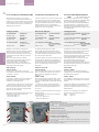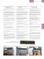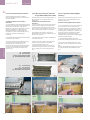
1
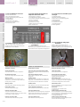
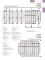
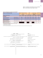
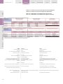
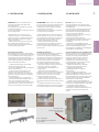
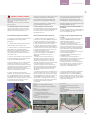
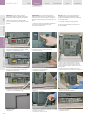
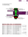
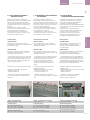
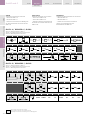
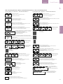
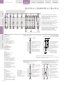
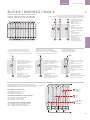
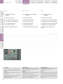
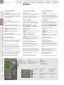
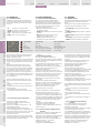
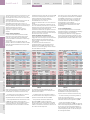
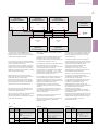
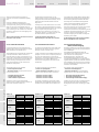
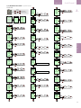
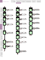
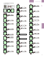
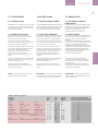
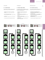
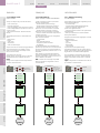
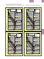
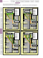
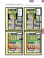
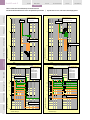
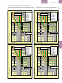
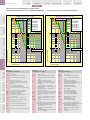
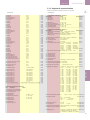
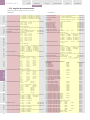
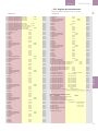
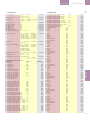
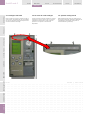
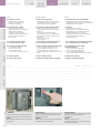
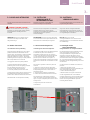
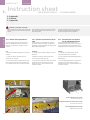
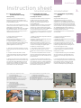
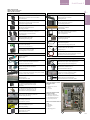
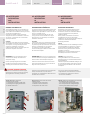
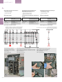
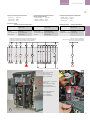
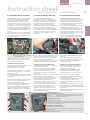
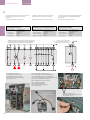
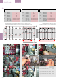
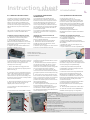
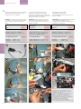
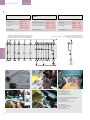
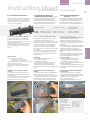
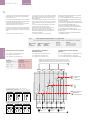
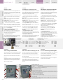
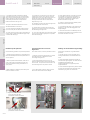
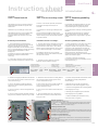
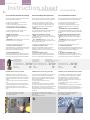
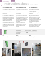
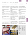
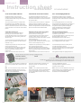
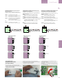
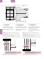
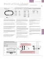
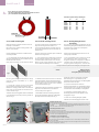
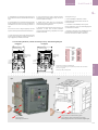
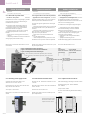
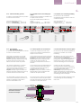
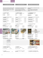
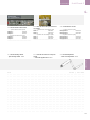
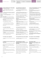
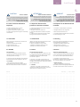
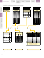
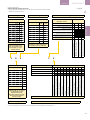
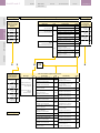
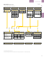
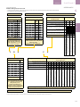
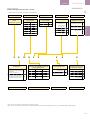
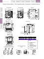
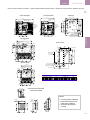
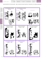
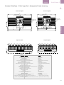
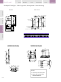
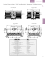
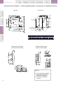
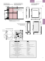
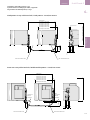
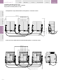
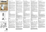
ACCESSORIES
Instruction sheet
Fiche d'instructions
EntelliGuard G
Introductieblad
4.3.4 Cassette Position Switch
4.3.4 Contacts d'indication de
position de la partie mobile (en option)
4.3.4 Cassette PositieIndicatie
contacten (optioneel)
A breaker in drawout mode has a cassette that is
used for mounting and connecting. The breaker , in
its moving portion mode, can be inserted into the
cassette and by use of the racking handle be
moved to one of four positions:
Les disjoncteurs débrochables ont une partie
fixe qui est utilisée pour le montage et le
raccordement. La partie mobile du disjoncteur
peut être insérée dans la partie fixe et adopter
quatre positions à l'aide de la manivelle de
Een schakelaar in uitrijdbare uitvoering heeft
een cassette die gebruikt wordt voor montage
en aansluiting. De vermogenschakelaar, als
bewegend deel, kan in de cassette geplaatst
worden en d.m.v. de montagehendel in een van
Catalogue number
| Numéros de catalogue
4.3
| Catalogusnummers
Montagekit of Reserve
Connected, Test, Disconnected or Withdrawn.
manœuvre: Inséré, Test, Débroché ou Extrait
To indicate in which position the EntelliGuard
Breaker is located within the Cassette position
Indication contacts are available for Connected,
Test and Disconnected position.
The disconnected position is only indicated when
minimum isolating distances between contacts on
both the main and auxiliary circuits have been
achieved.
Des contacts sont disponibles pour indiquer la
position dans la laquelle le disjoncteur
EntelliGuard se trouve: Inséré, Test ou Débroché.
La position Débroché n'est indiquée que lorsque
la distance d'isolation minimum est atteinte
entre les contacts sur les circuits principal et
auxiliaire. Ces dispositifs sont disponibles en
deux versions avec 1 ou 2 inverseurs d'indication
par position.
Ces contacts communément appelés contacts
de chariot, ils sont disponibles sous forme de
composants montés en usine ou d'appareils à
monter sur site.
Short description:
Two configurations are available:
--- 1 Changeover for each position.
--- 2 Changeovers for each position.
– The units come with 2 meters of supple wire each
coded by a ferule at it's ending.
– The device will indicate DISCONNECTED even
when the circuit breaker is fully withdrawn or
removed.
Description:
Deux configurations sont disponibles:
--- 1 inverseur par position.
--- 2 inverseurs par position.
- Les unités sont fournies avec 2 mètres de fil
souple codés par une férule à l'extrémité.
- L'appareil indiquera la position Débroché
même lorsque le disjoncteur sera complètement
extrait.
de drie posities geplaatst worden:
Connected, Test, Disconnected of Withdrawn.
Om aan te duiden in welke positie de
EntelliGuard schakelaar zich bevindt, zijn er
Indicatiecontacten verkrijgbaar voor de posities
Connected (Ingereden), Test en Disconnected
(Uitgereden).
De ontkoppelde positie wordt enkel aangegeven
indien er tussen twee contacten een minimum
isolatieafstand bestaat voor hoofd- en
hulpcircuits. De apparaten zijn beschikbaar in
twee paketten met 1 of 2 contacten per per
positie.
Algemeen genaamd Sledecontacten zijn deze
contacten beschikbaar als fabrieksgemonteerd
of ter plaatse monteerbaar onderdeel.
Korte omschrijving:
Er zijn twee configuraties beschikbaar:
--- 1 wisselcontact voor elke positie.
--- 2 wisselcontacten voor elke positie.
- De units worden geleverd met 2 meter soepele
draad met flensdoppen.
- Het toestel geeft UITGEREDEN weer zelfs indien
de vermogenschakelaar volledig uitgetrokken of
verwijderd is.
Installation of Cassette Position Indication
Contacts:
1. The moving portion of the draw out breaker
assembly should be safely isolated and removed
from the cassette.
2. Insert the Cassette Position Indication Contacts
wires from the opening from the inside of the
cassette and pull out as shown in Fig. B.
Installation des contacts d'indication de
position:
1. La partie mobile du disjoncteur débrochable
doit être isolée et extraite de la partie fixe,
comme indiqué dans la section 1 de ce manuel.
2. Insérer les câbles des contacts d'indication de
position depuis l'ouverture de l'intérieur de la
partie fixe et tirer comme indiqué sur la Fig. B.
Installatie van de Positieindicatiecontacten
van de Cassette:
1. Het bewegende deel van de uitrijdbare
uitvoeringschakelaar moet veilig geïsoleerd en
verwijderd zijn uit de cassette zoals omschreven
in hoofdstuk 1 van deze handleiding.
2. Voer de bedrading van de
Cassettepositieindicatiecontacten door de
A
C
B
D
CONTACTS
------------------------------------------------------------------------------------------------------------------| Unit met 3 contacten
GCPS1R
1NO/1NC per position | Unité avec 3 contacts
| Unit met 6 contacten
GCPS2R
2NO/2NC per position | Unité avec 6 contacts
E
Fig. A: Cassette Position Indic.
Contact parts
Fig. B: CPS wire insertion
Fig. C: CPS assembly
Fig. D: CPS assembly
Fig. E: CPS assembly
Fig. A: Éléments du contact
d'indication de position de la
partie fixe
Fig. B: Insertion des câbles du
CPS.
Fig. C: CPS
Fig. D: CPS
Fig. E: CPS
Afb. A: Cassette PositieIndic.
contactdelen
Afb. B: CPS draadinvoer
Afb. C: CPS montage
Afb. D: CPS montage
Afb. E: CPS montage
4.3-07