1
Connections Required for Correct Operation
• Coolant Sensor – 2 pin Connector
• Mass Air Flow (MAF) Sensor – 5 pin Connector
• Camshaft Position Sensor – 3 pin Connector
• Electronic Throttle Control – 6 pin Connector
• Manifold Absolute Pressure (MAP) Sensor – 3 pin Connector
• Oxygen Sensors (2 total) – 5 pin Connectors
• Knock Sensors (2 total) – 2 pin Connectors
• Ignition Coil Blocks (2 total) – 8 pin Connectors
• Fuel Injectors (8 total) – 2 pin Connectors
• Crankshaft Position Sensor – 3 pin Connector
• Accelerator Pedal Sensor – 6 pin Connector
• Ignition Switch Input (Wire) Wire
• Fuel Pump Control (Wire) Wire
• Engine Grounds (3 total) Eyelets
• Battery Power (Stud at Fuse/Relay Center)
Cooling Fan Control Wire
Attach a 12 volt ignition switch feed from the vehicle to the pink ignition
switch wire in the harness (this is required to enable the proper powerup sequence of the ECM). This can be routed into the passenger
compartment with the accelerator pedal connector and diagnostic
link connector. Next, connect battery power (minimum 8 gauge wire)
to the horizontal stud on the fuse relay center The other two studs are
for accessories and are 50 amp fused), and the harness installation is
complete.
Additional features and bulkhead connector descriptions are also
included below:
System Features
• The Fuse/Relay center contains all required fuses and relays for
proper engine operation. Spare fuse and relay openings are provided
for possible future customer use.
• The Fuse/Relay center includes a malfunction indicator light (MIL)
which will illuminate in the event of an engine fault code. See your
Chevrolet Performance Parts dealer to have this code retrieved at the
diagnostic link connector in the fuse/relay center (using a Tech2 with
Chevrolet Performance Parts Diagnostics selection or 2009 CTS LSA
Manual Trans Configuration). Codes can also be retrieved using an
aftermarket diagnostic scan tool capable of reading this configuration.
NOTE: The MIL will illuminate when the vehicle is keyed-up —this
is normal, and it will go out once the engine is started if there are
no current fault codes. A redundant MIL wire is included in the
wiring harness to allow a light to mounted inside the passenger
compartment. The wire is located in the wire bundle near the
pedal connector and the ignition voltage.
Optional Connections (Not required for operation)
• Alternator Control Connector
• Engine Oil Pressure Sensor – 3 pin Connector
• Vehicle Speed Sensor – 2 pin Connector Only required for CPP
Connect & Cruise Transmission Controls
• Optional User Outputs Bulkhead – 12 pin Connector (12-way)
Connections
Connect all engine/vehicle-side connectors before connecting the
harness to the ECM. All engine/vehicle-side connectors are functionally
labeled, consult a service manual if necessary to determine connection
locations (see following service manual information).
• A cooling fan is controlled by the ECM. Control is set to turn on a 12 V
fan at 97 Deg C (207 Deg F) coolant temperature. The fan control wire
is fused/relayed and must be connected directly to your fan.
• The fuel pump is controlled by the ECM. The control wire supplies
12 V and is fused/relayed and should connect to the 12 V side of the
fuel pump.
NOTE: It may be easier to install the harness on the engine before
installing the engine into the vehicle.
The harness includes a fuse/relay center containing all required fuses
and relays, and also a 12-way bulkhead connector (with sealed mating
connector) which contains outputs that may be useful to the user (see
‘Bulkhead Connector Outputs’ section below). The fuse/relay center
should be mounted as high in the engine compartment as possible to
avoid unnecessary splash and road debris. Likewise, keep the 12-way
bulkhead connector and diagnostic link connector (both connect from
the fuse/relay center) as high and protected as possible.
The 3 ECM connectors are indexed to connect only in the correct
locations. Install by pressing down firmly until the connector is seated,
then pull the top slider bar down until it snaps and locks into place. The
bar should slide easily and will not move unless the connector is seated
properly, do not use excessive force.
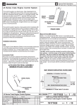
• A tachometer signal is included in the bulkhead connector (see
below). This is a 2 pulse/rev output which may correspond to
a 4-cylinder setup in some tachometers or transmission controllers.
Note the signal is a low voltage square wave, some tachometers or
transmission controllers may need a pull-up resistor in order to read
the signal, similar to a 5000 ohm, ¼ watt resistor– this detail is left to
the user. The following circuit has worked for numerous devices – the
resister value may need to be changed if your device does not read
this output properly.
Bulkhead Connector Pin C
Engine Speed – Tach Out
Pull High Tach Out
Attach the harness ground eyelets (3 total) to the engine block, ensuring
5000Ω
the connections are clean and secure, and attach the fuel pump wire
Bulkhead Connector Pin L
from the fuse/relay center to the power side of the pump (this feed is
Ignition Voltage
fused and relay-controlled from the ECM).
NOTE: When connected to the CP Supermatic Connect and Cruise
Make sure all intended engine and vehicle side connections have
Harness the pull up resister is not required for the Transmission
been made before proceeding to connect power.
Controller.
Main Battery
Auxiliary Devices 50 amp fused
• An oil pressure output is included in the bulkhead connector and can
Connection
be used for a pressure gauge if desired (see below for scaling). If you
are using the optional oil pressure signal in the bulk head connector,
ensure the harness is plugged into oil pressure sensor .
• A vehicle speed output is included in the bulkhead connector for use
with auto-scaling speedometers. The vehicle speed sensor connector
in the harness must be attached to a variable reluctance type speed
sensor (typical of most late model GM automatic transmissions) for
this to function.
TITLE
LS Series Crate Engine Control System
REV 28JN12
ALL INFORMATION WITHIN ABOVE BORDER TO BE PRINTED EXACTLY AS SHOWN ON 8 1/2 x 11
WHITE 16 POUND BOND PAPER. PRINT ON BOTH SIDES, EXCLUDING TEMPLATES.
TO BE UNITIZED IN ACCORDANCE WITH GM SPECIFICATIONS.
DATE
PART NO.
19171935
REVISION
SHEET
3
OF
23
AUTH