1
ML6300
Technical reference guide
ML6300FB
PREFACE
Every effort has been made to ensure that the information in this document is
complete, accurate, and up-to-date. Oki Printing Solutions assumes no
responsibility for the results of errors beyond its control. Oki Printing Solutions also
cannot guarantee that changes in software and equipment made by other
manufacturers and referred to in this guide will not affect the applicability of the
information in it. Mention of software products manufactured by other companies
does not necessarily constitute endorsement by Oki Printing Solutions.
While all reasonable efforts have been made to make this document as accurate and
helpful as possible, we make no warranty of any kind, expressed or implied, as to
the accuracy or completeness of the information contained herein.
The most up-to-date drivers and manuals are available from the Oki Printing
Solutions web site:
http://www.okiprintingsolutions.com
Copyright © 2006 Oki Printing Solutions.
Oki, OKI Printing Solutions and Microline are registered trademarks of Oki Electric
Industry Company, Ltd.
ENERGY STAR is a trademark of the United States Environmental Protection Agency.
Microsoft, MS-DOS and Windows are registered trademarks of Microsoft
Corporation.
Other product names and brand names are registered trademarks or trademarks of
their proprietors.
As an ENERGY STAR Program Participant, the manufacturer has
determined that this product meets the ENERGY STAR guidelines
for energy efficiency.
This product complies with the requirements of the Council
Directives 89/336/EEC (EMC) and 73/23/EEC (LVD) as amended
where applicable on the approximation of the laws of the member
states relating to electromagnetic compatibility and low voltage.
Preface > 2
CONTENTS
Preface . . . . . . . . . . . . . . . . . . . . . . . . . . . . . . . . . . 2
Notes, cautions and warnings . . . . . . . . . . . . . . . 10
Introduction . . . . . . . . . . . . . . . . . . . . . . . . . .
Features . . . . . . . . . . . . . . . . . . . . . . . . . . .
Standard configuration . . . . . . . . . . . . . . . . .
Identifying component parts . . . . . . . . . . . . .
Front view. . . . . . . . . . . . . . . . . . . . . . . .
Rear view . . . . . . . . . . . . . . . . . . . . . . . .
.
.
.
.
.
.
.
.
.
.
.
.
.
.
.
.
.
.
11
11
12
12
13
14
About this guide . . . . . . . . . . . . . . . . . . . . . . . . . . 15
Online usage . . . . . . . . . . . . . . . . . . . . . . . . . . . 16
Printing pages . . . . . . . . . . . . . . . . . . . . . . . . . . 16
Interface specifications . . . . . . . . . . . . . . . . . . .
IEEE1284 parallel interface specifications . . . . . .
Connectors and cable . . . . . . . . . . . . . . . . . .
Parallel interface signals . . . . . . . . . . . . . . . .
Parallel interface levels . . . . . . . . . . . . . . . . .
Parallel interface circuits . . . . . . . . . . . . . . . .
Parallel interface timing chart . . . . . . . . . . . .
Support mode . . . . . . . . . . . . . . . . . . . . . . .
Universal Serial Bus (USB) . . . . . . . . . . . . . . . .
Connectors . . . . . . . . . . . . . . . . . . . . . . . . .
Cable . . . . . . . . . . . . . . . . . . . . . . . . . . . . .
USB interface signals . . . . . . . . . . . . . . . . . .
Mode and class of device . . . . . . . . . . . . . . .
Data signalling rate . . . . . . . . . . . . . . . . . . .
Interface circuit . . . . . . . . . . . . . . . . . . . . . .
Signal level . . . . . . . . . . . . . . . . . . . . . . . . .
Timing chart . . . . . . . . . . . . . . . . . . . . . . . .
Option interface specifications . . . . . . . . . . . . . .
Interface signals . . . . . . . . . . . . . . . . . . . . .
Electrical characteristics . . . . . . . . . . . . . . . .
Interface timing charts . . . . . . . . . . . . . . . . .
Receiving margin . . . . . . . . . . . . . . . . . . . . .
Description of communication procedures . . . .
Interface control code . . . . . . . . . . . . . . . . .
Local test function . . . . . . . . . . . . . . . . . . . .
.
.
.
.
.
.
.
.
.
.
.
.
.
.
.
.
.
.
.
.
.
.
.
.
.
18
18
18
19
19
20
20
20
21
21
21
21
22
22
22
22
24
25
25
26
28
28
28
29
30
Operator interface . . . . . . . . . . . . . . . . . . . . . . .
Operator panel functions . . . . . . . . . . . . . . . . . .
Print mode . . . . . . . . . . . . . . . . . . . . . . . . .
Hex Dump mode, Menu mode, Test mode. . . .
.
.
.
.
32
32
32
35
Preface > 3
Maintenance mode 1 . . . . . . . .
Maintenance mode 2 . . . . . . . .
Lamp functions . . . . . . . . . . . . . .
Alarm/error indications . . . . . . . . .
Recoverable alarms . . . . . . . . .
Unrecoverable alarms. . . . . . . .
Menu selection . . . . . . . . . . . . . . .
Overview . . . . . . . . . . . . . . . .
Button switch functions . . . . . .
Operation . . . . . . . . . . . . . . . .
Menu items . . . . . . . . . . . . . . .
Registration menu . . . . . . . . . . . .
Overview . . . . . . . . . . . . . . . .
Operation . . . . . . . . . . . . . . . .
Registration details . . . . . . . . .
Self test printing . . . . . . . . . . . . .
Rolling ASCII self test printing . . . .
Hexadecimal Dump mode . . . . . . .
Overview . . . . . . . . . . . . . . . .
Operation . . . . . . . . . . . . . . . .
Function . . . . . . . . . . . . . . . . .
Continuous paper auto-loading . . .
Continuous paper auto-parking . . .
Cut-sheet paper semi-auto-loading
Form tear-off . . . . . . . . . . . . . . . .
Function . . . . . . . . . . . . . . . . .
Set-up . . . . . . . . . . . . . . . . . .
Action. . . . . . . . . . . . . . . . . . .
.
.
.
.
.
.
.
.
.
.
.
.
.
.
.
.
.
.
.
.
.
.
.
.
.
.
.
.
.
.
.
.
.
.
.
.
.
.
.
.
.
.
.
.
.
.
.
.
.
.
.
.
.
.
.
.
36
36
37
37
37
38
39
39
40
40
41
54
54
54
55
55
56
57
57
57
58
58
58
59
59
59
59
60
Command descriptions . . . . . . . . . . . . . . . . . . . .
Horizontal control. . . . . . . . . . . . . . . . . . . . . . .
Carriage return . . . . . . . . . . . . . . . . . . . . . .
Horizontal tab set . . . . . . . . . . . . . . . . . . . .
Horizontal tab . . . . . . . . . . . . . . . . . . . . . . .
Reset tab settings to power-on default values .
Execute absolute horizontal dot position . . . . .
Execute relative dot position . . . . . . . . . . . . .
Move right relative dot position . . . . . . . . . . .
Move left relative dot position . . . . . . . . . . . .
Left margin set . . . . . . . . . . . . . . . . . . . . . .
Right margin set . . . . . . . . . . . . . . . . . . . . .
Set left/right margin . . . . . . . . . . . . . . . . . .
Auto justification . . . . . . . . . . . . . . . . . . . . .
Set/reset unidirection printing . . . . . . . . . . . .
.
.
.
.
.
.
.
.
.
.
.
.
.
.
.
61
61
61
61
63
63
64
64
66
67
67
68
69
70
71
Preface > 4
.
.
.
.
.
.
.
.
.
.
.
.
.
.
.
.
.
.
.
.
.
.
.
.
.
.
.
.
.
.
.
.
.
.
.
.
.
.
.
.
.
.
.
.
.
.
.
.
.
.
.
.
.
.
.
.
.
.
.
.
.
.
.
.
.
.
.
.
.
.
.
.
.
.
.
.
.
.
.
.
.
.
.
.
.
.
.
.
.
.
.
.
.
.
.
.
.
.
.
.
.
.
.
.
.
.
.
.
.
.
.
.
.
.
.
.
.
.
.
.
.
.
.
.
.
.
.
.
.
.
.
.
.
.
.
.
.
.
.
.
.
.
.
.
.
.
.
.
.
.
.
.
.
.
.
.
.
.
.
.
.
.
.
.
.
.
.
.
.
.
.
.
.
.
.
.
.
.
.
.
.
.
.
.
.
.
.
.
.
.
.
.
.
.
.
.
.
.
.
.
.
.
.
.
.
.
.
.
.
.
.
.
.
.
.
.
.
.
.
.
.
.
.
.
.
.
.
.
.
.
.
.
.
.
.
.
.
.
.
.
.
.
.
.
.
.
.
.
.
.
.
.
One line unidirectional printing . .
Set/reset half speed printing . . . .
Backspace. . . . . . . . . . . . . . . . .
One character data delete. . . . . .
Vertical control . . . . . . . . . . . . . . .
Set 1/8 inch fixed line spacing. . .
Set 7/72 inch fixed line spacing . .
Start line spacing. . . . . . . . . . . .
Set 1/6 inch line spacing. . . . . . .
Set n/60 inch line spacing. . . . . .
Set n/180 inch line spacing . . . . .
Set n/360 inch fine line spacing . .
Set n/360 inch line spacing . . . . .
Line feed . . . . . . . . . . . . . . . . .
Set/reset automatic linefeed . . . .
Fine line feed (n/180 inch) . . . . .
Fine line feed (n/360 inch) . . . . .
Fine line feed (n/360 inch) . . . . .
Reverse line feed . . . . . . . . . . . .
Reverse line feed . . . . . . . . . . . .
Form feed . . . . . . . . . . . . . . . . .
Vertical tab . . . . . . . . . . . . . . . .
Set vertical tab stops . . . . . . . . .
Set vertical format unit (VFU) . . .
Select vertical tab channel . . . . .
Form length set by inches . . . . . .
Form length set by lines . . . . . . .
Set perforation auto skip . . . . . .
Reset perforation auto skip . . . . .
Top of form set . . . . . . . . . . . . .
Set vertical units . . . . . . . . . . . .
Set n/360 inch fine line spacing . .
Set n/360 inch line spacing . . . . .
Set forward line spacing . . . . . . .
Set reverse line spacing . . . . . . .
Character set. . . . . . . . . . . . . . . . .
Copies ROM CG to RAM CG . . . . .
Character definition . . . . . . . . . .
Load DLL character . . . . . . . . . .
DLL font select . . . . . . . . . . . . .
Foreign character set select . . . .
Select international character set.
Select character table. . . . . . . . .
Preface > 5
.
.
.
.
.
.
.
.
.
.
.
.
.
.
.
.
.
.
.
.
.
.
.
.
.
.
.
.
.
.
.
.
.
.
.
.
.
.
.
.
.
.
.
.
.
.
.
.
.
.
.
.
.
.
.
.
.
.
.
.
.
.
.
.
.
.
.
.
.
.
.
.
.
.
.
.
.
.
.
.
.
.
.
.
.
.
.
.
.
.
.
.
.
.
.
.
.
.
.
.
.
.
.
.
.
.
.
.
.
.
.
.
.
.
.
.
.
.
.
.
.
.
.
.
.
.
.
.
.
.
.
.
.
.
.
.
.
.
.
.
.
.
.
.
.
.
.
.
.
.
.
.
.
.
.
.
.
.
.
.
.
.
.
.
.
.
.
.
.
.
.
.
.
.
.
.
.
.
.
.
.
.
.
.
.
.
.
.
.
.
.
.
.
.
.
.
.
.
.
.
.
.
.
.
.
.
.
.
.
.
.
.
.
.
.
.
.
.
.
.
.
.
.
.
.
.
.
.
.
.
.
.
.
.
.
.
.
.
.
.
.
.
.
.
.
.
.
.
.
.
.
.
.
.
.
.
.
.
.
.
.
.
.
.
.
.
.
.
.
.
.
.
.
.
.
.
.
.
.
.
.
.
.
.
.
.
.
.
.
.
.
.
.
.
.
.
.
.
.
.
.
.
.
.
.
.
.
.
.
.
.
.
.
.
.
.
.
.
.
.
.
.
.
.
.
.
.
.
.
.
.
.
.
.
.
.
.
.
.
.
.
.
.
.
.
.
.
.
.
.
.
.
.
.
.
.
.
.
.
.
.
.
.
.
.
.
.
.
.
.
.
.
.
.
.
.
.
.
.
.
.
.
.
.
.
.
.
.
.
.
.
.
.
.
.
.
.
.
.
.
.
.
.
.
.
.
.
.
.
.
.
.
.
.
.
.
.
.
.
.
.
.
.
.
.
.
.
.
.
.
72
72
73
74
74
74
75
75
75
76
77
77
78
78
79
79
80
81
81
82
83
83
84
85
86
86
87
88
88
89
89
89
90
91
91
91
91
92
94
96
96
99
99
Enable upper ASCII characters . . . . . . . . . . .
Select character set II . . . . . . . . . . . . . . . . .
Print continuously from all characters chart. . .
Print one character from all characters chart . .
Select character set I . . . . . . . . . . . . . . . . . .
Select character set II . . . . . . . . . . . . . . . . .
Code page select . . . . . . . . . . . . . . . . . . . . .
Assign character table . . . . . . . . . . . . . . . . .
Select character table. . . . . . . . . . . . . . . . . .
Select font . . . . . . . . . . . . . . . . . . . . . . . . .
Print quality – select HSD . . . . . . . . . . . . . . .
Print quality – select HSD . . . . . . . . . . . . . . .
Font description . . . . . . . . . . . . . . . . . . . . . . . .
Select character font . . . . . . . . . . . . . . . . . .
Select type styles . . . . . . . . . . . . . . . . . . . .
Set/reset proportional spacing. . . . . . . . . . . .
Set/reset proportional spacing. . . . . . . . . . . .
Set pica character pitch (10 CPI) . . . . . . . . . .
Set 10 CPI . . . . . . . . . . . . . . . . . . . . . . . . .
Set elite character pitch (12 CPI) . . . . . . . . . .
Set 12 CPI . . . . . . . . . . . . . . . . . . . . . . . . .
Set 15 character per inch . . . . . . . . . . . . . . .
Set compressed character pitch (17.1/20 CPI)
Set compressed character pitch (17.1/20 CPI)
Reset compressed character pitch . . . . . . . . .
Set character spacing . . . . . . . . . . . . . . . . . .
Set italic characters . . . . . . . . . . . . . . . . . . .
Reset italic characters . . . . . . . . . . . . . . . . .
Set italic character . . . . . . . . . . . . . . . . . . . .
Reset italic characters . . . . . . . . . . . . . . . . .
Text print features . . . . . . . . . . . . . . . . . . . . . .
Set/reset underlining . . . . . . . . . . . . . . . . . .
Set subscript/superscript . . . . . . . . . . . . . . .
Reset super/subscript. . . . . . . . . . . . . . . . . .
Set emphasised print mode. . . . . . . . . . . . . .
Reset emphasised print mode . . . . . . . . . . . .
Set double strike print mode . . . . . . . . . . . . .
Reset double strike mode . . . . . . . . . . . . . . .
Set double or expanded characters . . . . . . . .
Set immediate double width characters . . . . .
Set immediate double width characters . . . . .
Reset immediate double width characters . . . .
Set/reset double height characters . . . . . . . .
Preface > 6
.100
.100
.101
.101
.101
.102
.102
.105
.106
.106
.107
.108
.108
.108
.109
.110
.111
.112
.112
.112
.113
.113
.114
.114
.115
.115
.116
.116
.116
.117
.117
.117
.118
.119
.119
.119
.120
.120
.120
.121
.122
.122
.122
Set/reset double height characters . . . .
Set/reset double height characters . . . .
Overscore set/reset . . . . . . . . . . . . . . .
Select character style . . . . . . . . . . . . . .
Set double width or expanded characters
Set/reset double height characters . . . .
Graphics mode. . . . . . . . . . . . . . . . . . . . .
Enter/exit bit image graphics . . . . . . . .
Single density graphics. . . . . . . . . . . . .
Double density graphics . . . . . . . . . . . .
Quasi-double-density graphics. . . . . . . .
Set quadruple density graphics . . . . . . .
Reassign alternate graphics codes . . . . .
Graphics resolution . . . . . . . . . . . . . . .
Select aspect ratio . . . . . . . . . . . . . . . .
Composite commands. . . . . . . . . . . . . . . .
Print mode select . . . . . . . . . . . . . . . . .
Print mode select . . . . . . . . . . . . . . . . .
General control . . . . . . . . . . . . . . . . . . . .
Printer initialisation . . . . . . . . . . . . . . .
Cancel code . . . . . . . . . . . . . . . . . . . .
Set bit 7 code to 1 . . . . . . . . . . . . . . . .
Set bit 7 code to 0 . . . . . . . . . . . . . . . .
Reset 8 bit mode . . . . . . . . . . . . . . . . .
Set print suppress . . . . . . . . . . . . . . . .
Print suppress . . . . . . . . . . . . . . . . . . .
Reset print suppress mode . . . . . . . . . .
Stop printing . . . . . . . . . . . . . . . . . . . .
Enable paper out sensor . . . . . . . . . . . .
Disable paper out sensor . . . . . . . . . . .
Select emulation . . . . . . . . . . . . . . . . .
Printer initialisation . . . . . . . . . . . . . . .
Printer initialisation . . . . . . . . . . . . . . .
Barcode . . . . . . . . . . . . . . . . . . . . . . . . .
Print barcode. . . . . . . . . . . . . . . . . . . .
.
.
.
.
.
.
.
.
.
.
.
.
.
.
.
.
.
.
.
.
.
.
.
.
.
.
.
.
.
.
.
.
.
.
.
.123
.124
.124
.125
.125
.126
.127
.127
.130
.130
.131
.132
.133
.134
.135
.136
.136
.137
.137
.137
.138
.138
.138
.139
.139
.139
.140
.140
.140
.141
.142
.142
.143
.143
.143
Specifications . . . . . . . . . . . . . . . . . . . . . . . . . . .
Physical specification . . . . . . . . . . . . . . . . . . . .
Power requirements . . . . . . . . . . . . . . . . . . . . .
Electrical insulation. . . . . . . . . . . . . . . . . . . . . .
Environmental conditions . . . . . . . . . . . . . . . . .
Noise . . . . . . . . . . . . . . . . . . . . . . . . . . . . . . .
Agency approvals . . . . . . . . . . . . . . . . . . . . . . .
Print specification . . . . . . . . . . . . . . . . . . . . . . .
147
.147
.147
.148
.148
.149
.149
.149
Preface > 7
.
.
.
.
.
.
.
.
.
.
.
.
.
.
.
.
.
.
.
.
.
.
.
.
.
.
.
.
.
.
.
.
.
.
.
.
.
.
.
.
.
.
.
.
.
.
.
.
.
.
.
.
.
.
.
.
.
.
.
.
.
.
.
.
.
.
.
.
.
.
.
.
.
.
.
.
.
.
.
.
.
.
.
.
.
.
.
.
.
.
.
.
.
.
.
.
.
.
.
.
.
.
.
.
.
Paper specification . . . . . . . . . . . . . . . . . . . . . . .152
Ribbon specification . . . . . . . . . . . . . . . . . . . . . .152
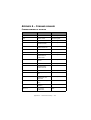
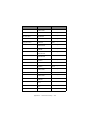
Appendix A – Command summary . . . . . . . . . . . 153
Command summary by initiator . . . . . . . . . . . . . .153
Command summary by function. . . . . . . . . . . . . .161
Appendix B – Print modes/features . . . . . . . . . . 168
IBM mode . . . . . . . . . . . . . . . . . . . . . . . . . . . . .168
EPSON mode . . . . . . . . . . . . . . . . . . . . . . . . . . .169
Appendix C – Code pages . . . . . . . . . . . . . . . . . . 170
Appendix D – Media specifications . . . . . . . . . . .
General. . . . . . . . . . . . . . . . . . . . . . . . . . . . . .
Unsuitable paper . . . . . . . . . . . . . . . . . . . . .
Pre-printed paper . . . . . . . . . . . . . . . . . . . .
Paper storage conditions. . . . . . . . . . . . . . . .
Usable paper types and assurance range . . . .
Continuous paper (continuous forms) . . . . . . . . .
Vertical and horizontal dimensions . . . . . . . . .
Feed hole (sprocket hole) positions and sizes .
Perforation dimensions . . . . . . . . . . . . . . . . .
Paper size and printing areas . . . . . . . . . . . .
Paper quality . . . . . . . . . . . . . . . . . . . . . . . .
Paper weight and max. no. of form parts . . . .
Methods for joining parts of multipart forms . .
Horizontal perforation rising . . . . . . . . . . . . .
Misalignment between feed holes . . . . . . . . .
Binding holes . . . . . . . . . . . . . . . . . . . . . . .
Corner cuts . . . . . . . . . . . . . . . . . . . . . . . . .
Paper condition . . . . . . . . . . . . . . . . . . . . . .
Cut-sheet paper . . . . . . . . . . . . . . . . . . . . . . . .
Vertical and horizontal dimensions . . . . . . . . .
Paper size and printing areas . . . . . . . . . . . .
Paper quality . . . . . . . . . . . . . . . . . . . . . . . .
Paper weight and max. no. of form parts . . . .
Joining of parts of multipart forms . . . . . . . . .
Binding holes . . . . . . . . . . . . . . . . . . . . . . .
Perforations . . . . . . . . . . . . . . . . . . . . . . . .
Folds, bends and curls of cut-sheet paper . . . .
Envelopes (individual). . . . . . . . . . . . . . . . . . . .
Label paper . . . . . . . . . . . . . . . . . . . . . . . . . . .
Package delivery slips . . . . . . . . . . . . . . . . . . . .
Recycled paper . . . . . . . . . . . . . . . . . . . . . . . .
178
.178
.178
.179
.180
.180
.181
.181
.182
.184
.186
.187
.188
.188
.192
.193
.193
.194
.195
.196
.196
.197
.199
.199
.200
.201
.202
.203
.204
.205
.209
.210
Index . . . . . . . . . . . . . . . . . . . . . . . . . . . . . . . . . 211
Preface > 8
Oki Printing Solutions contact details . . . . . . . . 212
Preface > 9
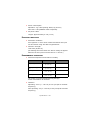
NOTES, CAUTIONS AND WARNINGS
NOTE
A note provides additional information to supplement the main
text.
CAUTION!
A caution provides additional information which, if
ignored, may result in equipment malfunction or
damage.
WARNING!
A warning provides additional information which, if
ignored, may result in a risk of personal injury.
Notes, cautions and warnings > 10
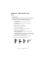
INTRODUCTION
The ML6300FB is designed to provide highly reliable letter quality
printing and high resolution graphics for the desktop/office
printing environment. It combines state-of-the-art, 24-pin, serial
impact dot matrix printing technology with advanced materials
and superior construction to provide high performance and
versatility in a desktop sized unit. Careful attention to
ergonomics and application needs provides user friendly
operation for operators of varying technical capabilities.
FEATURES
ML6300FB features include:
> OKI smart Paper Handling
> Direct access control panel
> Structured direct access menu for easy set up
> Printhead life: 200M characters (average) in 10 CPI Utility
mode at normal 25% duty, 35% page density
> Bidirectional short-line-seeking printing
> Print speed:
400 CPS HSD (10 CPI)
300 CPS Utility (10 CPI)
100 CPS LQ (10 CPI)
> Paper feed
Rear path (with push tractor)
Front tray
> Paper handling
Automatic sheet loading
Short paper tear-off available by menu selection or TEAR
switch operation
Auto-loading for continuous paper
Auto park feature
> Paper copies: 9 – 11 lb, 5 part
> Cartridge ribbon
> Interfaces
Introduction > 11
Standard IEEE1284 parallel interface
USB interface.
> 58 dBA noise
> 64 kbytes max. receive buffer
> Line feed resolution at 1/6 in, 1/8 in, n/60 in, n/72 in,
n/180 in, n/216 in, n/360 in
> Agency approved by:
200 V system: GE BSI
> Barcode data printing
> Postnet bar code data printing
> EMI approved 200 V system: EN55022 Class B
STANDARD CONFIGURATION
The ML6300FB consists of the following components:
> Printer mechanism
> Power supply unit
> Control board (including an IEEE1284 parallel interface)
> Acoustic covers
> Push tractor feed unit
> Option
•
RS-232C Serial Interface Board
•
OL7120e 100BASE-TX/10BASE-T Network Board
NOTE
It is not recommended that you use either the parallel or USB
port when the RS-232C or OL7120e option is installed in this
product.
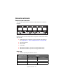
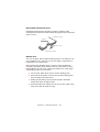
IDENTIFYING COMPONENT PARTS
The main parts of your printer are identified and briefly explained
below.
Introduction > 12
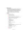
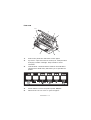
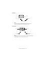
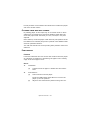
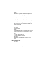
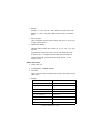
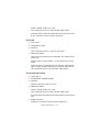
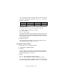
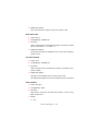
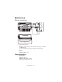
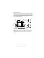
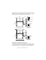
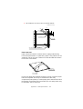
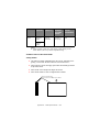
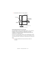
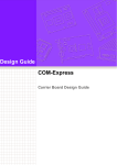
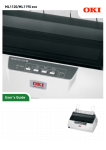
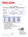
FRONT VIEW
10
1
2
3
9
8
7
4
6
5
1.
Print Head: prints the characters on the paper.
2.
Top Cover: open and close for access, for example when
changing a ribbon cartridge. Keep closed for noise
reduction.
3.
Control Panel: contains button switches and indicators
(described in detail later) that allow you to operate the
printer.
4.
Power Switch: to turn the printer power ON/OFF.
5.
Platen Knob: turn to move or eject the paper.
Introduction > 13
6.
Paper Tray: to hold cut sheet paper for use by the printer
(one sheet at a time).
7.
Paper Guide: can be adjusted as required to locate the left
edge of cut sheet paper.
8.
Paper Type Lever: set according to the type of paper used
– cut sheet or continuous forms.
9.
Paper Thickness Lever: set according to the thickness of
the paper. There is also a setting to facilitate ribbon
replacement.
10.
Ribbon Cartridge: holds the printer ribbon.
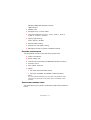
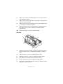
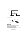
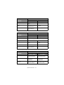
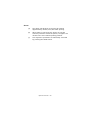
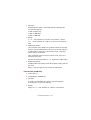
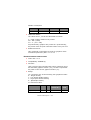
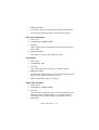
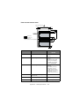
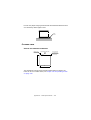
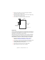
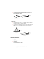
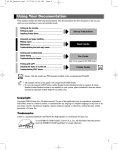
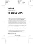
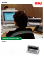
REAR VIEW
1
2
6
3
5
4
1.
Optional connector position: connect to optional accessory
serial interface card or 100BASE-TX/10BASE-T network
card.
2.
USB connector: connect to USB interface cable.
3.
Parallel connector: connect to parallel interface cable.
4.
Pin Tractor: to load and feed continuous forms.
5.
Power connector: connect to printer power cable.
6.
Rear Cover: open and close for access, for example when
loading continuous forms.
Introduction > 14
ABOUT THIS GUIDE
NOTE
Images used in this manual may include optional features that
your printer does not have installed.
If required, you may wish to refer for basic information to the
User’s Guide which is stored on the manuals CD.
This manual is your Technical Reference guide (check the web
site, www.okiprintingsolutions.com, for the most up-to-date
version) for your printer and forms part of the overall user
support listed below:
> Installation Safety booklet: provides information as to
safe use of the printer.
This is a paper document that is packaged with the printer
and should be read before setting up your printer.
> Set-up guide: to describe how to unpack and set up your
printer.
This is a paper document that is packaged with the printer.
> This Technical Reference Guide: to provide detailed
technical information for programmers and more technical
users.
This is an electronic document available on the web site
www.okieng.com.
> User’s Guide: to help you to become familiar with your
printer and make the best use of its many features. Also
included are guidelines for troubleshooting and
maintenance to ensure that it performs at its best.
Additionally, information is provided for adding optional
accessories as your printing needs evolve.
This is an electronic document stored on the manuals CD.
> Network Configuration Guide: to provide detailed
technical information for network administrators to
configure the optional accessory network interface.
This is an electronic document stored on the CD that
accompanies the network interface card optional
accessory.
About this guide > 15
> Installation Guides: accompany consumable items and
optional accessories to describe how to install them.
These are paper documents that are packaged with the
consumables and optional accessories.
> Online Help: online information accessible from the
printer driver and utility software.
ONLINE USAGE
This guide is intended to be read on screen using an Adobe
Acrobat Reader. Use the navigation and viewing tools provided in
Acrobat.
You can access specific information in two ways:
> In the list of bookmarks down the left hand side of your
screen, click on the topic of interest to jump to the
required topic. (If the bookmarks are not available, use
the “Contents” on page 3.)
> In the list of bookmarks, click on Index to jump to the
Index. (If the bookmarks are not available, use the
“Contents” on page 3.) Find the term of interest in the
alphabetically arranged index and click on the associated
page number to jump to the page containing the term.
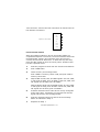
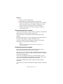
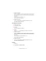
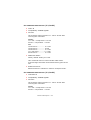
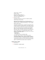
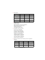
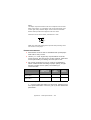
PRINTING PAGES
The whole manual, individual pages, or sections may be printed.
The procedure is:
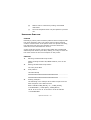
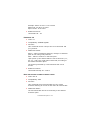
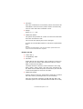
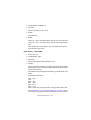
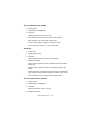
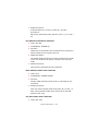
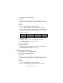
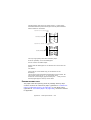
1.
From the toolbar, select [File], then [Print] (or press the
Ctrl + P keys).
About this guide > 16
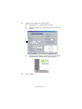
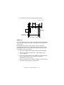
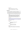
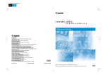
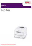
2.
Choose which pages you wish to print:
(a)
[All pages], (1), for the entire manual.
(b)
[Current page], (2), for the page at which you are
looking.
1
2
3
(c)
3.
[Pages from] and [to], (3), for the range of pages
you specify by entering their page numbers.
Click on [OK].
About this guide > 17
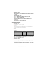
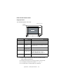
INTERFACE SPECIFICATIONS
IEEE1284 PARALLEL INTERFACE SPECIFICATIONS
CONNECTORS AND CABLE
Connectors
Printer side:
36-pin receptacle 57-40360 (Amphenol or Daiichi
Electronics) or equivalent
Cable side:
36-pin plug 57-30360 (Amphenol or Daiichi Electronics) or
equivalent, or plug 552274-1 (Amphenol) and cover
552073-1 (Amphenol) or equivalent
Cable
Use a cable less than 6 ft (1.8 m) in total length.
(A shielded cable is required and use of twisted-pair wires
is recommended for noise prevention.)
The cable is not supplied with the printer.
Interface specifications > 18
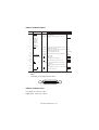
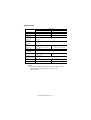
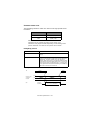
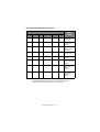
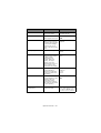
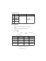
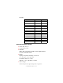
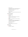
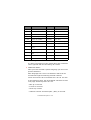
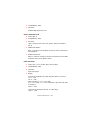
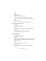
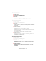
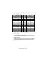
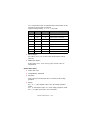
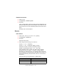
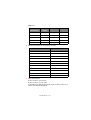
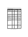
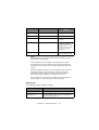
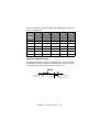
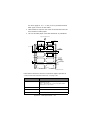
PARALLEL INTERFACE SIGNALS
Description
PinNo.
Direction
Signal
Compatible
Nibble
1
STROBE
To printer
Samples input data when changing from low
level to high level.
2
DATA BIT 1
To printer
3
DATA BIT 2
Input data: High level indicates 1 and low
level 0 .
4
DATA BIT 3
5
DATA BIT 4
6
DATA BIT 5
7
DATA BIT 6
8
DATA BIT 7
9
DATA BIT 8
10
ACKNLG
From printer Indicates character input completion, or function PrtClk
operation end, at low level.
11
BUSY
From printer Indicates data cannot be received at high level. PrtBusy
Data can be input at low level.
12
PE
From printer High level indicates paper end.
AckDataReq
13
SEL
From printer High level indicates select (on line) condition.
Xflag
14
AUTO FEEDXT
16, 33
To printer
17
CHASSIS GROUND
18
+5 V
Frame ground.
From printer +5 V supply (17 mA maximum)
Twisted pair return (for pin No. 1 to 12)
19 to 30 GND
INIT
32
ERROR
To printer
From printer This signal goes from high to low level when
paper runs out.
(Possible to indicate error and Off Line state).
nDataAvail
Unused
15, 34
Fixed to High (Connected to +5 V via 3.3 K Ω)
35
36
HostBusy
Signal ground.
GND
31
HostClk
SLCT IN
To printer
Connected to input port
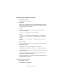
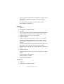
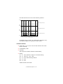
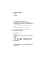
NOTE
Connector pin arrangement for above.
18
1
36
19
PARALLEL INTERFACE LEVELS
Low level: 0.0 V to + 0.8 V
High level: +2.3 V to +5.0 V
Interface specifications > 19
IEEE1284
active
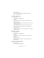
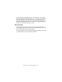
PARALLEL INTERFACE CIRCUITS
(a)
Receiver
(b)
Driver
1
2
BUSY, ACKNOWLEDGE, PAPER END, SLECT, FAULT
LVC161284
HL
240 Ω
+5 V
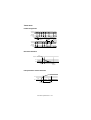
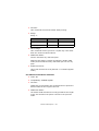
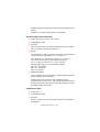
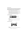
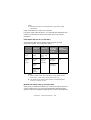
PARALLEL INTERFACE TIMING CHART
DATA BIT1 to
DATA BIT8
STROBE
DATA
(H)
(L)
(H)
BUSY
0.5 µs
min
0.5 µs
min
0.5 µs
min
(L)
1.0 µs
max
ACKNLG
(H)
(L)
2.5 µs(TYP)
SUPPORT MODE
Compatible
Nibble (PnP Device ID only)
Interface specifications > 20
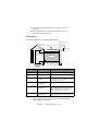
UNIVERSAL SERIAL BUS (USB)
Universal Serial Bus Specification Revision 2.0 compliance.
CONNECTORS
Printer Side:
“B” Receptacle (Upstream Input to the USB Device)
Cable Side:
Series “B” Plug
CABLE
Length:
Max. 5 m (Cable must be shielded and meet the USB Spec
Rev 2.0 for normal operation.)
The cable is not supplied with the printer.
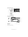
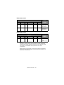
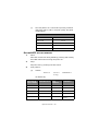
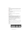
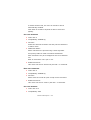
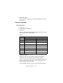
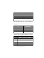
USB INTERFACE SIGNALS
CONTACT NUMBER
SIGNAL NAME
1
Vbus (Not Used)
2
D-
3
D+
4
GND
Shell
Shield
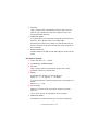
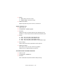
NOTE
Connector pin arrangement for above:
2
1
3
4
Interface specifications > 21
MODE AND CLASS OF DEVICE
Full-speed driver
Self-powered device
DATA SIGNALLING RATE
Full-speed function – 12 Mb/s
INTERFACE CIRCUIT
Full-speed
Buffer
TxD+
Rs
TxD-
Rs
+ 3.3V
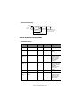
SIGNAL LEVEL
Input/output level
PARAMETER
SYMBOL
MIN.
High (driven)
VIH
2.0
High (floating)
VIHZ
2.7
MAX.
UNITS
Input levels:
V
3.6
V
0.8
V
Low
VIL
Low
OL
0.0
0.3
V
High (driven)
OH
2.8
3.6
V
VCRS
1.3
2.0
V
Output levels:
Output signal crossover
voltage
Interface specifications > 22
Signalling levels
Signalling Levels
Bus State
Required
Acceptable
Differential “1”
(D+)-(D-)> 200mV and D+ > VIH(min)
Differential “0”
(D-)-(D+)> 200mV and D- > VIH(min)
(D-)-(D+)> 200mV
Single-ended 0 (SE0)
D+ and D- < VIL(max)
D+ and D- < VIH(min)
Data J state:
Low-speed
Full-speed
Differential “0”
Differential “1”
Data K state:
Low-speed
Full-speed
Differential “1”
Differential “0”
Idle state:
Low-speed
Full-speed
D- > VIHZ(min) and D+ < VIL(max)
D+ > VIHZ(min) and D- < VIL(max)
Resume state
Data K state
Start-ofPacket (SOP)
Data lines switch from Idle to K state
End-of-Packet (EOP)
SE0 for ≥ 1 bit time1 followed by a J
state for 1 bit time
Disconnect
(at downstream port)
SE0 for ≥ 2.5µs
Connect
(at downstream port)
Idle for ≥ 2ms
Idle for ≥ 2.5µs
Reset
D+ and D- < VIL (max) for ≥ 10ms
D+ and D- < VIL (max) for ≥ 2.5µs
(D+)-(D-)> 200mV
D- > VIHZ(min) and D+ < VIH(min)
D+ > VIHZ(min) and D- < VIH(min)
SE0 for ≥ 1 bit time1 followed by a J
state
NOTE
1. The width of EOP is defined in bit times relative to the
device type receiving the EOP. The bit time is
approximate.
Interface specifications > 23
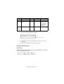
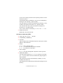
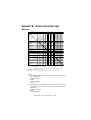
TIMING CHART
Packet voltage levels
VOH(min)
VIH(min)
VIL(max)
VOL(max)
VSS
Bus Idle
SOP
Last Bit
of Packet
First Bit
of Packet
Bus Driven to
SE0 J State at end
of EOP
Portion
Bus Floats
of EOP
Bus Idle
VOH(min)
VIH(min)
VIL(max)
VOL(max)
VSS
Disconnect detection
D+/DVIHZ(min)
VIL
D-/D+
VSS
‡2.5µs
Device
Connected
Disconnect
Detected
Full-speed device connect detection
D+
VIH
D-
D-/D+
VSS
‡2.5µs
Device
Connected
Connect
Detected
Interface specifications > 24
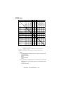
Differential data jitter
TPERIOD
Crossover
Points
Differential
Data Lines
(VCRS)
Consecutive
Transitions
N* TPERIOD + TxDJ1
TPERIOD = 12Mbps(–0.25%)
TxDJ1 = Min-3.5ns~Max3.5ns
TxDJ2 = Min-4ns~Max4ns
Paired
Transitions
N* TPERIOD + TxDJ2
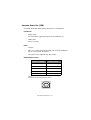
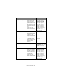
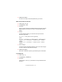
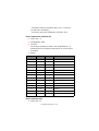
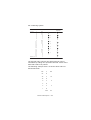
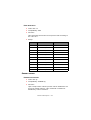
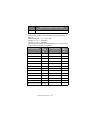
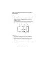
OPTION INTERFACE SPECIFICATIONS
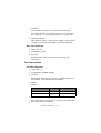
INTERFACE SIGNALS
PIN
NO.
SIGNAL
CODE
SIGNAL
1
Protective Ground
PG
—
2
Transmitted Data
TD
From printer
Data from
printer
3
Received Data
RD
To printer
Data to printer
4
Request to Send
RTS
From printer
Signal to
indicate printer
cannot receive
data in printer
Busy/Ready
protocol
Data Set Ready
DSR
To printer
Indicates that
data can be sent
(Printer receives
data after
confirming this
signal as a
SPACE.)
7
Signal Ground
SG
11
Supervisory Send
Data
SSD
Note 2
6
Note 3
Note 2
—
From printer
Interface specifications > 25
FUNCTION
Frame ground
Signal ground
Signal to
indicate printer
cannot receive
data in printer
Busy/Ready
protocol
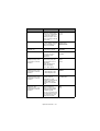
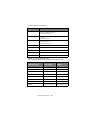
PIN
NO.
SIGNAL
CODE
SIGNAL
FUNCTION
20
Data Terminal
Ready
DTR
From printer
Signal to
indicate printer
cannot receive
data in printer
Busy/Ready
protocol
Note 2
5, 8 to
10, 12
to 19,
21 to 25
—
—
—
Unused
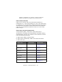
NOTE
1. Connector pin arrangement for above:
13
1
25
14
(Viewed from interface cable side)
2. SSD signal output can be selected from pins 4, 11, 20 by
the Menu.
3. DSR signal valid/invalid can be set by Menu.
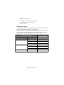
ELECTRICAL CHARACTERISTICS
Signal levels
RS-232C interface signal levels are as specified below, and meet
the EIA Standard RS-232C:
–15 to –3 V: LOW = OFF = LOGIC “1”
+15 to + 3 V: HIGH = ON = LOGIC “0”
Interface specifications > 26
Line driver
Equivalent to SN75188
OUTPUT
INPUT
+9V
OUTPUT
+3V
-3V
-9V
NOTE
The above figures are the standard values for a load of
3 Kohm, 15 pF and a driver source level of ±9 V.
Line receiver
Equivalent to SN75154
INPUT
OUTPUT
+12V
+3V
-3V
-12V
INPUT
NOTE
If the power on the input side is OFF, the output of the receiver
becomes high (+2.4 V or more) at TTL level.
Interface specifications > 27
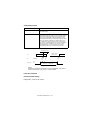
INTERFACE TIMING CHARTS
Receiving timing chart
DSR signal
HIGH
LOW
Start bit
Stop bit
HIGH
RD
LOW
0.5 bit
More than 0 µs
More than 300 µs
NOTE
DSR signal valid/invalid can be set by the Menu.
SSD signal timing chart
Data
Stop bit
RD
HIGH
LOW
Start bit
0.5 bit
MAX 5 ms
SSD
BUSY
READY
RECEIVING MARGIN
Receiving margin is more than 37% at any baud rate.
DESCRIPTION OF COMMUNICATION PROCEDURES
Two types of protocol can be selected by menu communication
procedures: READY/BUSY and X-ON/X-OFF.
Interface specifications > 28
INTERFACE CONTROL CODE
The following function codes are used in the high-speed serial
interface:
COMMAND
CODE
DC1
(17)D (11)H
DC3
(19)D (13)H
NOTE
Characters to be printed according to the parity error
indication code (40)H will differ depending on the setting of the
printer character set. Refer to the printer User’s Guide.
Ready/Busy protocol
Block format
Free
Error indication
The parity error indication is printed as character
40(H).
Busy state indication
The busy signal turns on (becomes Busy) when the
space in the interface buffer has become less than
256 bytes. The busy signal turns off (becomes
Ready) after 200 ms or 1 second has passed if 256
bytes have recovered within 200 ms or 1 second. If
the recovery time exceeds 200 ms or 1 second, the
busy signal turns off (becomes Ready) immediately
after the recovery has occurred.
Timing chart
RD
DATA 1
DATA 2
8K
Threshold of the
characters in
the buffer
512
0
SSD
ON (BUSY)
OFF (READY
200 ms or 1 second minimum
Interface specifications > 29
X-ON/X-OFF protocol
Block format
Free
Error indication
The parity error indication character is converted
into code 40(H).
Busy state indication
The DC3 will be sent to the transmission side
immediately after the space in the interface buffer
has become less than 256 bytes to indicate that
receiving is impossible. The transmission of the
DC3 stops when data receiving has stopped. If the
recovery time for 256 bytes is within 200 ms or
1 second after the DC3 is sent, DC1 will be sent
200 ms or 1 second after the recovery to indicate
that receiving is possible. If the recovery time
exceeds 200 ms or 1 second, the DC1 is sent
immediately after the recovery has occurred.
Timing chart
256 characters or less
BUSY state
PRINTING
DC-3
DC-3
DC-3
TD
Waiting for BUSY
state to be free
DATA 1
DATA
DC1
RD
ON
OFF
200 ms or 1 second minimum
NOTE
If data is transferred when the printer is still BUSY, the printer
sends a DC3 code every time it receives data.
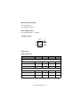
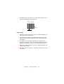
LOCAL TEST FUNCTION
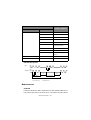
Circuit Test mode setting
Diagnostic: Test set by menu
Interface specifications > 30
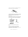
Test connector: Connect the test connectors as shown below to
the interface connectors.
2
TD
RD
RTS
Equivalent to Cannon DB-25P
CTS
CD
SSD
DTR
3
4
5
8
11
20
6
DSR
Circuit Test mode function
After the settings outlined in Circuit Test mode setting are
completed and power is turned on, the serial interface checks the
message buffer memory and interface driver and receiver
circuits, then prints all characters. To start and stop this test,
press the SEL switch on the front of the printer. Details of this
test are explained below.
1.
Print the program revision with two numerical characters.
2.
Print “LOOP TEST.”
3.
Check memory for message buffer.
Print “GOOD” if memory check is OK, and print “BAD” if
memory check fails.
4.
Output LOW to DTR, RTS, and SSD signals. If a CTS, DSR,
or CD signal is HIGH, print “IF BAD”. If the CTS, DSR, and
CD signals are all LOW, print “IF GOOD”.
Output HIGH to DTR, RTS, and SSD signals. If a CTS, DSR,
or CD signal is LOW, print “IF BAD.” If the CTS, DSR and
CD signals are all HIGH, print “IF GOOD.”
5.
Transmit characters from code 20H to 7FH by TD signals.
At the same time, characters are received from the RD
signal and stored in the message buffer.
6.
Print the characters that were stored in the message
buffer as indicated in Step 5.
7.
Repeat from Step 1.
Interface specifications > 31
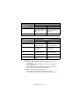
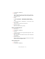
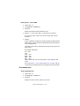
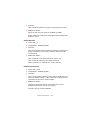
OPERATOR INTERFACE
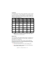
OPERATOR PANEL FUNCTIONS
The operator panel button switches and lamps are located as
follows:
Button switch functions depend on the printer state which can be
any one of:
> Print Mode (for a summary of print modes and features
see “Appendix B – Print modes/features” on page 168.)
> Hex Dump Mode
> Menu Mode
> Test Mode
> Maintenance Mode 1 (not for use by general users)
> Maintenance Mode 2 (not for use by general users)
PRINT MODE
> Without pressing the SHIFT switch:
PRINTER STATE
SWITCH
SEL
SHIFT
LF
SELECT
CONT. FORMS
Sets printer off line
CUT-SHEET
Sets printer off line
Changes functions (see below)
Performs a line feed
Operator interface > 32
Performs a line feed
PRINTER STATE
SWITCH
SELECT
CONT. FORMS
CUT-SHEET
FF/LOAD
Feeds forms or loads
paper
Ejects paper
TEAR
Feeds paper to the tear
or print position
Invalid
PARK
Feeds paper in the
reverse direction
Ejects paper
PRINTER STATE
SWITCH
SEL
DESELECT
CONT. FORMS
CUT-SHEET
Sets printer on line
SHIFT
Sets printer on line
Changes functions (see below)
LF
Performs a line feed
Performs a line feed
FF/LOAD
Feeds forms or loads
paper
Feeds forms or ejects
paper
TEAR
Invalid
Invalid
PARK
Feeds paper in the
reverse direction
Ejects paper
> While pressing the SHIFT switch:
PRINTER STATE
SWITCH
SELECT
CONT. FORMS
CUT-SHEET
SEL
Switches between Menu
and Normal modes
Switches between Menu
and Normal modes
LF
Adjusts the TOF position
(reverse fine
increments)
Adjusts the TOF position
(reverse fine
increments)
FF/LOAD
Adjusts the TOF position
(fine increments)
Adjusts the TOF position
(fine increments)
Operator interface > 33
PRINTER STATE
SWITCH
SELECT
CONT. FORMS
CUT-SHEET
TEAR
Switches between
quiet, high impact and
normal print modes
(Note 1)
Switches between
quiet, high impact and
normal print modes
(Note 1)
PARK
Invalid
Invalid
PRINTER STATE
SWITCH
DESELECT
CONT. FORMS
CUT-SHEET
SEL
Switches between Menu
and Normal modes
Switches between Menu
and Normal modes
LF
Adjusts the TOF position
(reverse fine
increments)
Adjusts the TOF position
(reverse fine
increments)
FF/LOAD
Adjusts the TOF position
(fine increments)
Adjusts the TOF position
(fine increments)
TEAR
Invalid
Invalid
PARK
Sets the TOF position
(Note 2)
Sets the TOF position
(Note 2)
NOTE
1. Pressing TEAR while holding down SHIFT changes the
print mode.
Press TEAR once while holding down SHIFT: switches to
quiet print mode.
Press TEAR twice while holding down SHIFT: switches to
normal print mode (returns to the default).
2. PARK is used to set the TOF position.
Press PARK: The setting is valid until power off.
Hold down PARK: The setting is saved in the Flash-ROM.
Operator interface > 34
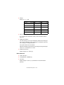
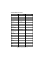
HEX DUMP MODE, MENU MODE, TEST MODE
SWITCH
MENU
TYPES
SEL
SHIFT
LF
FF/LOAD
TEAR
PARK
X
X
O
X
X
X
Activates Self
Test mode
X
X
O
O
X
X
Performs skip/
continuous
pattern
X
X
X
X
X
O
Activates
Rolling ASCII
(1 page)
O
X
X
O
X
X
Activates Hex
Dump mode
O
X
X
X
X
X
Activates Menu
mode
O
O
X
X
X
X
Sets Menu
factory default
setting
O
X
O
X
X
X
Activates
Maintenance
Mode 1
(Note 1)
O
X
O
X
O
X
Activates
Maintenance
Mode 2
(Note 1)
NOTE
1. When a Maintenance Mode is launched, the SEL lamp
lights and waits for the switch to be pressed.
Operator interface > 35
MAINTENANCE MODE 1
SWITCH
MENU
TYPES
SEL
SHIFT
LF
FF/LOAD
TEAR
PARK
Z
X
X
X
O
X
Activates
Maintenance
Menu mode
X
X
O
X
Z
X
Activates
Registration
Menu mode
MAINTENANCE MODE 2
SWITCH
SEL
SHIFT
LF
FF/LOAD
TEAR
PARK
X
X
Z
X
O
X
MENU
TYPES
Activates
Flash Loading
mode
NOTE
The above mode appears by pressing the switch marked O,
releasing the switch marked X and then turning ON the power.
The switch is invalidated when pressed in any other
combination.
After launching each mode, temporarily release all switches
then press the switch marked Z and the switch marked O to
launch the local function.
Operator interface > 36
LAMP FUNCTIONS
LAMP
COLOUR
ON
OFF
BLINKING
SEL
Green
SELECT
(data
receiving
enable)
state
DESELECT
(data
receiving
impossible)
state
Recovery impossible
alarm state (Note 1).
Keep printing data
state.
ALARM
Red
Paper end
state
Paper
existing
state
Cut sheet removal
standby state.
Recovery impossible
alarm state (Note 1).
Paper jam state.
Media switching
alarm state.
MENU
Green
MENU
mode
Normal print
mode
LF and SP motor
protecting alarm.
QUIET
Green
Quiet print
mode
Normal print
mode
High multipart print
mode.
POWER
Green
Power ON
state
Power OFF
state
Power save mode
(1s ON/1s OFF).
NOTE
1. In recovery impossible alarm state, both SEL and ALARM
lamps are blinking.
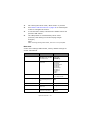
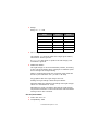
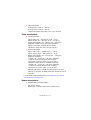
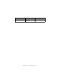
ALARM/ERROR INDICATIONS
RECOVERABLE ALARMS
LED
SEL
ALARM
MENU
R
O
R
Paper Lever
B
R
Paper Jam (Load jam,
Ejection jam)
B
R
ALARM
Paper End
Head Temperature
R
R
B
SPACE/LF MOTOR
Temperature
R
R
B
Operator interface > 37
NOTE
O: LED continuously ON
B: LED blinking (500 ms ON, 500 ms OFF)
R: Current LED indication retained
Blank: LED OFF
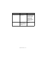
UNRECOVERABLE ALARMS
Unrecoverable alarms are shown below. The numbers of blinks of
the alarms indicate the states of the alarms.
Alarm indication consists of main blinking and sub-blinking. Main
blinking is the concurrent blinking of the SEL and ALARM LEDs
and sub-blinking is the blinking of only the SEL LED.
ALARM INDICATION
ALARM CONTENTS
MAIN BLINKING
SUB-BLINKING
1
1
Head homing alarm
2
Spacing alarm
3
Roller alarm
1
Program ROM alarm
2
CG ROM alarm
3
Flash ROM alarm
1
DRAM alarm
2
3
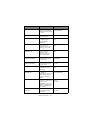
Operator interface > 38
ALARM INDICATION
ALARM CONTENTS
MAIN BLINKING
SUB-BLINKING
4
1
CPU (inside RAM) alarm
2
Manual reset alarm
3
NMI alarm
4
CPU address alarm
5
DMA address alarm
6
General invalid
instruction alarm
7
Slot alarm
8
Watchdog timer alarm
9
Invalid interrupting
alarm
5
1
F/W alarm
9
1
Head A/D error
LED blink time periods
SEL
ON
OFF
ALARM
ON
OFF
T1 T2
T1 T2
T3
Main blinking
T4
Sub-blinking
1 Cycle
T1=T2=250 msec
T3=T4=750 msec
MENU SELECTION
OVERVIEW
Features selected in Menu mode become the default features for
the printer each time it is powered on. The Menu function allows
Operator interface > 39
features to be activated without the use of a software command
but software commands override Menu settings.
NOTE
Maintenance Menu items are not accessible to day-to-day
users.
BUTTON SWITCH FUNCTIONS
SWITCH
FUNCTION
LF
Moves forward through the menu items.
When the last item is selected, the first one will
come up on pressing LF.
SHIFT + LF
Moves backward through the menu items.
When the first item is selected, the last one will
come up on pressing LF.
FF/LOAD
Moves forward through the values of a menu item.
When the last value is selected, the first one will
come up on pressing FF/LOAD.
SHIFT + FF/LOAD
Moves backward through the values of a menu
item.
When the first value is selected, the last one will
come up on pressing SHIFT + FF/LOAD.
SHIFT + SEL
Exits the Menu mode.
The printer enters the initial state as at power on.
PARK
The first menu item is printed after all the menu
items are printed.
OPERATION
1.
To enter Menu Mode:
(a)
If the printer power is OFF, while holding down the
SEL button turn the power ON.
(b)
If the printer power is ON, press the SHIFT and SEL
buttons together.
To enter Maintenance Menu mode.
(a)
Hold down the SEL and LF switches and turn the
power ON to activate Maintenance Mode.
(b)
After Maintenance Mode is enabled, hold down the
SEL switch and press the TEAR switch.
Operator interface > 40
2.
On entering the Menu mode, “Menu Print?” is printed.
3.
See “Button switch functions” on page 40 for a description
of how to navigate the menus.
4.
To exit the Menu mode, hold down the SHIFT switch and
press the SEL switch.
5.
The TOF position is not affected by Menu mode.
(However, TOF setting is executed if page length
changes.)
NOTE
When entering/exiting Menu Mode, the user is not prompted.
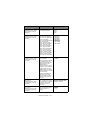
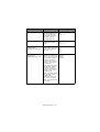
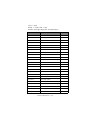
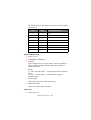
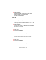
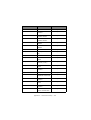
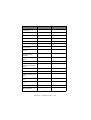
MENU ITEMS
In the menu settings tables below, factory default settings are
shown emboldened.
ITEM
FUNCTION
SETTING
Emulation Mode
Select EPSON LQ mode,
IBM PPR mode, or IBM
X24 AGM mode.
IBM PPR
IBM AGM
EPSON LQ
Print Mode
Select quality of ANK
characters.
LQ Courier
LQ Roman
LQ Swiss
LQ Swiss Bold
LQ Orator
LQ Gothic
LQ Prestige
LQ OCR-A
LQ OCR-B
Utility
HSD
Pitch
Select character pitch.
10 CPI, 12 CPI, 15 CPI,
17.1 CPI, 20 CPI
Proportional Spacing
Select whether to use
proportional spacing or
not.
Yes
No
Style
Select either font style.
Normal, Italics
Size
Select the character
scale size.
Single, Double
Character Set
Select either ANK
character code table.
Set I
Set II
Operator interface > 41
ITEM
FUNCTION
SETTING
Language Set
Select a language
character set.
ASCII, French,
German, British, Danish
I, Swedish I, Italian,
Spanish I, Japanese,
Norwegian, Danish II,
Spanish II, Latin
American, French
Canadian, Dutch,
Swedish II, Swedish III,
Swedish IV, Turkish,
Swiss I, Swiss II,
Publisher
Zero Character
Select either print font
pattern to receive a
zero character located
at 30H in ANK code or
at AA30H in a singlebyte code.
Unslashed
Slashed
Operator interface > 42
ITEM
FUNCTION
SETTING
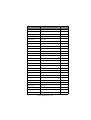
Code Page
Select a code page.
USA
Canada French
Multilingual
Portugal
Norway
Turkey
Greek_437
Greek_869
Greek_928
Grk_437 CYPRUS
Polska Mazovia
Serbo Croatic I
Serbo Croatic II
ECMA-94
Hungarian CWI
Windows Greek
Windows East Europe
Windows Cyrillic
East Europe Latin II852
Cyrillic I-855
Cyrillic II-866
Kamenicky (MJK)
ISO Latin 2
Hebrew NC (862)
Hebrew OC
Turkey_857
Latin 5 (Windows
Turkey)
Windows Hebrew
Ukrainian
Bulgarian
ISO Latin 6 (8859/10)
Windows Baltic
Baltic_774
KBL-Lithuanian
Cyrillic Latvian
Roman-8
Icelandic-861
Multilingual 858
ISO 8859-15
Greek_737
Asmo449+
Asom708
Arabic864
Windows Arabic
POL 1
Slashed Letter 0
Set whether to convert
slashed 0 located at
9BH and 9DH in USA
code page or not.
Yes
No
Operator interface > 43
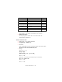
ITEM
FUNCTION
SETTING
Multi Pass
Select the printing
direction when doubleheight print data exists
in a line.
Bi-directional
Uni-directional
Rcv Buffer
Select size of the
received buffer.
0, 2 K, 32 K, 64 K
Print Suppress Effective
Set whether to enable
or disable a print
suppress setup
command.
Yes
No
Auto LF
Select whether to
perform auto LF
operation or not upon
receiving a CR code.
Yes
No
Auto CR
*IBM PPR only
Select whether to
perform auto CR
operation upon
receiving a carriage
return command.
Yes
No
SI Select Pitch (10CPI)
*IBM PPR/AGM only
Set how to handle an SI
command received in
10 CPI mode.
15 CPI
17.1 CPI
SI Select Pitch (12CPI)
*IBM PPR/AGM only
Set how to handle an SI
command received in
12 CPI mode.
12 CPI
20 CPI
Reset Inhibit
Set whether to enable
or disable an initial
command.
No
Yes
Select Language Set
*EPSON only
Set whether to enable
or disable a
combination of the code
page setting and the
language setting by
menu.
Combined
Code Page Only
Impact Mode
Select print mode on
power on. (This item is
referred to on
initialisation only by IPRIME or power on but
not by an initialisation
command.)
Normal
Quiet
Hi Copy
Print Direction
Command
Select the validity of a
one-way print setup
command.
Valid
Invalid
Operator interface > 44
ITEM
FUNCTION
SETTING
Power Save Time
Set idle time to enter
power save mode.
5 min, 10 min, 15 min,
30 min, 60 min
PE Detection
Select whether to
detect paper end or not.
OFF
ON
Table Print
Set whether to divide a
path or not to print on
occasions when printing
by the same headpin
continues for 3 in or
more in the same print
block.
Standard
Special
Line Spacing
Select line feed pitch.
6 LPI
8 LPI
Page Width
Set width of a line to
determine the number
of ANK (10CPI)
characters to be
printed. With this
setting, the right
margin is set. For
reduced-size prints, at
75 % or 50%, 136
characters are printed.
10.6 in
8 in
Form Tear-Off
Select manual or auto
as the method to
advance a continuous
form to the form tearoff position.
Off
500 ms
1 sec
2 sec
Skip Over Perforation
Select whether to skip
over perforation or not.
(When a skip over
perforation setup
command is received,
the received command
is given priority.)
Yes
No
Page Length
(Continuous)
Select the length of a
continuous form.
3.5 in, 4 in, 5.5 in, 6 in,
7 in, 8 in, 8.5 in, 11 in,
11 2/3 in, 12 in, 14 in,
17 in, 5 in, 3 in, 3.25 in
Operator interface > 45
ITEM
FUNCTION
SETTING
TOF (Continuous)
Select the reference
position for the TOF
position when auto
loading continuous form
paper from the rear of
the printer. (Up to the
mid-section of
characters in the first
line.)
“1Chr. Set Pos.” is
printed if the TOF
position is set by using
SHIFT + PARK switches.
2.12 mm (1/12 in)
4.23 mm (1/6 in)
6.35 mm (1/4 in)
8.47 mm (1/3 in)
10.58 mm (5/12 in)
12.7 mm (1/2 in)
14.82 mm (7/12 in)
16.93 mm (2/3 in)
19.05 mm (3/4 in)
21.17 mm (5/6 in)
23.28 mm (11/12 in)
25.4 mm (1 in)
27.52 mm (13/12 in)
1Chr. Set Pos.
Initial Position
This is the position of
the paper when the
paper is already loaded
at power on. (For
continuous form mode
only.)
Print
Tear OFF
Auto Eject Position
Select a printable area
at the bottom of cut
sheets of paper in cutpaper mode (the
character centre
position).
6.35 mm (1/4 in)
14.8 mm
Page Length (Cut
Sheet)
Select the page length
of cut-paper.
3.5 in, 4 in, 5.5 in, 6 in,
7 in, 8 in, 8.5 in, 11 in,
11 2/3 in, 12 in, 14 in,
16.57 in, 5 in, 3 in,
3.25 in
TOF (Cut Sheet)
Select the reference
position for the TOF
position when feeding
cut-paper in manual
mode. (Up to the midsection of characters in
the first line.)
“1Chr. Set Pos.” is
printed if the TOF
position is set by using
SHIFT + PARK switches.
2.12 mm (1/12 in)
4.23 mm (1/6 in)
6.35 mm (1/4 in)
8.47 mm (1/3 in)
10.58 mm (5/12 in)
12.7 mm (1/2 in)
14.82 mm (7/12 in)
16.93 mm (2/3 in)
19.05 mm (3/4 in)
21.17 mm (5/6 in)
23.28 mm (11/12 in)
25.4 mm (1 in)
27.52 mm (13/12 in)
1Chr. Set Pos.
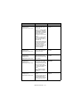
Operator interface > 46
ITEM
FUNCTION
SETTING
Wait Time
Select the waiting time
between setting paper
on the tray and feeding
it while the printer is
waiting for paper to be
fed in cut-paper manual
feed mode.
500 ms
1 sec
2 sec
I-Prime
Select whether to print
or clear buffer contents
upon initialisation by
receiving I-PRIME.
Invalid
Buffer Clear
Buffer Print
Auto Feed XT
*EPSON only
Set the validity of an
Auto Feed XT signal.
Valid
Invalid
I/F Bi-Direction
Set whether to return a
device ID or not in
accordance with
IEEE1284.
Enable
Disable
Parity
*Displayed only when
connected to a serial
interface.
Select presence or
absence of parity bit
and whether even or
odd parity.
None
Odd
Even
None: No parity bit
Odd: Odd parity
Even: Even parity
Serial Bits
*Displayed only when
connected to a serial
interface.
Select the data length.
Protocol
*Displayed only when
connected to a serial
interface.
Select an I/F Busy
control method.
Diagnostic Test
*Displayed only when
connected to a serial
interface.
Select whether to
perform input/output
diagnosis of RS-232C
interface signals.
7: Data length 7 bits
8: Data length 8 bits
7 Bits
8 Bits
Ready/Busy
X-ON/X-OFF
Ready/Busy: Busy
control by a DTR signal
X-ON/X-OFF: Busy
control by a CD3/DC1
code
No: Do not execute the
self diagnostic function
Yes: Execute the self
diagnostic function
Operator interface > 47
No
Yes
ITEM
FUNCTION
SETTING
Busy Line
*Displayed only when
connected to a serial
interface.
Set a Busy Line setting
of a serial interface.
SSDSSD+
DTR
RTS
Baud Rate
*Displayed only when
connected to a serial
interface.
Select the data baud
rate from the options.
300 BPS
600 BPS
1200 BPS
2400 BPS
4800 BPS
9600 BPS
19200 BPS
38400 BPS
DSR Signal
*Displayed only when
connected to a serial
interface.
Select the validity of the
received data.
300: Sets the data baud
rate to 300 BPS
600: Sets the data baud
rate to 600 BPS
1200: Sets the data
baud rate to 1200 BPS
2400: Sets the data
baud rate to 2400 BPS
4800: Sets the data
baud rate to 4800 BPS
9600: Sets the data
baud rate to 9600 BPS
19200: Sets the data
baud rate to 19200 BPS
38400: Sets the data
baud rate to 38400 BPS
Valid
Invalid
Valid: Checks the status
of a DSR signal. The
data received while the
DSR signal is in the
SPACE state is
determined to be valid.
If data is received while
a DSR signal is in the
MARK state, the data is
determined to be invalid
and discarded.
Invalid: Regardless of
the status of a DSR
signal, all the received
data is determined to
be valid.
DTR Signal
*Displayed only when
connected to a serial
interface.
Set a method to switch
a DTR signal of a serial
interface, by select/
deselect or fix it to
power on.
Ready on Power UP
Ready on Select
Busy Time
*Displayed only when
connected to a serial
interface.
Set the minimum time
between BUSY to
READY.
200ms
1 sec
Operator interface > 48
ITEM
FUNCTION
SETTING
TOF Adjustment
(Cut Sheet)
Select an adjustment
value for the reference
position in regard to the
TOF position of cutpaper/passbooks.
-7 – -1
0
+7 – +1
The position moves to
the rear of the form by
[+] and to the top of
the form by [-] in 1/
60 in increments.
Rear Load Adjustment
Select an adjustment
value for the reference
position in regard to the
TOF position of a
continuous form.
-7 – -1
0
+7 – +1
The position moves to
the rear of the form by
[+] and to the top of
the form by [-] in 1/
60 in increments.
Cut Position Adjust
Select an adjustment
value for the position to
cut the end of a
continuous form. (In 1/
90 in increments)
-7 – -1
0
+7 – +1
Registration Low
Adjust the print starting
position on printing in
the reverse direction.
(The position moves to
the right or left in 1/
720 in increments.)
-10 – -1
0
+10 – +1
Registration Normal
Adjust the print starting
position on printing in
the reverse direction.
(The position moves to
the right or left in 1/
720 in increments.)
-10 – -1
0
+10 – +1
Registration High1
Adjust the print starting
position on printing in
the reverse direction.
(The position moves to
the right or left in 1/
720 in increments.)
-10 – -1
0
+10 – +1
Operator interface > 49
ITEM
FUNCTION
SETTING
Registration High2
Adjust the print starting
position on printing in
the reverse direction.
(The position moves to
the right or left in 1/
720 in increments.)
-10 – -1
0
+10 – +1
LF Revise (Cut Sheet)
Adjust a line feed
amount in cut-paper
mode.
-14 – -1
0
+14 – +1
LF Revise (Continuous)
*Displayed in
Maintenance Menu only
Adjust by a line feed
amount when printing a
continuous form from
the rear.
-2
-1
0
+1
+2
Centring For Feed
*Displayed in
Maintenance Menu only
Specify the centring
position for a line feed.
Mode1
Mode 2
Mode 3
Mode 4
Mode 1: Centring to the
8th character position
to feed a continuous
form from the rear by 2
ranges or more and 2/
3-in and more.
Mode 2: Centring to the
5th character position
to feed a continuous
form from the rear by 2
ranges or more and 2/
3-in and more.
Mode 3: Centring to the
8th character position
to feed either
continuous form from
the rear or cut-paper.
Mode 4: No centring by
a line feed.
Operator interface > 50
ITEM
FUNCTION
SETTING
Position Check
*Displayed in
Maintenance Menu only
Switch settings for
position check of the
print head.
Check1
Check 2
Check 1: Homing when
shifting from OFFLINE
to ONLINE by pressing a
switch with a standard
setting and when
exiting the power save
mode.
Check 2: Homing when
printing is started by
data reception after no
operation of
enhancement setting or
printing for more than 3
minutes, and at the
time of cut-paper
feeding or a continuous
form auto loading
(before loading).
SP Check
*Displayed in
Maintenance Menu only
Checking the starting
point of the head for a
continuous form.
Valid
Invalid
Slack Adjust
(Continuous)
*Displayed in
Maintenance Menu only
Set whether to execute
slack adjustment for
paper or not when using
rear tractor.
Valid
Invalid
Centring For Paper Top
(Continuous)
*Displayed in
Maintenance Menu only
Select whether to apply
centring or not to the
30th character before
inserting line feeds until
the top of form goes
over the rear feed roller
in continuous form
mode.
Valid
Invalid
Valid: Apply centring
Invalid: Do not apply
centring
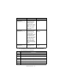
Image Print Speed
*Displayed in
Maintenance Menu only
Select image print
speed.
Normal: Image print at
speed DOWN (80%)
Special: Image print at
normal speed (100%)
Operator interface > 51
Normal
Special
ITEM
FUNCTION
SETTING
CPU Compensation
*Displayed in
Maintenance Menu only
Set data latch timing
and ACK-BUSY signal
output timing with
regard to Centronics
interface signals.
Standard
Special
Standard: Busy signal
output at the centre of
ACK
Special: Busy signal
output at the falling
edge of ACK
I/F Timing Set
*Displayed in
Maintenance Menu only
Set data latch timing
and STB-BUSY signal
output timing with
regard to Centronics
interface signals.
New
Old
Special
New: Busy signal output
and data latch at the
falling edge of STB
Old: Busy signal output
and data latch at the
rising edge of STB
Special: Busy signal
output at the falling
edge of STB and data
latch at the rising edge
of STB
Time Out Print
*Displayed in
Maintenance Menu only
This is to set or cancel
the 150 ms timeout
print mode.
Valid
Invalid
NOTE
1. Cut sheet LF accuracy adjustment, as in the table below
with TOF position as a standard.
SET
VALUE
CONTENTS
-14
Add 1 pitch [0.035 mm (1/720 in)] every -3.88 mm (55/360 in)
-13
Add 1 pitch [0.035 mm (1/720 in)] every -7.83 mm (111/360 in)
-12
Add 1 pitch [0.035 mm (1/720 in)] every -8.46 mm (120/360 in)
-11
Add 1 pitch [0.035 mm (1/720 in)] every -9.10 mm (129/360 in)
-10
Add 1 pitch [0.035 mm (1/720 in)] every -10.01 mm (142/360 in)
-9
Add 1 pitch [0.035 mm (1/720 in)] every -11.00 mm (156/360 in)
Operator interface > 52
SET
VALUE
CONTENTS
-8
Add 1 pitch [0.035 mm (1/720 in)] every -12.48 mm (177/360 in)
-7
Add 1 pitch [0.035 mm (1/720 in)] every -13.97 mm (198/360 in)
-6
Add 1 pitch [0.035 mm (1/720 in)] every -16.29 mm (231/360 in)
-5
Add 1 pitch [0.035 mm (1/720 in)] every -18.62 mm (264/360 in)
-4
Add 1 pitch [0.035 mm (1/720 in)] every -23.28 mm (330/360 in)
-3
Add 1 pitch [0.035 mm (1/720 in)] every -27.94 mm (396/360 in)
-2
Add 1 pitch [0.035 mm (1/720 in)] every -41.91 mm (594/360 in)
-1
Add 1 pitch [0.035 mm (1/720 in)] every -55.88 mm (792/360 in)
0
No LF pitch adjustment
+1
Remove 1 pitch [0.035 mm (1/720 in)] every +55.88 mm (792/360
in)
+2
Remove 1 pitch [0.035 mm (1/720 in)] every +41.91 mm (594/
360 in)
+3
Remove 1 pitch [0.035 mm (1/720 in)] every +27.94 mm (396/
360 in)
+4
Remove 1 pitch [0.035 mm (1/720 in)] every +23.28 mm (330/
360 in)
+5
Remove 1 pitch [0.035 mm (1/720 in)] every +18.62 mm (264/
360 in)
+6
Remove 1 pitch [0.035 mm (1/720 in)] every +16.29 mm (231/
360 in)
+7
Remove 1 pitch [0.035 mm (1/720 in)] every +13.97 mm (198/
360 in)
+8
Remove 1 pitch [0.035 mm (1/720 in)] every +12.48 mm (177/
360 in)
+9
Remove 1 pitch [0.035 mm (1/720 in)] every +11.00 mm (156/
360 in)
+10
Remove 1 pitch [0.035 mm (1/720 in)] every +10.01 mm (142/
360 in)
+11
Remove 1 pitch [0.035 mm (1/720 in)] every +9.10 mm (129/
360 in)
Operator interface > 53
SET
VALUE
CONTENTS
+12
Remove 1 pitch [0.035 mm (1/720 in)] every +8.46 mm (120/360
in)
+13
Remove 1 pitch [0.035 mm (1/720 in)] every +7.83 mm (111/360
in)
+14
Remove 1 pitch [0.035 mm(1/720 in)] every +3.88 mm (55/360
in)
2. Ruled lines print pattern at level print position adjustment
is as follows:
FF
SHIFT+FF
3. For details of the code pages see “Appendix C – Code
pages” on page 170.
REGISTRATION MENU
OVERVIEW
This is a factory shipped configuration to adjust the horizontal
print position correction and is capable of setting the horizontal
print position (see “Menu selection” on page 39.)
OPERATION
To enter registration menu mode:
1.
Hold down the SEL + LF switches and turn on the power
to activate the maintenance mode.
2.
After the maintenance mode is enabled, hold down the
TEAR switch and press the LF switch.
Operator interface > 54
REGISTRATION DETAILS
NO
ITEM
1
Registration
Low
2
Registration
Normal
3
Registration
High 1
4
Registration
High 2
SET
REMARK
+10, +9, ...0...-9, -10
Factory Shipped
Configuration:
+-10/720 in in increments
of 1/720 in.
SELF TEST PRINTING
1.
Start:
While pressing the LF switch, turn on the power.
2.
Stop:
Stop the test by pressing the SEL switch.
3.
Print Pattern:
(a)
Header:
aaaaa EI E
F/W bb.cc
LD ff.gg
ddddddddYR-ee
as defined by:
POSITION &
CHAR. COUNT
DESCRIPTION
DATA
PRINTED
aaaaa
Model name
ML6300FB
bb.cc
Revision no.
00.00 – 99.99
Firmware revision
dddddddd
Part Number
43058201
YR Number
ee
Part Number
01 – 99
ROM-FD Number
ff.gg
Revision no.
00.00-99.99
Boot program
revision
(b)
The first firmware revision is
‘01.xx’ (30)H(31)H(2E)H(x)H(x)H
Operator interface > 55
COMMENTS
(c)
The test pattern is a consecutive printing of ASCII
characters 20H to 7EH in all print quality and pitch
combinations
NUMBER OF CHARACTERS PRINTED PER LINE
80 at 10 CPI
136 CH
96 at 12 CPI
163 CH
120 at 15 CPI
204 CH
137 at 17.1 CPI
233 CH
160 at 20 CPI
272 CH
ROLLING ASCII SELF TEST PRINTING
1.
Start:
Start the continuous rolling ASCII by pressing and holding
the PARK switch then turning the power on.
2.
Stop:
Stop the test by pressing the SEL switch.
3.
Print pattern:
(a)
Header:
aaaaa EI E
F/W bb.cc
LD ff.gg
ddddddddYR-ee
as defined by:
POSITION &
CHAR. COUNT
DESCRIPTION
DATA
PRINTED
aaaaa
Model name
ML6300FB
bb.cc
Revision no.
00.00 – 99.99
Firmware revision
dddddddd
Part Number
43058201
YR Number
ee
Part Number
01 – 99
ROM-FD Number
ff.gg
Revision no.
00.00 - 99.99
Boot program
revision
Operator interface > 56
COMMENTS
(b)
Pattern will be continuous printing of all ASCII
characters.
(c)
The test completes when one print pattern is printed
out.
HEXADECIMAL DUMP MODE
OVERVIEW
Normally a printer prints character patterns that correspond with
the input character code. The printer does not print function
codes or invalid codes. If the printer does not operate normally,
the data sent from the host computer must be checked to
determine if the commands are correct.
In this mode the printer converts input data into hexadecimal
data and prints all the input data, making it is easy to check all
the codes sent from the host computer to the printer.
OPERATION
1.
Entering Hexadecimal Dump mode:
While pressing the SEL+FF/LOAD switches, turn on the
power.
2.
Exiting Hexadecimal Dump mode:
Turn the power OFF
3.
Print pattern:
Hex Data Dump
XXXXXXXXXXXXXXXXXXXXXXXXXXXXXXXX ...................
XXXXXXXXXXXXXXXXXXXXXXXXXXXXXXXX ...................
4.
Printing example:
The following is an example when data is input from the
host computer in the basic format:
Basic: LPRINT CHR$ (&H1B); “0 “; CHR$ (&H1E);
“01234567890 “; CHR$ (&0D); CHR$ (&H0A)
1B 30 1E 30 31 32 33 34 35 36 37 38 39 30 OD OA
.0.01234567890.
Operator interface > 57
FUNCTION
> Prints in 10 CPI Utility mode.
> Both parallel and USB interfaces are available.
> Paper auto Skip Over Perforation (SOP) by menu default
value continuous for both. If SOP is enabled, one inch
from the bottom of the paper will not be printed.
> Printing starts when more than 16 bytes of data are
received (line full).
CONTINUOUS PAPER AUTO-LOADING
Load continuous paper on the tractor (at a position such that the
paper does not cross the paper-end sensor).
In this situation, pressing the FF/LOAD switch starts autoloading.
When the paper does not cross the paper-end sensor within an
8-in feed of the paper, a paper-end state occurs.
The print position of the first data line can be set by menu
function or in first character setting mode.
NOTE
TOF is the position that is set when the operation was
completed properly.
CONTINUOUS PAPER AUTO-PARKING
With continuous paper loaded in continuous paper mode,
pressing the PARK switch starts auto-parking.
When the end of continuous paper is detected by the time the
paper is fed 22 in in reverse, auto-parking finishes and a paperend state is established.
If the end of continuous paper is not detected after a 22-in
reverse feed, autoparking terminates. The position that is set
when the auto-parking terminated becomes TOF.
Pressing the PARK switch again repeats the auto-parking
operation.
The number of reverse movements using the switch is limited to
one.
Operator interface > 58
Do not perform reverse feed if the last sheet of continuous paper
will come off the tractor.
CUT-SHEET PAPER SEMI-AUTO-LOADING
By loading paper on the input tray in cut-sheet mode or while
waiting for cut-sheet feed, semi-auto-loading starts after the
menu-set paper feed wait time (0.5 sec/1.0 sec/2.0 sec) has
elapsed.
Once started, cut-sheet paper is fed until the print position of the
first data line is reached, the printer is placed in the SELECT state
and the operation finishes.
The TOF set at that time is the printing start position of the first
data line.
FORM TEAR-OFF
FUNCTION
Form tear-off allows the user to tear the continuous forms paper
at a desired cut position by advancing the paper to the cutting
edge of the front upper cover.
SET-UP
1.
Conditions:
(a)
2.
Continuous forms paper is loaded into the tractor
feed.
Tear Position:
(a)
Load continuous forms paper.
Press the TEAR switch while On line to move the
paper up to tear position.
(b)
Adjust to the desired tear position using fine LFs.
Operator interface > 59
ACTION
(a)
The paper will advance to the tear-off position
approximately 500ms/1sec/2sec after printing.
(b)
When data is received by the printer or the SEL
switch is pressed to select the printer, the paper will
retract to the user-defined printing position.
(c)
Tear Up/Down operations are alternately executed
by pressing the TEAR switch.
Operator interface > 60
COMMAND DESCRIPTIONS
For a summary of the commands available see “Appendix A –
Command summary” on page 153.
HORIZONTAL CONTROL
CARRIAGE RETURN
> Code: CR
> Compatibility: EPSON LQ/IBM
> Function:
Terminates the print line and returns the print position to
the start of the line.
The data in the print buffer will be printed.
> Additional details:
CR will perform a line feed if auto LF is on. Auto LF can be
set by Menu or control codes.
Double width mode which is designated by SO (and ESC SO
in Epson mode) will be reset.
Auto feed XT signal low – Epson.
HORIZONTAL TAB SET
> Code: ESC D n1 n2 ... nj nk NUL
> Compatibility: EPSON LQ/IBM
> Function:
The tab stops will be set according to the values of n which
specify the character positions, starting from the Left
Margin – Epson and home position – IBM.
> Range:
Range k = 1 – 32 Epson, 1 – 28 IBM
Command descriptions > 61
Range n = 1 – 255
CPI
VALUE
10
105
12
126
15
158
17.1
180
20
211
nj < nk: valid.
nj >= nk: nk invalid – IBM, nk ignored and sequence
terminated – Epson.
> Out of range:
If k = 0 or k > 32 – Epson, k > 28 – IBM
The last value and any following value of n will be ignored.
Maximum n value in each CPI, values larger than
maximum are ignored.
> Additional details:
The tab settings n1, n2, n3, nk must be entered in
ascending order.
Entire command string is terminated with a NUL, CHR$ (0).
MODE
LEFT MARGIN
CHANGE
PITCH CHANGES
Epson
Position adjusted
Position not affected
IBM
Position not affected
Position relative to pitch
Tabs are set at every eighth character after powering up
the printer, receiving an l-PRIME (INIT) signal or executing
an ESC @ (Epson mode only).
Receiving ESC } NULL signal.
Receiving ESC { n signal.
Executing Menu setting.
If n = 0, clear all tabs set.
Command descriptions > 62
Example: ESC D 30 40 1 10 60 70 NUL
IBM mode: 30 40 60 70 valid
Epson mode: 30 40 valid
> Related functions:
Horizontal Tab – HT
HORIZONTAL TAB
> Code: HT
> Compatibility: EPSON LQ/IBM
> Function:
This command causes a skip to the next Horizontal Tab
(HT) position.
> Additional Details:
Epson – Tabs are absolute positions; changes in character
pitch do not change tab positions.
IBM – Tabs are relative to character pitch.
Upon power up the default tabs are set at columns 9, 17,
25, 33... and every eight spaces after that, according to
the default character pitch.
The spaces generated by a horizontal tab will not be
scored.
> Related Functions:
Horizontal tab stop set – ESC D
RESET TAB SETTINGS TO POWER-ON DEFAULT VALUES
> Code: ESC R
> Compatibility: IBM
> Function:
This command sets horizontal tabs at every eighth
character starting at column 9 and clears all vertical tabs.
> Additional details:
The horizontal tabs will be set according to the default
character pitch.
Command descriptions > 63
EXECUTE ABSOLUTE HORIZONTAL DOT POSITION
> Code: ESC $ n1 n2
> Compatibility: EPSON LQ
> Function:
Moves the printhead to the specified absolute horizontal
dot position in a line from the left margin; subsequent data
is printed from this position.
> Range:
In dot position setting, n1 becomes low byte and n2
becomes high byte.
n1, n2 = 0 – 255 (bit7 of n2 is ignored).
Limit:
0 <= n1 + (n2*255) <= 10922 (0/120 – 10922/120 in)
10923 <= n1 + (n2*255) <= 21845 (0/120 – 10922/
120 in)
21846 <= n1 + (n2*255) <= 32767 (0/120 – 10921/
120 in)
> Out of range:
Any position specified beyond the right margin is ignored.
> Additional details:
Dot position = (n1 + n2*256)/60 <= 10.6 in.
The position specified as n1 = n2 = 0 is the left margin.
Dot position is absolute. The character pitch does not affect
the dot position.
This command starts print when specified dot position is
left of the current print position.
Spaces generated by moving the horizontal positioning are
not scored if score is set.
EXECUTE RELATIVE DOT POSITION
> Code: ESC \ n1 n2
> Compatibility: EPSON LQ
Command descriptions > 64
> Function:
This moves the printhead to the dot position from which all
subsequent data is to be printed, relative to the current
position in a line.
> Range:
n1 and n2 specify the dot position; the lower byte is n1 and
the upper byte is n2.
Range n1 and n2 is 0 – 255.
> Out of range:
Defined values beyond the left or right margins are
ignored.
> Additional details:
This relative setting defines the next printing position by
calculating on the basis of the printing position
immediately preceding the input of this code. Printing
starts at a position before or after the previous position at
a dot spacing defined by the selected print mode.
Positive values move the print position to the right and
negative values move it to the left.
Dot position = n1 + n2 * 256.
Physical position = dot position/density = (n1 + n2*256)/
DPI.
With the score mode selected, score is added only for skip
to right.
Actual relative dot positioning depends on the current
mode.
Dots/line:
DPI
VALUE
Utility – All CPI
120
1272
LQ – All CPI & Prop
180
1908
Command descriptions > 65
Example:
DOTS NUMBER
N2
N1
2448
09
90
|
|
|
|
|
|
3
0
3
2
0
2
1
0
1
0
0
0
-1
FF
FF
-2
FF
FE
-3
FF
FD
|
|
|
|
|
|
-2448
F6
70
MOVE RIGHT RELATIVE DOT POSITION
> Code: ESC d n1 n2
> Compatibility: IBM
> Function:
Moves the print position n/120 in to the right from the
current printhead position.
> Range:
Specify dot position following n1 and n2.
n1 is low byte, n2 is high byte.
n1 and n2 range is 0 – 255
Limit 0 <= n1 + (n2*255) <= 1632
> Out of range:
Values beyond the right margin will be ignored.
Command descriptions > 66
> Additional details:
If score is set any horizontal positioning is scored.
MOVE LEFT RELATIVE DOT POSITION
> Code: ESC e n1 n2
> Compatibility: IBM
> Function:
Moves current logical horizontal position to the left (toward
home position) in steps of n/120 in. Prints data in print
buffer.
> Range:
In dot position setting, n1 becomes low byte and n2
becomes high byte.
n1, n2 = 0 – 255 (bit7 of n2 is ignored).
Limit:
0 <= n1 + (n2*255) <= 10922 (0/120 – 10922/120 in)
10923 <= n1 + (n2*255) <= 21845 (0/120 – 10922/
120 in)
21846 <= n1 + (n2*255) <= 32767 (0/120 – 10921/
120 in)
> Out of range:
Current logical horizontal position is set to the left margin
if value is entered beyond left margin.
> Additional details:
No score is added to spaces generated by this command.
LEFT MARGIN SET
> Code: ESC I n
> Compatibility: EPSON LQ
> Function:
Left margin is set at (n) characters from printhead home
position.
Command descriptions > 67
> Range:
Range n = 0 – 255
NAME
PITCH
VALUE
PICA/PROPORTIONAL
10
0 – 105
ELITE
12
0 – 126
–
15
0 – 158
COMPRESSED
17.1
0 – 180
COMPRESSED ELITE
20
0 – 211
COMPRESSED Prop
20
0 – 211
> Out of range:
If n exceeds the maximum value, this command will be
ignored.
> Additional details:
The left margin is set as an absolute position according to
the current character pitch. Changes in character pitch do
not change the margin position.
The print buffer will be cleared.
Maximum difference between left margin and right margin
values is 2 characters for 5 CPI.
> Related functions:
Right margin set – ESC Q n
RIGHT MARGIN SET
> Code: ESC Q n
> Compatibility: EPSON LQ
> Function:
Right margin is set at (n) characters from head home
position.
Command descriptions > 68
> Range:
Range n = 1 – 255
NAME
PITCH
VALUE
PICA/PROPORTIONAL
10
1 – 106
ELITE
12
1 – 127
–
15
1 – 159
COMPRESSED
17.1
1 – 181
COMPRESSED ELITE
20
1 – 212
COMPRESSED Prop
20
1 – 212
> Out of range:
The number “n” must be within the ranges given above,
otherwise it will be ignored.
If n = 0, or is less than or equal to the left margin, this
command is ignored.
> Additional details:
The right margin is set as an absolute position, according
to the current character pitch. Changes in character pitch
do not change the margin setting.
While in proportional mode the character pitch width will
be set in pica character size. (10 CPI = 36 dots)
Any graphics after the right margin are lost.
Setting the right margin clears the print buffer.
Minimum difference between left margin and right margin
values is 5 characters for 5 CPI.
Attempting to print a character beyond the right margin
will print the character on the next line after a line feed and
carriage return are executed.
SET LEFT/RIGHT MARGIN
> Code: ESC X n1 n2
> Compatibility: IBM
Command descriptions > 69
> Function:
Sets the left and right margins in character positions from
the home position by the current character pitch.
> Range:
The ranges for n1 and n2 are:
0 <= n1 <= 255 Left margin
0 <= n2 <= 255 Right margin
n1 < n2
> Out of range:
If n1 or n2 = 0 then the current margin setting is used.
If n2 exceeds the default range n2 will be converted to the
default value.
10 CPI
12 CPI
15 CPI
17.1 CPI
20 CPI
106
127
159
181
212
Value
> Additional details:
The default value of the left margin is the first character.
The margin settings are absolute. Changes in character
pitch do not affect the margin position.
n1, n2 indicate the left and right edges of printable area.
For example, if n1 = 10, n2 = 100, the printable area is
from the 10th column to the 100th column: 91 characters
are printable.
AUTO JUSTIFICATION
> Code: ESC a n
> Compatibility: EPSON LQ
> Function:
The text position/alignment will be set according to one of
the four given modes assigned by n. (n is a Binary value.)
Command descriptions > 70
> Range:
N
JUSTIFICATION
00H
Left
01H
Centre
02H
Right
03H
Full
> Additional details:
n = 0: Left justification is the default or standard format,
in which the left margin is justified and the right margin is
not.
n = 1: The centring command centres a line of text
between the margins. This command is used for headings,
titles and captions.
n = 2: Right justification is the opposite of left justification.
The right margin is justified and the left is not.
n =3: Full justification puts extra spaces where necessary
so that both the left and right margins are justified.
Full justification (n = 3) is performed when data exceeding
75% of printable characters in a line is received at the time
of print start.
BS, DEL, HT are invalid when auto justification is used
except when n = 0.
Print position will be affected by the commands which set
the left/right margin.
NOTE
When using full auto justification, use carriage return at the
end of paragraphs only, not at the end of each line of text.
SET/RESET UNIDIRECTION PRINTING
> Code: ESC U n
> Compatibility: EPSON LQ/IBM
Command descriptions > 71
> Function:
Unidirectional printing, from left to right, or bidirectional
printing will be performed based on the value of n.
> Range:
Range n:
EPSON
IBM
ACTION
01H, 31H, 81H, B1H
ODD
SET Unidirectional
00H, 30H, 80H, B0H
EVEN
RESET (Bidirectional)
> Out of range:
This command will be ignored if n equals a value other than
the values mentioned above.
> Additional details:
Short line seeking is performed in both unidirectional and
bidirectional print modes.
ONE LINE UNIDIRECTIONAL PRINTING
> Code: ESC <
> Compatibility: EPSON LQ
> Function:
Unidirectional printing for one line only will be performed.
> Additional details:
The line is printed from left to right.
Subsequent lines will be printed, bidirectionally, according
to short line seeking priorities logic.
This command returns the printhead to the start of the
print line before printing begins.
SET/RESET HALF SPEED PRINTING
> Code: ESC s n
> Compatibility: EPSON LQ
Command descriptions > 72
> Function:
The printer starts/stops printing at 50% of normal speed
upon receipt of this command depending on the value of n.
> Range:
n = 01H, 31H, 81H, or B1H SET half-speed printing.
n = 00H, 30H, 80H, or B0H SET full speed printing.
> Out of range
This command will be ignored if n equals a value other than
the values mentioned above.
> Additional details:
Half Speed mode can be used to reduce printer noise.
If the print speed is slower than the printer’s physical
lowest speed, the half speed command is ignored and data
is printed at that lowest speed.
BACKSPACE
> Code: BS
> Compatibility: EPSON LQ/IBM
> Function:
Prints the data in the print buffer and moves the printhead
one character to the left according to the character pitch
set.
> Additional details:
If a Multipass character (e.g. double height character)
needs to be printed, after the BS the printer performs a
back space and a LF to the printing position and prints the
character. (Precise printing position is not guaranteed.)
A backspace code given when the printhead is at the left
margin is ignored.
Moves back two character spaces if the printer is in double
width mode.
If clearance between characters is set, BS value will be
character width and clearance.
Command descriptions > 73
In proportional mode:
EPSON LQ – The first character is back spaced by the width
of the proportional character and subsequently by 10 CPI
character width (or reduced 12 CPI character width in
Reduce mode).
IBM – Back space by 12 CPI character width.
ONE CHARACTER DATA DELETE
> Code: DEL
> Compatibility: EPSON LQ
> Function:
Deletes the last character data input into the print buffer.
> Additional details:
If the data which is to be deleted is a SP code, (20)H or
(32)D, one SP code is deleted by this command.
If the data which is to be deleted is in Bit Image Graphics,
this command is ignored.
Horizontal tab or skip is not deleted.
Control codes are not affected.
This command is ignored if auto-justification is set, except
when n = 0.
VERTICAL CONTROL
SET 1/8 INCH FIXED LINE SPACING
> Code: ESC 0
> Compatibility: EPSON LQ/IBM
> Function:
The line spacing is set to 1/8 in.
> Additional details:
This command remains in effect until a new line spacing
command is sent to the printer.
This command does not set the top of form position.
Command descriptions > 74
> Related functions:
LF or CR (and the condition that Auto LF is on) executes 1/
8 in LF.
SET 7/72 INCH FIXED LINE SPACING
> Code: ESC 1
> Compatibility: IBM
> Function:
Line spacing will be set to 7/72 in upon receipt of this
command.
> Additional details:
This command remains in effect until a new line spacing
command is sent to the printer.
This command is used to set line spacing for graphics
printing.
START LINE SPACING
> Code: ESC 2
> Compatibility: IBM
> Function:
The line spacing value which is set by ESC A n will be
activated when ESC 2 is sent.
The line spacing set by Menu is selected if it has not been
stored by ESC A n.
SET 1/6 INCH LINE SPACING
> Code: ESC 2
> Compatibility: EPSON LQ
> Function:
The line spacing is set to 1/6 in.
Command descriptions > 75
> Additional details:
This command remains in effect until a new line spacing
command is sent to the printer.
This command does not set the top of form position.
> Related functions:
LF or CR (and the condition that Auto LF is on) executes 1/
6 in LF.
SET N/60 INCH LINE SPACING
> Code: ESC A n
> Compatibility: EPSON LQ/IBM PPR/IBM AGM
> Function:
Sets line spacing to: n/60 in Epson LQ, n/60 in IBM AGM,
n/72 in IBM PPR
> Range:
Range
n = 0 – 127 Number of 1/60 in increments – Epson
n = 1 – 255 Number of 1/60 in (1/72 in) increments – IBM
> Out of range:
Values of n not within the allowable range will be ignored.
> Additional details:
No line feed will occur when n = 0 in Epson mode. In IBM
mode if n = 0 this command is ignored, and the line
spacing in not changed.
Power on default or l-Prime signal resets the value set by
this command and sets the value determined by the Menu.
Top of form will not be set.
> Related functions:
ESC 2 is used to initiate the selected line spacing for IBM
PPR mode.
Command descriptions > 76
SET N/180 INCH LINE SPACING
> Code: ESC 3 n
> Compatibility: EPSON LQ/IBM PPR/IBM AGM
> Function:
Sets line spacing to: n/180 in Epson, n/216 in IBM PPR,
and n/180 in IBM AGM.
> Range:
Range
n = 0 – 255 Number of 1/180 in increments – Epson, IBM
AGM
n = 1 – 255 Number of 1/216 in increments – IBM PPR
> Additional details:
Power-on default or l-Prime signal resets the value set by
this command and sets the value which is determined by
the Menu.
No line feed occurs when n = 0 in Epson, IBM AGM mode.
In IBM PPR mode if n = 0 this command is ignored.
Top of form will not be set.
> (f) Related functions:
LF, VT, or CR (and when Auto LF is on) executes
predetermined LF.
ESC [ \ sets the spacing increment in IBM mode.
SET N/360 INCH FINE LINE SPACING
> Code: ESC [ n
> Compatibility: EPSON LQ
> Function:
Sets line spacing to n/360 in.
> Range:
Range n = 0 – 255 Number of 1/360 in increments.
Command descriptions > 77
> Additional details:
Power on default or l-Prime signal resets the value set by
this command and sets the value which is determined by
the Menu.
No line feed occurs when n = 0.
Top of form will not be set.
> Related functions:
LF, VT, or CR (and the condition that Auto LF is on)
precedes predetermined LF.
SET N/360 INCH LINE SPACING
> Code: ESC % 8 n
> Compatibility: IBM
> Function:
Sets line spacing to n/360 in.
> Range:
Range n = 1 – 255, Number of 1/360 in increments.
> Additional details:
Power on default or l-Prime signal resets the value set by
this command and sets the value which is determined by
the Menu.
This command is ignored when n = 0.
Top of form will not be set.
> Related functions:
LF, VT, or CR (and the condition that Auto LF is on)
precedes predetermined LF.
LINE FEED
> Code: LF
> Compatibility: EPSON LQ/IBM
Command descriptions > 78
> Function:
This command causes the data in the print buffer to be
printed followed by a movement to the next print line
based on the current line spacing.
> Additional details:
A carriage return will also be executed; in IBM PPR mode
auto CR must be set for CR to be executed.
Line spacing pitch will be set by ESC A n, ESC 0, ESC 2, ESC
3 n, and ESC [ n. Otherwise, the LF pitch will be set by
Menu when power is on or an l-Prime signal is received.
This code will cancel enlarged character mode set by the
ESC SO (Epson mode only) and SO code. If there is no data
before the LF code or only spaces before this code, only
line feed is performed.
SET/RESET AUTOMATIC LINEFEED
> Code: ESC 5 n
> Compatibility: IBM
> Function:
Enables/disables automatic line feed. The printer performs
an automatic LF each time it receives a carriage return
(CR).
> Range:
If n = ODD, SET automatic LF.
If n = EVEN, RESET automatic LF.
> Out of range:
The line feed is executed for the current line spacing
setting.
FINE LINE FEED (N/180 INCH)
> Code: ESC J n
> Compatibility: EPSON LQ/IBM PPR/IBM AGM
Command descriptions > 79
> Function:
Immediate line feed is executed without changing the
current line spacing.
n/180 in Epson LQ
n/180 in IBM AGM
n/216 in IBM PPR
> Range:
n = 0 – 255, Number of 1/180 in increments – Epson
n= 1 – 255, Number of 1/180 in (1/216 in) increments –
IBM
> Additional details:
The contents of the buffer are printed without a Carriage
Return. (The printhead does not move to the left margin.)
In IBM mode if auto CR is selected by Menu a carriage
return will be performed.
This command does not need a cancel code, since it is
executed only once.
No feed is performed when n = 0. (Ignored in IBM mode)
> Related functions:
Double width set by SO (or ESC SO in Epson mode) will not
be reset.
ESC [ \ sets the spacing increment for IBM mode.
FINE LINE FEED (N/360 INCH)
> Code: ESC ] n
> Compatibility: EPSON LQ
> Function:
A n/360 in immediate line feed is executed without
changing the current line spacing.
> Range:
Range n = 0 – 255, Number of 1/360 in increments.
Command descriptions > 80
> Additional details:
The contents of the buffer will be printed without a CR.
(Carriage does not move to the home position.)
No line feed occurs when n = 0.
Top of form will not be set.
> Related functions:
Double width set by SO (or ESC SO in Epson mode) will not
be reset.
FINE LINE FEED (N/360 INCH)
> Code: ESC % 4 n
> Compatibility: IBM
> Function:
A n/360 in immediate line feed is executed without
changing the current line spacing.
> Range:
Range n = 0 – 255, Number of 1/360 in increments.
> Additional details:
The contents of the buffer will be printed without a CR.
(Carriage does not move to the home position.)
No line feed occurs when n = 0.
Top of form will not be set.
> Related functions:
Double width set by SO will not be reset.
REVERSE LINE FEED
> Code: ESC j n
> Compatibility: EPSON LQ
Command descriptions > 81
> Function:
Once this command is received the printer will execute an
immediate reverse line feed, which will be executed only
once for each time this command is sent.
> Range:
Range n = 0 – 255
> Additional details:
The printer will perform an n/180 in reverse line feed each
time this command is sent.
The current line spacing will not be changed.
It must not exceed TOF whether or not there is perforation
skip.
NOTE
It is not recommended to use the pull tractor option feed unit
when reverse line feeds are required.
REVERSE LINE FEED
> Code: ESC ]
> Compatibility: IBM
> Function:
Prints data in the print buffer, then performs reverse line
feed. Reverse line feed is also performed when no print
data is stored in the buffer.
Linefeed amounts conform to those which are set using
ESC 0, ESC 1, ESC 2, ESC 3 Pn, ESC A Pn, and ESC % 8
Pn. When not set after the power is turned on, the amount
of line feed equates to a menu-set value.
> Additional Details
Printing and line feed are performed irrespective of AUTO
CR in the menu (a carriage return is not inserted).
One-line horizontal expansion by SO and ESC SO is not
cancelled (also it is not cancelled when AUTO CR is valid).
Command descriptions > 82
When the amount of line feed is doubled by setting using
the ESC [ @ command, a single reverse line feed is
performed.
A new line does not start beyond the TOF position.
Page length is controlled.
FORM FEED
> Code: FF
> Compatibility: EPSON LQ/IBM
> Function:
Upon receipt of this command the printer prints the data in
the print buffer and carries out a carriage return, then
feeds the paper to the next TOF position.
> Additional details:
Factory setting of form length is eleven (11) in. (Menu).
Pressing the FORM FEED button on the operator panel
always feeds the paper forward to the next top of form
position.
FF will be performed to the next top of form position even
when the FF is received at the top of form position.
Double width set by SO (or ESC SO in Epson mode) will be
reset.
> Related functions:
TOF will be set on power-up or l-Prime (or ESC 4 in IBM
mode).
Receiving ESC } NULL signal.
Receiving ESC { n signal.
Executing Menu setting.
VERTICAL TAB
> Code: VT
> Compatibility: EPSON LQ/IBM
Command descriptions > 83
> Function:
Upon receipt of this command the printer will print out
what is in the buffer then move the paper to the next
preprogrammed tab stop.
> Additional details:
If vertical tabs are not set this command will function the
same as: CR in Epson mode, LF in IBM mode.
Executing more than the number of vertical tabs set will
cause execution of the first vertical tab of the channel on
the next page.
> Related functions:
Double width set by SO (or ESC SO in Epson mode) will be
reset.
SET VERTICAL TAB STOPS
> Code: ESC B n1 n2 ... nk NUL
> Compatibility: EPSON LQ/IBM
> Function:
Upon receipt of this command the printer will set the
specified number of vertical tabs.
> Range:
k specifies the number of vertical tabs set.
Range k = 1 – 16 (Epson), 1 – 64 (IBM)
n is the specific line number at which each vertical tab is to
be set.
Range n = 0 – 255
> Out of range:
Values of k and n which exceed the maximum will be
ignored.
The n value can be set regardless of form length.
> Additional details:
The distance is determined by the current line spacing.
Command descriptions > 84
To use an n setting of 255 the line spacing must be set at
less than 3/72 in.
Vertical tab stops are absolute. They are not changed by
setting the line spacing. (Epson mode)
The tab sequence must be terminated by CHR$(0) or any
number less than the last tab or nk. (Epson mode)
The vertical tabs set by this command correspond to
channel no. 0 in Epson mode.
The n value must be increasing: n > n2 > n3 > ... > nk
> Related functions:
ESC B NUL will reset the tab.
SET VERTICAL FORMAT UNIT (VFU)
> Code: ESC b n m1 m2 ... mk NUL
> Compatibility: EPSON LQ
> Function:
Upon receipt of this command the printer sets up m vertical
tabs for each channel n.
> Range:
m = 0 – 255, Tab stop value
n = 0 – 7, Vertical tab stop channel number
k = 1 – 16, Number of tab stops
> Out of range:
If n > 7, the VFU setting ESC sequence will be ignored.
> Additional details:
The VFU has 8 channels (n = 0 to 7), and up to 16 stops
(m = 1 to 16) which can be set within the page length in
each channel.
This sequence must be terminated by CHR$(0), or any
number less than mk.
Tab settings are not affected by subsequent changes in line
spacing.
Command descriptions > 85
> Related functions:
On power up, n is set to channel no. 0. This means the
same as ESC B.
SELECT VERTICAL TAB CHANNEL
> Code: ESC / n
> Compatibility: EPSON LQ
> Function:
Upon receipt of this code the printer selects a Vertical Tab
channel specified by n.
> Range:
Range n = 0 – 7, Number of tab channel
> Out of range:
If n > 7, the VFU value will be ignored.
> Additional details:
Within each channel there can be up to 16 vertical tabs
which are independently set.
In order to access the vertical tabs within each channel VT
or CHR$(11) can be used.
Tabs set by the ESC B command correspond to channel no.
0.
FORM LENGTH SET BY INCHES
> Code: ESC C NUL n
> Compatibility: EPSON LQ/IBM
> Function:
Upon receipt of this command the printer sets the form
length to n in.
> Range:
n = 1 – 22 (Epson), Number of inches
n = 1 – 255 (IBM)
Command descriptions > 86
> Out of range:
n = 0 (or n > 22 in Epson mode) this command will be
ignored.
> Additional details:
The skip perforation will be cleared when the n is valid
data.
Top of form position is set by this command.
> Related functions:
Line pitch is based on the value set by ESC 0, ESC 2, ESC
A n or ESC 3 n.
FORM LENGTH SET BY LINES
> Code: ESC C n
> Compatibility: EPSON LQ/ IBM
> Function:
Upon receipt of this command the printer sets the form
length to n lines.
> Range:
n = 1 – 127 (Epson), Number of lines
n = 1 – 255 (IBM).
> Out of range:
If n = 0 (or 128 for Epson mode) this command is treated
as ESC C NUL n.
> Additional details:
Top of form will be set.
The value of the skip over perforation will be cleared when
valid n data is received.
Bit 7 is cleared and set to that value in Epson mode.
In Epson mode if the line spacing is set to 0 this command
is ignored.
Command descriptions > 87
SET PERFORATION AUTO SKIP
> Code: ESC N n
> Compatibility: EPSON LQ/IBM
> Function:
Upon receipt of this command the printer sets the skip over
perforation to n lines.
> Range:
n = 1 to 127 (Epson), Number of lines to skip
n = 1 to 255 (IBM)
> Out of range:
If n is equal to or greater than the current form length, in
lines, this command will be:
– Set to form length (Epson mode).
– Ignored (IBM mode).
If n = 0 (or n > 127 in Epson mode), the last value will
remain set.
> Additional details:
Skip over perforation value will not be changed by the line
pitch change.
Entering the area of skip over perforation by LF, VT, CR
(with LF), ESC J n and auto line feed will cause skip over
perforation and feed to the top of form.
> Related functions:
Line spacing value is based on ESC 0, ESC 2, ESC A n, ESC
[ n or ESC 3 n.
ESC O resets skip over perforation.
RESET PERFORATION AUTO SKIP
> Code: ESC O
> Compatibility: EPSON LQ/IBM
Command descriptions > 88
> Function:
Upon receipt of this code the printer resets the skip over
perforation value to the default value.
> Additional details:
Skip over perforation is set to default when power-down,
power-up or l-Prime (or ESC @ in Epson mode) occurs.
Skip over perforation is cleared when the form length is
changed by the following codes: ESC C n and ESC C NUL n.
TOP OF FORM SET
> Code: ESC 4
> Compatibility: IBM
> Function:
Top of form setting will be set to the current position.
> Additional details:
This command does not affect the CSF or SASF.
SET VERTICAL UNITS
> Code: ESC [ \ 4 0 0 0 n1 n2
> Compatibility: IBM
> Function:
This command changes the base units for the line spacing
command.
> Range:
n1 = 0, n2 = 180 for n/180 in units
n1 = 0, n2 = 216 for n/216 in units
> Out of Range:
Any value of n1, n2 other than those above will be ignored.
SET N/360 INCH FINE LINE SPACING
> Code: ESC + n
Command descriptions > 89
> Compatibility: EPSON LQ
> Function:
Sets line spacing to n/360 in.
> Range:
Range n = 0 – 255, Number of 1/360 in increments.
> Additional details:
Power-on default or l-Prime signal resets the value set by
this command and sets the value which is determined by
the Menu.
This command is valid in any group of lines.
No line feed occurs when n = 0.
Top of form will not be set.
> Related functions:
This command is identical to the ESC [ n command.
LF, VT, or CR (and Auto LF set on) precedes predetermined
LF.
SET N/360 INCH LINE SPACING
> Code: FS 3 n
> Compatibility: EPSON LQ
> Function:
Set line spacing to n/360 in.
> Range:
Range n = 0 – 255, Number of 1/360 in increments.
> Additional details:
No line feed will occur when n = 0.
Power-on default or l-Prime signal resets the value set by
this command and sets the value which is determined by
the Menu.
Top of form will not be set.
Command descriptions > 90
SET FORWARD LINE SPACING
> Code: FS F
> Compatibility: EPSON LQ
> Function:
Set forward line spacing.
SET REVERSE LINE SPACING
> Code: FS R
> Compatibility: EPSON LQ
> Function:
Set reverse line spacing.
CHARACTER SET
COPIES ROM CG TO RAM CG
> Code: ESC : 00 n 00
> Compatibility: EPSON LQ
> Function:
Upon receipt of this command, the printer copies the ROM
CG to user defined characters set in RAM.
> Range:
n
n
n
n
n
n
n
n
n
n
n
n
n
n
=
=
=
=
=
=
=
=
=
=
=
=
=
=
00H, 30H, 80H, B0H – Roman
01H, 31H, 81H, B1H – Swiss
02H, 32H, 82H, B2H – Courier (Default font)
03H, 33H, 83H, B3H – Prestige
04H, 34H, 84H, B4H – Reserve
05H, 35H, 85H, B5H – Reserve
06H, 36H, 86H, B6H – Reserve
07H, 37H, 87H, B7H – Orator
08H, 38H, 88H, B8H – Reserve
09H, 39H, 89H, B9H – Reserve
0AH, 3AH, 8AH, BAH – Reserve
0BH, 3BH, 8BH, BBH – Reserve
0CH, 3CH, 8CH, BCH – Reserve
0DH, 3DH, 8DH, BDH – Reserve
Command descriptions > 91
n
n
n
n
n
n
n
n
n
n
=
=
=
=
=
=
=
=
=
=
0EH, 3EH, 8EH, BEH – Reserve
0FH, 3FH, 8FH, BFH – Reserve
10H – 2FH, 90H – AFH – Reserve
40H – 79H, C0H – F9H – Reserve
7AH, FAH – Reserve
7BH, FBH – Reserve
7CH, FCH – Letter Gothic
7DH, FDH – Reserve
7EH, FEH – Conformed to Menu
7FH, FFH – Reserve
> Additional details:
Address 20H – 7FH of ROM CG data will be transferred to
the same address of RAM CG area.
This command overwrites the previous DLL data.
CHARACTER DEFINITION
> Code: ESC & m n1 n2 d0 d1 d2 <DLL data>
> Compatibility: EPSON LQ
> Function:
Upon receipt of this command the printer defines user
characters in RAM.
Mode of DLL data depends on the current print mode which
is LQ, Utility or Proportional.
> Range:
m selects the available area in RAM. Only available area is
m = 0 or 128.
n1 = 00 – 127, Starting character location
n2 = n1 – 127, Ending character location
Character width limits are shown as follows:
d0: leading space width
d1: character width
Command descriptions > 92
d2: trailing space width
MODE
D1 (MAX)
D0 + D1 + D2 (MAX)
UTILITY
15
18
LQ
37
42
PROPORTIONAL
37
42
> Out of range:
n1 = n2: One character loaded.
n1 > n2: Data up to n2 is dumped and this command is
ignored.
80H <= n1, n2: Ignored from ESC to n2.
> Additional details:
To define a character, a grid that is 24 dots high is used,
one dot for each wire. The width of the character matrix is
dependent upon the character set in use (i.e. LQ, Utility or
Proportional).
Dots in the same row may not print in adjacent columns.
There must be an empty dot position to the left and to the
right of each dot that prints. This is true for Utility, LQ, and
Proportional. (See illustrations for character print
positioning).
Each vertical column (which has a maximum of 24 dots) is
first divided into three groupings of 8 dots. Each group of
8 dots is represented by one byte.
Command descriptions > 93
DLL Data format is be sent in the following manner:
MSB
1
3
5
10
3m-2
b0~b7 valid as DLL Data
LSB
MSB
2
4
6
11
3m-1
b0~b7 valid as DLL Data
LSB
MSB
3
6
9
12
3m
b0~b7 valid as DLL Data
LSB
d0
d1
d2
d0 + d1 + d2 = cell matrix width
At loading time, if printer is in Super/Sub mode then only
two bytes of data are required for each column.
LOAD DLL CHARACTER
> Code: ESC = n1 n2 # a1 a2 a3 m ad1 ad2 id1 id2 d1 d2
d3 d4 d5 [data]
> Compatibility: IBM
> Function:
This sequence initiates character downloading.
> Range:
n1 = 0 – 255, Number of bytes in command string.
n2 = 0 – 255, N1 + n2 × 256
a1 = 0 – 255, Data starting address.
a2 = 0 – 255
a3 = 0 – 255
Character Pitch and mode.
Command descriptions > 94
m b0 – b3: 0X00 UTLALL, 0X01 LQ 10CPI, 0X10 LQ 12CPI,
0X11 LQ Proportional
m b6 = 0, last table
m b6 = 1, another table follows
ad1 = 0 – 255, character starting address.
ad2 = 0 – 255
id1
id1
id1
id1
b0
b6
b7
b7
– b5, 1 – 63, Number of loading columns.
= 0 (RAM), b6 = 1 (ROM-CG copy)
= 0, Normal
= 1, Elongated
id2 b0 – b5, 0 – 63 character Width (Valid in proportional)
id2 b6 – b7, 0 – 0, Data for pins 19-24, copy 25-30 pins
id2 b6 – b7, 0 – 1 = Data for pins 23, 24, duplicated for
pins 25, 26, 27,28, 29, 30
id2 b6 – b7 1 – 0, Underline
id2 b6 – b7 1 – 1, No Elongation.
d1 = Repetition data for columns 1 – 8
d2 = Repetition data for columns 9 – 16
d3 = Repetition data for columns 17 – 24
d4 = Repetition data for columns 25 – 32
d5 = Repetition data for columns 33 – 40
0 = new data
1 = repeat previous column data.
> Additional details:
If fewer than 256 characters are loaded, all character
codes must be consecutive from the starting code point.
DLL characters are not saved after power is turned off.
This command makes a print block.
This command is broken into three parts:
1) ESC = n1 n2 # a1 a2 a3 m – once for each DLL
sequence.
2) ad1 ad2 id1 id2 d1 d2 d3 d4 d5 – repeated for each
character.
3) Data – repeated for each character.
Command descriptions > 95
DLL FONT SELECT
> Code: ESC % n
> Compatibility: EPSON LQ
> Function:
Selects the character set to be used.
> Range:
When n = 01H, 31H, 81H, B1H, DLL character set selected.
When n = 00H, 30H, 80H, B0H, DLL character set cancel.
> Out of range:
When n does not equal any of the values above, this
command will be ignored.
> Additional details:
DLL character areas are 00H – 7FH.
If LQ DLL is loaded, LQ DLL will be selected.
If Utility DLL is loaded, Utility DLL will be selected.
FOREIGN CHARACTER SET SELECT
> Code: ESC R n
> Compatibility: EPSON LQ
> Function:
Sets international character sets and code page.
“n” is defined in the table below.
> Range:
PN
INTERNATIONAL
CHARACTER SET
PN
INTERNATIONAL
CHARACTER SET
0 (00H)
American (ODA/INT)
ASCII (OEL)
11 (0BH)
Spanish II
1 (01H)
French
12 (0CH)
Latin American
2 (02H)
German
13 (0DH)
French Canadian
3 (03H)
British
14 (0EH)
Dutch
Command descriptions > 96
PN
INTERNATIONAL
CHARACTER SET
PN
INTERNATIONAL
CHARACTER SET
4 (04H)
Danish I
15 (0FH)
Swedish II
5 (05H)
Swedish I
16 (10H)
Swedish III
6 (06H)
Italian
17 (11H)
Swedish IV
7 (07H)
Spanish I
18 (12H)
Turkish
8 (08H)
Japanese
19 (13H)
Swiss I
9 (09H)
Norwegian
20 (14H)
Swiss II
10 (0AH)
Danish II
64 (40H)
Publisher
PN
CODE PAGE SET
21 (15H)
Cyrillic II-866
50 (32H)
Windows Greek
22 (16H)
Polska Mazovia
51 (33H)
Latin 5 (Windows
Turkey)
23 (17H)
ISO Latin2
52 (34H)
Windows Cyrillic
24 (18H)
Serbo Croatic I
54 (36H)
Hungarian CWI
25 (19H)
Serbo Croatic II
55 (37H)
Kamenicky (MJK)
26 (1AH)
Multilingual 850
57 (39H)
Turkey 857
27 (1BH)
Norway 865
58 (3AH)
Roman-8
28 (1CH)
Portugal 860
60 (3CH)
Hebrew NC (862)
29 (1DH)
Turkey
61 (3DH)
Hebrew OC
30 (1EH)
Greek ABG (Reserve)
62 (3EH)
Windows Hebrew
31 (1FH)
Greek ABC (Reserve)
63 (3FH)
KBL-Lithuanian
32 (20H)
Greek DEG (Reserve)
65 (41H)
Arabic 864
33 (21H)
Greek Quattro (Reserve)
66 (42H)
Ukrainian
34 (22H)
Greek SYS 25 (Reserve)
67 (43H)
ISO Latin 6 (8859/10)
35 (23H)
Greek ME 29 (Reserve)
68 (44H)
Windows Baltic
36 (24H)
Greek 927 mod
(Reserve)
69 (45H)
Cyrillic Latvian
PN
Command descriptions > 97
CODE PAGE SET
PN
CODE PAGE SET
PN
CODE PAGE SET
37 (25H)
Greek 927 (Reserve)
72 (48H)
Bulgarian
38 (26H)
Greek 437
73 (49H)
Icelandic-861
39 (27H)
Greek 928
74 (4AH)
Baltic 774
40 (28H)
Greek 851 (Reserve)
78 (4EH)
Asmo 708
41 (29H)
Greek 437 CYPRUS
79 (4FH)
Asmo 449+
42 (2AH)
ECMA-94
80 (50H)
BRASCII (ODA only)
43 (2BH)
Canada French
81 (51H)
Abicomp (ODA only)
44 (2CH)
Cyrillic I - 855 (OEL
only)
82 (52H)
ISO8859-15
45 (2DH)
Cyrillic II - 866
83 (53H)
Multilingual858
46 (2EH)
East europe Latin II 852
84 (54H)
Windows Arabic
47 (2FH)
Greek 869
85 (55H)
Greek_737
49 (31H)
Windows East Europe
86 (56H)
POL 1
> Out of range:
If n does not equal one of the values above this command
will be ignored and the last setting will remain.
> Additional details:
Once you have selected a specific language you can use its
special characters.
Each language has a set of 15 characters which can be
accessed through the following decimal numbers:
35 36 38 64 79 91 92 93 94 95 96 123 133 124 125 126
In the following cases, the international character set and
code page selected by Menu are set.
– ESC @ is received.
– I-Prime is received.
– Power-up or Menu
– Software I-Prime command (ESC } NUL) is received.
Command descriptions > 98
– Emulation change command (ESC { Pn) is received.
(except same emulation)
– See below for exact substitution character sets.
SELECT INTERNATIONAL CHARACTER SET
> Code: ESC ! n
> Compatibility: IBM
> Function:
The foreign language character set designated by n is
substituted for the standard characters on receiving this
command.
> Range:
NO.
N(H)
N(H)
FOREIGN LANGUAGE
1
40
64
American Slashed Zero
2
41
65
American
3
42
66
British
4
43
67
German
5
44
68
French
6
45
69
Swedish
7
46
70
Danish
8
47
71
Norwegian
9
48
72
Dutch
10
49
73
Italian
11
4A
74
French Canadian
12
4B
75
Spanish
13
4C
76
Latin American
14
5A
90
Publisher
SELECT CHARACTER TABLE
> Code: ESC t n
Command descriptions > 99
> Compatibility: EPSON LQ
> Function:
Upon receipt of this code, the printer selects a character
table in address 128D to 255D, either line graphics, italics
characters or DLL.
> Range:
n = 00, 30, 80, B0H … selects Italics character table.
n = 01, 31, 81, B1H … selects Epson Graphics character
table.
n = 02, 32, 82, B2H … remaps DLL 0 – 127 into 128 – 255.
> Out of range:
Values other than above will be ignored.
> Additional details:
ESC 4 also selects italics printing.
ENABLE UPPER ASCII CHARACTERS
> Code: ESC 6
> Compatibility: EPSON LQ
> Function:
To assign characters to the upper ASCII region 80H – 9FH.
> Additional details:
80H – 9FH will not be treated as control codes. Characters
are assigned.
> Related functions:
ESC t 1 must be used prior to this command to select IBM
character set II from Epson mode.
SELECT CHARACTER SET II
> Code: ESC 7
> Compatibility: EPSON LQ
Command descriptions > 100
> Function:
To enable the upper ASCII region to function in the same
manner as the lower ASCII control codes.
> Additional details:
80H – 9FH will be treated as control codes 00H – 1FH.
> Related functions:
ESC t 1 must be used prior to this command to select IBM
character set II.
PRINT CONTINUOUSLY FROM ALL CHARACTERS CHART
> Code: ESC \ n1 n2
> Compatibility: IBM
> Function:
This command allows the printing of all codes received
including control codes.
> Range:
n1 and n2 are equal to the total number of characters.
i.e. total count = n1 + (n2*256)
PRINT ONE CHARACTER FROM ALL CHARACTERS CHART
> Code: ESC ^ n
> Compatibility: IBM
> Function:
This command will allow the printing of the next character
in the all characters chart.
> Additional details:
Only one character is printed.
This command can be used to print control codes.
SELECT CHARACTER SET I
> Code: ESC 7
Command descriptions > 101
> Compatibility: IBM
> Function:
Selects IBM character set I.
SELECT CHARACTER SET II
> Code: ESC 6
> Compatibility: IBM
> Function:
Upon receipt of this code, the printer selects character
set II
> Additional details:
80H – 9FH will not be treated as control codes. Characters
are assigned.
> Related functions:
ESC t 1 must be used prior to this command to select IBM
character set II from Epson mode.
CODE PAGE SELECT
> Code: ESC [ T Ln Hn NUL NUL Hcp Lcp NUL
> Compatibility: IBM
> Function:
Sets code page.
> Range:
Ln and Hn designate the data quantity after Ln and Hn.
Ln: 0 – 255
Hn: 0 – 255
Data quantity = (Ln + Hn x 256)
(Ln + Hn x 255) <= 3: The command is ignored and data
is dumped.
NUL 0 – 255
Hcp and Lcp designate ID No. of code page.
Hcp: 0 – 255
Command descriptions > 102
Lcp: 0 – 255
ID No. = (Hcp x 256 + Lcp)
ID Nos. and code pages are as listed below:
ID (HCP, LCP)
CODE PAGE
437 (1B5H)
USA
449 (1C1H)
Asmo 449+
708 (2C4H)
Asmo 708
737 (2E1H)
Greek_737
774 (306H)
Baltic 774
850 (352H)
Multilingual
852 (354H)
East Europe Latin II - 852
855 (357H)
Cyrillic I - 855
857 (359H)
Turkey 857
858 (35AH)
Multilingual858
860 (35CH)
Portugual
861 (35DH)
Icelandic-861
862 (35EH)
Hebrew NC (862) (same as 406)
863 (35FH)
Canada French
864 (360H)
Arabic 864
865 (361H)
Norway
866 (362H)
Cyrillic II - 866
869 (365H)
Greek 869
895 (37FH)
Kamenickey (MJK)
1000 (3E8H)
Greek ABG
(Reserve)
1001 (3E9H)
Greek ABC
(Reserve)
1002 (3EAH)
Greek DEC
(Reserve)
1003 (3EBH)
Greek Quattro
(Reserve)
1004 (3ECH)
Greek SYS 25
(Reserve)
Command descriptions > 103
REMARK
ID (HCP, LCP)
CODE PAGE
1005 (3EDH)
Greek ME 29
(Reserve)
1006 (3EEH)
Greek 927 mod
(Reserve)
1007 (3EFH)
Greek 927
(Reserve)
1008 (3F0H)
Greek 437
1009 (3F1H)
Greek 928
1010 (3F2H)
Greek 851
1011 (3F3H)
Greek 437 CYPRUS
1012 (3F4H)
Turkey
1013 (3F5H)
Cyrillic II - 866 (same as 866)
1014 (3F6H)
Polska Mazovia
1015 (3F7H)
ISO Latin 2
1016 (3F8H)
Serbo Croatic I
1017 (3F9H)
Serbo Croatic II
1018 (3FAH)
ECMA-94
1019 (3FBH)
Windows East Europe
1020 (3FCH)
Windows Greek
1021 (3FDH)
Windows Turkey
1022 (3FEH)
Windows Cyrillic
1024 (400H)
Hungarian CWI
1027 (403H)
Ukrainian
1028 (404H)
Roman-8
1029 (405H)
ISO Latin6 (8859/10)
1030 (406H)
Hebrew NC
1031 (407H)
Hebrew OC
1032 (408H)
Windows Hebrew
1033 (409H)
KBL-Lithuanian
1034 (40AH)
Windows Baltic
Command descriptions > 104
REMARK
(Reserve)
ID (HCP, LCP)
CODE PAGE
REMARK
1035 (40BH)
Cyrillic Latvian
1040 (410H)
BRASCII
(ODA only)
1041 (411H)
Abicomp
(ODA only)
1072 (430H)
Bulgarian
1081 (439H)
ISO8859-15
1256 (4E8H)
Windows Arabic
1086 (43EH)
POL 1
The command is ignored and data is dumped if there is no
code page for the ID No. selected by Hcp and Lcp.
> Additional details:
A code page other than USA is not converted into
international characters.
ASSIGN CHARACTER TABLE
> Code: ESC ( t Ln Hn Pn1 Pn2 Pn3
> Compatibility: EPSON LQ
> Function:
This command stores the character table selected by Pn2
and Pn3 in the area stipulated by Pn1.
> Range:
Range of Ln, Hn
Ln: 0 – 255
Hn: 0 – 255
Data quantity = Ln + (Hn x 256)
Pn1: 0 – 255
With Pn1, maximum of 4 tables may be selected.
Pn1 = Pn of ESC t Pn.
Pn2: 0 – 255
Pn3: 0 – 255
Command descriptions > 105
For combinations of Pn2 and Pn3, specific character tables
are selected.
PN2
PN3
CHARACTER TABLE
0
0
Italic
1
0
PC437 (USA)
3
0
PC850 (Multilingual)
7
0
PC860 (Portugal)
8
0
PC863 (Canada-French)
9
0
PC865 (Norway)
25
0
BRASCII
26
0
Abicomp
SELECT CHARACTER TABLE
> Code: FS I n
> Compatibility: EPSON LQ
> Function:
Upon receipt of this code, the printer selects a character
table in address 128D to 255D, either line graphics or
italics characters.
> Range:
n = 00H, 30H, 80H, B0H … selects Epson italics character
table.
n = 01H, 31H, 81H, B1H … selects Epson graphics
character table.
> Out of range:
Values other than above will be ignored.
> Additional details:
ESC 4 also selects italics printing.
SELECT FONT
> Code: ESC y Pn
Command descriptions > 106
> Compatibility: EPSON LQ
> Function:
Selects HSD font or UTL font.
> Range:
00Hf”Pnf”FFH
> Detail:
When Pn = 00H, 30H, 80H, B0H, selects UTL (normal) font.
When Pn = 01H, 31H, 81H, B1H, selects HSD (high speed)
font.
This command is only valid in UTL and HSD mode and is
suppressed in LQ mode.
PRINT QUALITY – SELECT HSD
> Code: ESC # 0
> Compatibility: IBM
> Function:
Select High Speed Draft Character Set.
> Details:
If inter-character clearance is defined while the High Speed
Draft (HSD) mode is selected, additional blank dot columns
will be suppressed.
The HSD mode will be suppressed during proportional print
mode.
Accessible addresses:
03H – 06H
15H
20H – 7FH
80H – AFH
E0H – F3H
F6H – FFH
Other areas will not be printed in High Speed draft mode.
See “Appendix B – Print modes/features” on page 168 for
UTL & LQ Print Mode/Features Combination Priority Charts.
Command descriptions > 107
PRINT QUALITY – SELECT HSD
> Code: ESC ( n
> Compatibility: EPSON LQ
> Function:
Select High Speed Draft Character Set.
> Range: n = 00H, 30H, 80H, or B0H HSD is selected.
If n has any other value, the current mode will remain
effective.
> Details:
If inter-character clearance is defined while the High Speed
Draft (HSD) mode is selected, additional blank dot columns
will be suppressed.
The HSD mode will be suppressed during the proportional
print mode.
Accessible addresses:
03 – 06H
15H
20H – 7FH
80H – AFH
EOH – F3H
F6H – FFH
Other addresses will not be printed in High Speed draft
mode.
See “Appendix B – Print modes/features” on page 168 for
UTL & LQ Print Mode/Features Combination Priority Charts.
FONT DESCRIPTION
SELECT CHARACTER FONT
> Code: ESC x n
> Compatibility: EPSON LQ
> Function:
Selects the print quality mode to be used.
Command descriptions > 108
> Range:
Range n = 01H, 31H, 81, B1H selects LQ character font.
Range n = 00H, 30H, 80H, B0H selects Utility character
font.
> Out of range:
This command will be ignored when the value n is not one
of the values above.
> Additional details:
LQ and Utility modes are printed in 10, 12, 15, 17.1, and
20 CPI.
Proportional mode does not work in any mode but LQ.
If Utility, DLL, or Proportional modes are selected the
result will be LQ, proportional printing, based on the
Priority chart.
SELECT TYPE STYLES
> Code: ESC k n
> Compatibility: EPSON LQ/IBM
> Function:
Upon receipt of this command the printer will select an LQ
type style.
> Range:
00H, 30H, 80H, B0H
Roman
01H, 31H, 81H, B1H
Swiss
02H, 32H, 82H, B2H
Courier
03H, 33H, 83H, B3H
Prestige
04H, 34H, 84H, B4H
[Reserve]
05H, 35H, 85H, B5H
[Reserve]
06H, 36H, 86H, B6H
[Reserve]
07H, 37H, 87H, B7H
Orator
08H, 38H, 88H, B8H
[Reserve]
Command descriptions > 109
09H, 39H, 89H, B9H
[Reserve]
0AH, 3AH, 8AH, BAH
[Reserve]
0BH, 3BH, 8BH, BBH
[Reserve]
0CH, 3CH, 8CH, BCH
[Reserve]
0DH, 3DH, 8DH, BDH
[Reserve]
0EH, 3EH, 8EH, BEH
[Reserve]
0FH, 3FH, 8FH, BFH
[Reserve]
10H – 2FH, 90H – AFH
[Reserve]
40H – 79H, C0H – F9H
[Reserve]
7AH, FAH
[Reserve]
7BH, FBH
[Reserve]
7CH, FCH
Gothic
7DH, FDH
[Reserve]
7EH, FEH
Menu Setting
7FH, FFH
[Reserve]
> Additional details:
The default LQ font is Courier.
Typestyles can also be selected through the Menu or
operator panel.
All typestyles are available in all pitches and features.
SET/RESET PROPORTIONAL SPACING
> Code: ESC p n
> Compatibility: EPSON LQ
> Function:
Sets/resets the character pitch to proportional mode in LQ
print quality mode.
Command descriptions > 110
> Range:
Range n = 01H, 31H, 81H, or B1H SET Proportional
Spacing
Range n = 00H, 30H, 80H, or B0H RESET Proportional
Spacing
> Out of range:
If n does not equal any of the above values this command
is ignored.
> Additional details:
Proportional printing is only available in LQ print quality.
The previous print mode (print quality and pitch) will be
maintained and restored on resetting proportional spacing.
Proportional spacing can also be designed by ESC ! n, the
master select command. Proportional spacing set by ESC !
n can be reset by ESC p 0.
SET/RESET PROPORTIONAL SPACING
> Code: ESC P n
> Compatibility: IBM
> Function:
This command sets/resets LQ proportional width
characters.
> Range:
n = ODD, SET proportional spacing.
n = EVEN, RESET proportional spacing.
> Additional details:
Proportional spacing is only available in LQ mode.
LQ Proportional mode has priority over other print qualities
and character pitches.
Upon cancellation of Proportional mode, the printer is set
to the previous pitch in LQ mode.
Command descriptions > 111
SET PICA CHARACTER PITCH (10 CPI)
> Code: ESC P
> Compatibility: EPSON LQ
> Function:
Change character pitch to 10 CPI.
> This command will not cancel double width mode.
Pitch changes can be allowed within a line
10 CPI is the factory default for character pitch.
In the compress mode, 17.1 CPI is selected.
SET 10 CPI
> Code: DC2
> Compatibility: IBM
> Function:
This command will turn on the 10 CPI mode.
> Additional details:
Upon receiving another pitch command this mode will be
turned off.
Printing does not start if DC2 is received during 10 CPI
mode.
Character pitch commands become effective immediately
upon receipt, thereby allowing a pitch change within a line.
This command will not cancel double width mode.
SET ELITE CHARACTER PITCH (12 CPI)
> Code: ESC M
> Compatibility: EPSON LQ
> Function:
Change character pitch to 12 CPI.
> Related functions.
Command descriptions > 112
Factory default setting is 10 CPI.
This command does not cancel double width mode.
A pitch change command is allowed at any point in the line.
In the compress mode, 20 CPI is selected.
SET 12 CPI
> Code: ESC :
> Compatibility: IBM
> Function:
This command will turn on the 12 CPI mode.
> Additional details:
Upon receiving another pitch command, this mode will be
turned off.
Printing does not start if ESC : is received during 12 CPI
mode.
Character pitch commands become effective immediately
upon receipt, thereby allowing pitch change within a line.
This command will not cancel double width mode.
SET 15 CHARACTER PER INCH
> Code: ESC g
> Compatibility: EPSON LQ/IBM
> Function:
Change character pitch to 15 CPI.
> Additional details:
Factory default setting is 10 CPI.
This command does not cancel double width mode.
A pitch change command can be allowed at any point in the
line.
> Related function:
Compress command is ignored (SI and ESC SI).
Command descriptions > 113
SET COMPRESSED CHARACTER PITCH (17.1/20 CPI)
> Code: SI
> Compatibility: EPSON LQ/IBM
> Function
The character pitch becomes 17.1 CPI or 20 CPI after
receiving this command.
EPSON:
17.1 CPI = compressed + 10 CPI
20 CPI = compressed + 12 CPI
IBM
10 CPI active ............. 17.1 CPI
12 CPI active ............. 12 CPI
15 CPI active ............. 17.1 CPI
17.1 CPI active .......... 17.1 CPI
20 CPI active ............. 17.1 CPI
> Additional details:
Factory default setting is 10 CPI.
This command does not cancel double width mode.
A pitch change command can be allowed at any point in the
line.
> Related functions:
ESC SI and SI are identical in function for Epson mode.
SET COMPRESSED CHARACTER PITCH (17.1/20 CPI)
> Code:ESC SI
> Compatibility: EPSON LQ/IBM
> Function:
The character pitch becomes 17.1 CPI or 20 CPI after
receiving this command.
EPSON
17.1 CPI = compressed + 10 CPI
20 CPI = compressed + 12 CPI
Command descriptions > 114
IBM
20 CPI
> Additional details:
Factory default setting is 10 CPI.
This command does not cancel double width mode.
A pitch change command can be allowed at any point in the
line.
> Related functions:
ESC SI and SI are identical in function for Epson.
RESET COMPRESSED CHARACTER PITCH
> Code: DC2
> Compatibility: EPSON LQ
> Function:
Upon receipt of this code, the printer turns Compressed
mode off.
Pitch will reset to 10 CPI when in 17.1 CPI.
Pitch will reset to 12 CPI when in 20 CPI.
SET CHARACTER SPACING
> Code: ESC SP n
> Compatibility: EPSON LQ
> Function:
Upon receipt of this command the printer determines the
amount of space to be added to the right of each character
(specified in dots).
> Range:
Range n = 0 – 255. Bit 7 is ignored.
> Additional details:
n is the number of dots to be added to the right of each
character.
Command descriptions > 115
In double width mode, the value of clearance will be
automatically doubled.
Dots width of clearance depends on DPI in each Print
Quality.
SET ITALIC CHARACTERS
> Code: ESC 4
> Compatibility: EPSON LQ
> Function:
Select the alternate character set and print all characters
in Italics mode.
> Additional details:
Italics characters are printed using a slant algorithm.
See priority table for detail command combination.
Italic characters may be overlapped on the next character
cell.
Base of each italics cell is pin no. 24.
> Related functions:
This mode can also be selected by the ESC ! n command.
RESET ITALIC CHARACTERS
> Code: ESC 5
> Compatibility: EPSON LQ
> Function:
Italics mode is turned off upon receipt of this command.
> Related functions:
This mode can also be reset by the ESC ! n command.
SET ITALIC CHARACTER
> Code: ESC % G
> Compatibility: IBM
Command descriptions > 116
> Function:
Prints italics characters on receiving this command.
For details of italics characters printed by this command,
see “Appendix B – Print modes/features” on page 168.
> Additional details:
Fifty patterns, (B0)H – (DF)H and (F4)H(F5), structured by
vertical 30 dots and line graphics, cannot be italicised.
RESET ITALIC CHARACTERS
> Code: ESC % H
> Compatibility: IBM
> Function:
Releases Italic character printing on receiving this
command.
TEXT PRINT FEATURES
SET/RESET UNDERLINING
> Code: ESC — n
> Compatibility: EPSON LQ/IBM
> Function:
Starts/stops underlining of all text, including spaces and
punctuation, received after this command.
> Range:
Range n:
EPSON
IBM
ACTION
01H, 31H, 81H, B1H
ODD
SET underline
00H, 30H, 80H, B0H
EVEN
RESET underline
> Out of range:
This command will be ignored if n has any value other than
the values mentioned above.
Command descriptions > 117
> Additional details:
The underline is printed at the same time as the character
is printed.
Underline prints using:
pins 23 and 24 for Normal/Sup/Sub text modes
pins 22 – 24 for double height.
Graphics printing and line graphics symbols are not
underlined.
Space by HT will not be underlined.
SET SUBSCRIPT/SUPERSCRIPT
> Code: ESC S n
> Compatibility: EPSON LQ/IBM
> Function:
The characters received after the set command will be
printed in Super/Subscript position.
> Range:
Range n:
EPSON
IBM
ACTION
01H, 31H, 81H, B1H
ODD
SET subscript
00H, 30H, 80H, B0H
EVEN
SET superscript
> Out of range:
This command will be ignored if n has any value other than
the values mentioned above.
> Additional details:
Super/Subscripts can be printed in double height mode.
> Related functions:
Super/Subscripts printing will be cancelled by receiving a
reset command ESC T.
Command descriptions > 118
RESET SUPER/SUBSCRIPT
> Code: ESC T
> Compatibility: EPSON LQ/IBM
> Function:
Cancels the Super/Subscript printing command.
SET EMPHASISED PRINT MODE
> Code: ESC E
> Compatibility: EPSON LQ/IBM
> Function:
Characters will be printed in horizontally shifted double dot
print mode.
> Additional details:
Emphasised mode is printed at half speed.
Emphasised printing can be selected at the same time as
enhanced printing.
This command does not start the printer printing.
> Related functions:
Emphasised printing can also be selected by the ESC ! n
command in the Epson mode.
RESET EMPHASISED PRINT MODE
> Code: ESC F
> Compatibility: EPSON LQ/IBM
> Function:
Emphasised printing mode is cancelled on receiving this
command.
> Additional details:
Emphasised mode stays on until it is turned off by this
command.
Command descriptions > 119
> Related functions:
This command also resets Emphasised mode set by
ESC ! n, in Epson mode.
SET DOUBLE STRIKE PRINT MODE
> Code: ESC G
> Compatibility: EPSON LQ/IBM
> Function:
Characters will be printed with each dot double struck.
> Additional details:
Double strike printing can be selected at the same time as
emphasised printing.
This command does not make the printer start to print.
Enhanced print mode is printed in two-pass printing.
> Related functions:
Enhanced printing can also be set by the ESC ! n command,
for Epson mode.
RESET DOUBLE STRIKE MODE
> Code: ESC H
> Compatibility: EPSON LQ/IBM
> Function:
Double strike print mode is cancelled on receiving this
command.
> Related functions:
Enhanced mode set by ESC ! n will be reset by ESC H
(Epson mode).
SET DOUBLE OR EXPANDED CHARACTERS
> Code: ESC W n
> Compatibility: EPSON LQ/IBM
Command descriptions > 120
> Function:
This command sets/resets double width printing.
> Range:
Range n:
EPSON
IBM
ACTION
01H, 31H, 81H, B1H
ODD
SET double width
00H, 30H, 80H, B0H
EVEN
RESET double with
> Out of range:
This command will be ignored if n equals any value other
than the values mentioned above.
> Additional details:
Can be used with any character pitch.
Although dot spacing remains unchanged, double width
mode produces half as many characters per inch for any
pitch.
> Related functions:
This mode can also be set by the ESC ! n command (Epson
mode).
SET IMMEDIATE DOUBLE WIDTH CHARACTERS
> Code: SO
> Compatibility: EPSON LQ/IBM
> Function:
Characters received after this command will be printed in
double width for the length of the line.
> Additional details:
The double width characters are only printed for the length
of one line and then the printer returns to the previous
mode.
Command descriptions > 121
> Related functions:
If SO and ESC W 1 are active, ESC W 1 will take
precedence.
SO can be cancelled by DC4, ESC W 0, ESC ! n, LF or CR +
FF.
SET IMMEDIATE DOUBLE WIDTH CHARACTERS
> Code: ESC SO
> Compatibility: EPSON LQ
> Function:
Characters received after this command will be printed in
double width for the length of the line.
> Additional details:
The double width characters are only printed for the length
of one line and then the printer returns to the previous
mode.
> Related functions:
This function duplicates the SO command.
RESET IMMEDIATE DOUBLE WIDTH CHARACTERS
> Code: DC4
> Compatibility: EPSON LQ/IBM
> Function:
Double width characters print mode is cancelled by this
command.
> Related functions:
Does not cancel double width set by ESC W n or ESC ! n.
Only cancels double width mode set by SO or ESC SO
(Epson mode only).
SET/RESET DOUBLE HEIGHT CHARACTERS
> Code: ESC US n
Command descriptions > 122
> Compatibility: EPSON LQ
> Function:
Characters will be printed twice as high after receiving this
command.
> Range:
n = 00H, 30H, 80H, B0H – RESET double height printing.
n = 01H, 31H, 81H, B1H – SET double height printing.
> Additional details:
This command applies to all characters.
Double height can be mixed with standard height
characters in the same line. The Double height characters
will be printed two times as high from the same base line
as the standard height.
Double height characters are printed unidirectionally in two
passes.
Underline in double height will be 4 dots below.
This command duplicates the ESC w n command.
SET/RESET DOUBLE HEIGHT CHARACTERS
> Code: ESC w n
> Compatibility: EPSON LQ
> Function:
Characters will be printed twice as high after receiving this
command.
> Range:
n = 00H, 30H, 80H, B0H – RESET double height printing.
n = 01H, 31H, 81H, B1H – SET double height printing.
> Additional details:
This command applies to all characters.
Double height can be mixed with standard height
characters in the same line. The double height characters
will be printed twice as high from the same base line as the
standard height.
Command descriptions > 123
Double height characters are printed unidirectionally in two
passes.
Underline in double height will be 3 dots high.
SET/RESET DOUBLE HEIGHT CHARACTERS
> Code: ESC [ @ n1 n2 m1 m2 m3 m4
> Compatibility: IBM
> Function:
Upon receipt of this command, characters will be printed
twice as high as standard characters.
> Range:
The variables n1 and n2 specify the number of mode bytes
in the command. Normally n1 = 4 and n2 = 0.
The variables “m” control the mode: m1 = 0 m2 = 0
The values of m3 and m4 are defined as follows:
m3 = 0 0 N N 0 0 N N, m4 = 0 0 0 0 0 0 N N
line spacing/height, m4 = 0/character width
NN = 00, no change
NN = 01, standard
NN = 10, double
> Additional details
This command can be used with a double width command
to print double size characters.
Double height can be mixed with standard height
characters in the same line. The double height characters
will be printed twice as high from the same base line as the
standard height characters.
OVERSCORE SET/RESET
> Code: ESC _ n
> Compatibility: IBM
> Function:
Prints a continuous line (overscore) above the characters
designated.
Command descriptions > 124
> Range:
n = ODD, SET overscore mode
n = EVEN, RESET overscore mode
> Additional details:
Spaces specified by HT will not be overscored.
SELECT CHARACTER STYLE
> Code: ESC q n
> Compatibility: EPSON LQ/IBM
> Function:
Characters will be printed with the style defined by the
variable n. These styles include outline and shadow print.
> Range:
n
n
n
n
=
=
=
=
00H,
01H,
02H,
03H,
30H,
31H,
32H,
33H,
80H,
81H,
82H,
83H,
B0H,
B1H,
B2H,
B3H,
SET
SET
SET
SET
Normal style.
Outline style.
Shadow style.
Outline with Shadow style.
> Out of range:
Values other than those specified will be ignored.
> Additional details:
This feature does not work with line graphics.
Characters are algorithmically produced.
SET DOUBLE WIDTH OR EXPANDED CHARACTERS
> Code: FS E n
> Compatibility: EPSON LQ
> Function:
This command sets/resets double width printing.
Command descriptions > 125
> Range n:
N
ACTION
01H, 31H, 81H, B1H
SET double width
00H, 30H, 80H, B0H
RESET double width
> Out of range:
This command will be ignored if n has a value other than
the values mentioned above.
> Additional details:
Can be used with any character pitch.
Although dot spacing remains unchanged, double width
mode produces half as many characters per inch for any
pitch.
Double width characters are algorithmically produced.
When Helvetia typestyle is selected with both double width
and double height set, a separate bitmap will be used for
the standard ASCII characters (20H – 7FH).
> Related functions:
This mode can also be set by the ESC ! n command (Epson
mode).
SET/RESET DOUBLE HEIGHT CHARACTERS
> Code: FS V n
> Compatibility: EPSON LQ
> Function:
Characters will be printed twice as high after receiving this
command.
> Range:
n = 00H, 30H, 80H, B0H, RESET double height printing.
n = 01H, 31H, 81H, B1H, SET double height printing.
Command descriptions > 126
> Additional details:
This command is available in the following print modes
only:
–
–
–
–
Utility/DLL Utility
Emphasised/Enhanced
Double Width
LQ
NOTE
Enhanced will print as Emphasised.
Double height can be mixed with standard height
characters in the same line. The double height characters
will be printed two times as high from the same base line
as the standard height.
Double height characters are printed unidirectionally in two
passes.
Characters are algorithmically produced.
When Helvetica typestyle is selected with both double
width and double height set, a separate bitmap will be used
for the standard ASCII characters (20H – 7FH).
Underline in double height will be 3 dots high.
GRAPHICS MODE
ENTER/EXIT BIT IMAGE GRAPHICS
> Code: ESC * m n1 n2 <graphics data>
> Compatibility: EPSON LQ/IBM AGM
> Function:
Selects the graphics mode specified by m and prints
graphics data. Not valid in IBM PPR mode.
> Range:
n1 in conjunction with n2 specifies the total number of dot
columns to be printed in graphics.
n1 = 0 – 255, Remainder of dot columns
n2 = 0 – 255, Number of groups of 255 dot columns
Command descriptions > 127
m selects the graphic mode. The value of “m” determines
whether 8 pin or 24 pin graphics is used. See table below:
MODE
PINS
M
DPI
WIDE
BYTES/
LINE
NARROW
BYTES/
LINE
Single density
8
0
60
816
480
Double density
8
1
120
1632
960
Fast double density
8
2
120 *
1632
960
Quadruple density
8
3
240 *
3264
1920
CRT I
8
4
80
1088
640
CRT II
8
6
90
1224
720
Single density
24
32
60
816*3
480 *3
Double density
24
33
120
1632*3
960 *3
CRT III
24
38
90
1224*3
720 *3
Triple density
24
39
180
2448*3
1440 *3
Hex density
24
40
360 *
4896*3
2880 *3
NOTE
Modes marked “*” are printed in Quasi density.
> Out of range:
If m is specified in the above table, “ESC*m” is ignored and
data is not printed as graphics data.
> Additional details:
When using 8 pin graphics, only one byte per column needs
to be sent to the printer. When 24 pin graphics is used,
three bytes per column need to be sent to the printer.
Command descriptions > 128
Pin numbering system
Pin #
Top pin
24 Pins
1
2
3
4
5
6
7
8
128
64
32
16
8
4
2
1
9
10
11
12
13
14
15
16
128
64
32
16
8
4
2
1
17
18
19
20
21
22
23
Bottom pin 24
128
64
32
16
8
4
2
1
IBM PPR
8 Pin-EPSON/
IBM AGM
128
128
64
64
32
32
16
16
8
8
4
2
4
1
2
1
The decimal value used for the data elements can be
calculated by adding the equivalent decimal values of the
dots that need to be printed.
The following example uses X to denote Print and O to
denote Not Print:
128
X
64
O
32
X
16
O
8
X
4
O
2
X
1
O
Total
128
32
8
2
170
Command descriptions > 129
This value corresponds to one byte of data. Three bytes are
needed for 24 pin graphics.
The values for n1, n2 can be calculated as follows:
n = total number of dots to be printed.
n2 = INT (n/256)
n1 = n - (n2 × 256).
SINGLE DENSITY GRAPHICS
> Code: ESC K n1 n2 <graphics data>
> Compatibility: EPSON LQ/IBM
> Function:
Selects normal speed single density graphics (60 DPI
horizontal) for the number of columns specified by n1 and
n2.
> Range:
n1 = 0 – 255, Remainder of dot columns
n2 = 0 – 255, Number of groups of 255 dot columns
n1 in conjunction with n2 specifies the total number of dot
columns to be printed in graphics. Dots = n1 + (n2*256).
Number of dots/line
DOTS/LINE
N1
N2
636
124
2
Value
> Additional details:
The values for n1, n2 can be calculated as follows:
n = total number of dots to be printed.
n2 = INT (n/256)
n1 = n - (n2 × 256)
> Related functions:
This command is equivalent to the 8 pin graphics mode
command specified by ESC* “0” n1 n2.
DOUBLE DENSITY GRAPHICS
> Code: ESC L n1 n2 <graphics data>
Command descriptions > 130
> Compatibility: EPSON LQ/IBM
> Function:
Selects normal speed double-density graphics (120 DPI
horizontal) for the number of columns specified by n1 and
n2.
> Range:
n1 = 0 – 255, Remainder of dot columns.
n2 = 0 – 255, Number of groups of 255 dot columns.
n1 in conjunction with n2 specifies the total number of dot
columns to be printed in graphics. Dots = n1 + (n2*256)
Number of dots/line
DOTS/LINE
N1
N2
1272
248
4
Value
> Additional details:
The values for n1, n2 can be calculated as follows:
n = total number of dots to be printed.
n2 = INT (n/256)
n1 = n - (n2 × 256)
> Related functions:
This command is equivalent to the 8 pin graphics mode
command specified by ESC* “1” n1 n2.
QUASI-DOUBLE-DENSITY GRAPHICS
> Code: ESC Y n1 n2 <graphics data>
> Compatibility: EPSON LQ/IBM
> Function:
Selects high speed double-density graphics (120 DPI
horizontal) for the number of columns specified by n1 and
n2.
> Range:
n1 = 0 – 255, Remainder of dot columns
n2 = 0 – 255, Number of groups of 255 dot columns
Command descriptions > 131
n1 in conjunction with n2 specifies the total number of dot
columns to be printed in graphics. Dots = n1 + (n2*256)
Number of dots/line
DOTS/LINE
N1
N2
1272
248
4
Value
> Additional details:
The values for n1, n2 can be calculated as follows:
n = total number of dots to be printed.
n2 = INT (n/256)
n1 = n - (n2 × 256)
High speed double-density graphics prints at 120 DPI. This
is the same density as low speed double-density graphics,
but the printer cannot place two adjacent dots in the same
row (quasi-density).
> Related functions:
This command is equivalent to the 8 pin graphics mode
command specified by ESC* “2” n1 n2.
SET QUADRUPLE DENSITY GRAPHICS
> Code: ESC Z n1 n2 <graphics data>
> Compatibility: EPSON LQ/IBM
> Function:
Upon receipt of this code the printer switches to quadrupledensity graphics (240 DPI horizontal) for the number of
columns specified by n1 and n2.
> Range:
n1 = 0 – 255, Remainder of dot columns
n2 = 0 – 255, Number of groups of 255 dot columns.
n1 in conjunction with n2 specifies the total number of dot
columns to be printed in graphics. Dots = n1 + (n2*256)
Command descriptions > 132
Number of dots/line
DOTS/LINE
N1
N2
2544
240
9
Value
> Additional details:
The values for n1, n2 can be calculated as follows:
n = total number of dots to be printed.
n2 = INT (n/256)
n1 = n - (n2 × 256)
As quad-density graphics are printed in a quasi-density,
the printer does not print consecutive dots in any one row.
> Related functions:
This command is equivalent to the 8 pin graphics mode
command specified by ESC* “3” n1 n2.
REASSIGN ALTERNATE GRAPHICS CODES
> Code: ESC ? m n
> Compatibility: EPSON LQ
> Function:
Upon receipt of this command the printer reassigns one of
the alternate graphics modes (“m”), so that it represents
any other of the eleven graphics modes (“n”).
> Range:
“m” represents one of the following four graphics modes:
K – Single-density
L – Low speed double-density
Y – High speed double-density
Z – Quadruple-density
n is a decimal value.
MODE
Single-density
PINS
N
HOR. DENS
(DOTS/IN.)
BYTES/
LINE
8
0
60
636
Command descriptions > 133
MODE
PINS
N
HOR. DENS
(DOTS/IN.)
BYTES/
LINE
Double-density
8
1
120
1272
HS Double-density
8
2
120
1272
Quadruple-density
8
3
240
2544
CRT I
8
4
80
848
CRT II
8
6
90
954
Single-density
24
32
60
636 *3
Double-density
24
33
120
1272 *3
CRT III
24
38
90
954 *3
Triple-density
24
39
180
1908 *3
Hex-density
24
40
360
3816 *3
> Out of range:
If n does not equal a value specified in the above table,
{ESC ? m n” is ignored and data is not printed as graphics
data.
GRAPHICS RESOLUTION
> Code: ESC [ g n1 n2 m data
> Compatibility: IBM
> Function:
This command selects the graphics resolution and sends
the graphics data.
> Range:
n1 = 0 – 255, Remainder of dot columns
n2 = 0 – 255, Number of groups of 256 dot columns
Command descriptions > 134
n1 in conjunction with n2 specifies the total number of dot
columns to be printed in graphics.
Graphic data quantity +1 = n1 + (n2*256)
M
DPI (H)
WIRES
COMMAND
0
60
8
Same as ESC K command
1
120
8
Same as ESC L command
2
120
8
Same as ESC Y command
3
240
8
Same as ESC Z command
8
60
24
High resolution for ESC K
9
120
24
High resolution for ESC L
11
180
24
12
360
24
> Out of range:
Any value of n1, n2, m other than those above will be
ignored.
> Additional details:
If the value of n1, n2 is zero (0) the current value is
maintained.
SELECT ASPECT RATIO
> Code: ESC n Pn
> Compatibility: IBM PPR
> Function:
Sets vertical-to-horizontal ratio in density of bit image
graphics.
> Range:
Pn = 0 – 1, Sets aspect ratio 5:6 in bit image graphics
mode.
Pn = 2, Sets aspect ratio 1:1 in bit image graphics mode.
Pn >= 3, Data up to ESC n Pn is dumped.
Command descriptions > 135
> Additional details:
This command is active for commands ESC K, ESC L, ESC Y
and ESC Z.
COMPOSITE COMMANDS
PRINT MODE SELECT
> Code: ESC ! n
> Compatibility: EPSON LQ
> Function:
Upon receipt of this command the printer selects one of the
unique print mode combinations.
> Range:
BR (R = 0 – 7) OF “N”
BIT
1
0
b7
Set Underline
Reset Underline
b6
Set Italics
Reset Italics
b5
Set Double Width
Reset Double Width
b4
Set Enhanced
Reset Enhanced
b3
Set Emphasised
Reset Emphasised
b2
Set Compressed
Reset Condensed
b1
Set Proportional
Reset Proportional
b0
Set 12 CPI
Set 10 CPI
> Additional details:
With this code you can quickly produce any possible
combination of the modes in the following section.
There is no need to reset each mode separately when you
use this code; when you select a new combination the
printer takes care of all resets.
The selectable modes are given in the following section.
Command descriptions > 136
PRINT MODE SELECT
> Code: ESC I n
> Compatibility: IBM
> Function:
This command controls the current print mode according to
the value of n.
> Range:
N
PRINT MODE
CPI
0
Utility
10 CPI
2
LQ
10 CPI
3
LQ
PROP
8
Utility
12 CPI
10
LQ
12 CPI
16
Utility
17.1 CPI
18
LQ
17.1 CPI
24
Utility
15 CPI
26
LQ
15 CPI
32
Utility
20 CPI
34
LQ
20 CPI
GENERAL CONTROL
PRINTER INITIALISATION
> Code: ESC @
> Compatibility: EPSON LQ
> Function:
Upon receipt of this code the printer will be initialised to all
its menu default settings. This command is enabled or
disabled by a Menu selection.
Command descriptions > 137
> Additional details:
All data in the buffer will be cleared and the current
printhead position becomes top of page.
DLL data will not be deleted.
CANCEL CODE
> Code: CAN
> Compatibility: EPSON LQ/IBM
> Function:
Upon receipt of this command the printer will clear all data
from the print buffer.
> Additional details:
This code does not clear or affect the control codes which
are resident in the buffer.
SET BIT 7 CODE TO 1
> Code: ESC >
> Compatibility: EPSON LQ
> Function:
Upon receipt of this command the printer will set bit 7 of
the data to 1.
> Additional details:
This code limits the range codes from 80H to FFH.
SET BIT 7 CODE TO 0
> Code: ESC =
> Compatibility: EPSON LQ
> Function:
Upon receipt of this command the printer will set bit 7 of
the data to 0.
Command descriptions > 138
> Additional details:
This code limits the range codes from 00H to 7FH.
RESET 8 BIT MODE
> Code: ESC #
> Compatibility: EPSON LQ
> Function:
Upon receipt of this command the printer cancels the mode
set by either ESC “>” or ESC “=”.
> Additional details:
The printer accepts the eighth bit “as is” from the computer
(8-bit mode).
SET PRINT SUPPRESS
> Code: DC3
> Compatibility: EPSON LQ
> Function:
Upon receipt of this command the printer is placed in the
inactive state.
> Additional details:
All data is unavailable after receiving this code.
The SEL/BUSY signal will not be changed by this command.
PRINT SUPPRESS
> Code: ESC Q n
> Compatibility: IBM
> Function:
This printer mode will not allow the printer to receive any
data except DC1.
> Range:
n = 36
Command descriptions > 139
> Additional details:
The printer cannot be reselected by using the Select key.
The SEL lamp will flash while in Print Suppress mode.
RESET PRINT SUPPRESS MODE
> Code: DC1
> Compatibility: EPSON LQ/IBM
> Function:
Upon receipt of this command the printer is placed in the
active state.
> Additional details:
The printer processes all the data sent to it.
STOP PRINTING
> Code: ESC j
> Compatibility: IBM
> Function:
This command places the printer in deselect status.
> Additional details:
To cancel the deselect status, press the SEL switch or load
paper (Menu “Auto Select” set to “Yes”).
Data received before ESC j is printed.
ENABLE PAPER OUT SENSOR
> Code: ESC 9
> Compatibility: EPSON LQ/IBM
> Function:
This command enables the printer function which detects
whether less than approximately 1 in of paper remains.
Upon detection, the alarm lamp is lit and the printer is
deselected.
Command descriptions > 140
Manual paper override.
Bottom margin:
Rear Feed: Approximately 1 in
Bottom Feed: Approximately 1 in
Top Feed: Approximately 1 in
> Additional details:
The paper out detector can also be enabled by MENU.
Manual Paper Out Override
While the paper end lamp is on, if the SEL switch is
depressed, 1 line of data is printed, and a line feed follows
(paper override). During the processing of 1 line of data,
select mode returns.
The paper override function is effective after paper end is
turned on until the next TOF position. The paper override
function becomes invalid when it reaches the TOF position.
After the override function is processed to TOF position,
paper is reset at TOF position. When the SEL switch is
depressed, data is normally printed from the TOF position.
When the SEL switch is depressed after paper is reset
(paper end switch off), the following states return and the
printer is in the select mode:
– SEL lamp on.
– Paper lamp off.
– I/F assumes select (receivable) state.
During the paper override, if continuous line feed
exceeding the TOF position is input, line feed proceeds
until the TOF position. The remaining amount of line feed
is held until new paper is installed and printing executed.
Unprinted data will be saved in the buffer and printed after
paper is replaced and the SEL switch is depressed.
DISABLE PAPER OUT SENSOR
> Code: ESC 8
> Compatibility: EPSON LQ/IBM
Command descriptions > 141
> Function:
This command disables the paper out detecting function.
> Additional details:
Paper out detector can also be disabled by MENU.
Printer prints up to TOF, then stops print and the Paper End
Signal is active.
SELECT EMULATION
> Code: ESC { n
> Compatibility: EPSON LQ/IBM
> Function:
This command allows the software developer to change the
printer emulation to access the features that match his
requirements.
> Additional details:
This command is not documented for public use.
This command duplicates the MENU selection.
When emulation is changed DLL will be cleared.
PRINTER INITIALISATION
> Code: ESC } NUL
> Compatibility: EPSON LQ/IBM
> Function:
Upon receipt of this code the printer will be initialised to all
its menu default settings. This command is always active
regardless of the menu “Reset Inhibit”.
> Additional details:
All data in the buffer will be cleared and the current
printhead position becomes top of page.
DLL data will be deleted (EPSON).
Command descriptions > 142
PRINTER INITIALISATION
> Code: FS @
> Compatibility: EPSON LQ/IBM
> Function:
Upon receipt of this code the printer will be initialised to all
its menu default settings. Also all data in the buffer will be
cleared and the current printhead position becomes top of
page.
DLL data will not be deleted.
BARCODE
PRINT BARCODE
> Code: ESC ( B Ln Hn k m S v1 v2 c [DATA]
> Compatibility: EPSON LQ
> Function:
Prints barcode data.
> Valid range and meaning of Ln and Hn
0(00H) <= Ln <= 255(FFH)
0(00H) <= Hn <= 255(FFH) MSB is invalid
Indicates number of further parameter bytes.
Number of parameter bytes = Ln + Hn x 256
This parameter will be valid only when set by further
parameter bytes (6 bytes) + number of data (differs
depending on barcode type). For settings other than this,
this command is invalid and the data after the number of
bytes designated by this parameter will be received and
discarded.
Sets barcode type by parameter k (MSB valid):
K (HEX)
BARCODE TYPE
00
EAN-13
01
EAN-8
Command descriptions > 143
K (HEX)
BARCODE TYPE
02
Interleaved 2 of 5
03
UPC-A
04
UPC-E
05
Code 39
06
Code 128
07
POSTNET
When a barcode type other than above is designated, this
command will be invalid and the number of bytes indicated
by Ln and Hn will be received and discarded.
Sets module (black bar and SP bar) width by parameter m
(MSB valid).
M
MODULE WIDTH
(1/180 IN UNIT)
02
2 dots
03
3 dots
04
4 dots
05
5 dots
For settings other than above, width is 2 dots.
Sets SP bar width on the basis of parameter m, setting by
parameter S (MSB valid).
S
ADJUSTMENT VALUE FOR THE STANDARD
WIDTH OF SP BAR (1/360 IN UNIT)
FDH
-3
FEH
-2
FFH
-1
00H
0 (default)
01H
+1
02H
+2
Command descriptions > 144
S
ADJUSTMENT VALUE FOR THE STANDARD
WIDTH OF SP BAR (1/360 IN UNIT)
03H
+3
For settings other than above, the value is set to 0.
Sets height (1/180 in unit) of black bar by parameter v1
and v2.
Black bar height = v1 + v2 x 256
0(00H) <= v1 <= 255(FFH)
0(00H) <= v2 <= 255(FFH)
The maximum setting value for height is 2 in. This can be
set in units of 15/180 in as follows:
SETTING RANGE
SET
VALUE
(IN)
SETTING RANGE
SET
VALUE
(IN)
1 <= v1.v2 <= 15
15/180
196 <= v1.v2 <= 210
210/180
16 <= v1.v2 <= 30
30/180
211 <= v1.v2 <= 225
225/180
31 <= v1.v2 <= 45
45/180
226 <= v1.v2 <= 240
240/180
46 <= v1.v2 <= 60
60/180
241 <= v1.v2 <= 255
255/180
61 <= v1.v2 <= 75
75/180
256 <= v1.v2 <= 270
270/180
76 <= v1.v2 <= 90
90/180
271 <= v1.v2 <= 285
285/180
91 <= v1.v2 <= 105
105/180
286 <= v1.v2 <= 300
300/180
106 <= v1.v2 <= 120
120/180
301 <= v1.v2 <= 315
315/180
121 <= v1.v2 <= 135
135/180
316 <= v1.v2 <= 330
330/180
136 <= v1.v2 <= 150
150/180
331 <= v1.v2 <= 345
345/180
151 <= v1.v2 <= 165
165/180
346 <= v1.v2 <= 360
360/180
166 <= v1.v2 <= 180
180/180
361 <= v1.v2
360/180
181 <= v1.v2 <= 195
195/180
Command descriptions > 145
c: Sets control information.
C
MODULE WIDTH
bit 0
Sets check digit
0: Does not add check digit
1: Adds check digit
bit 1
Sets human readable characters
0: Prints
1: Does not print
bit 2
Sets flag character print position (Setting invalid)
0: Prints in centre
1: Prints in lower line
bit 3
(reserved)
bit 4
(reserved)
bit 5
(reserved)
bit 6
(reserved)
bit 7
(reserved)
DATA: Transmits barcode data.
The following table shows the barcode data number.
BARCODE TYPE
CHECK DIGIT
NOT ADDED
CHECK DIGIT
ADDED
EAN-13
0DH
0CH
EAN-8
08H
07H
Interleaved 2 of 5
01H – 32H
01H – 32H
UPC-A
0CH
0BH
UPC-E
06H
06H
Code 39
01H – 32H
01H – 32H
Code 128
02H – 32H
02H – 32H
POSTNET
06H or 0AH or 0CH
05H or 09H or 0BH
Command descriptions > 146
SPECIFICATIONS
302
47
92.5
255
162.5
PHYSICAL SPECIFICATION
69
210
425
15
440
> Outside dimensions
440 mm (17.32 in) (W) × 210 mm (8.27 in) (H) × 302 mm
(11.89 in) (D).
These dimensions include the platen knob and tray.
> Weight
Approximately 7 kg.
POWER REQUIREMENTS
> Input power
Single-phase AC
Voltage: 220-240V ± 10%
Frequency: 50/60 Hz ± 3%.
Specifications > 147
> Power consumption
Operation: Typ. 60W (Rolling ASCII, LQ Courier)
Idle: Max. 15W (ENERGY STAR compliant).
> AC power cable
Length: Approximately 5.9 ft (1.8 m)
ELECTRICAL INSULATION
> Insulation resistance
20 megohms or more when measured between AC input
line and frame using 500-VDC megohmmeter.
> Dielectric strength
1000 VAC (50/60 Hz)
(No damage will result when the above voltage is applied
between the AC input line and frame for 1 minute.)
ENVIRONMENTAL CONDITIONS
> Ambient temperature and relative humidity
CONDITION
TEMPERATURE
REL. HUMIDITY
5 – 104 °F
(5 – 40 °C)
30 – 85% RH
Non-operating, power
on
32 – 109.4 °F
(0 – 43 °C)
10 – 90% RH
Storage
-4 – 140 °F
(-20 – 60 °C)
0 – 95% RH
Transportation
-40 – 158 °F
(-40 – 70 °C)
0 – 95% RH
Operating
The printer must be packaged during storage.
Avoid condensation at all times.
> Vibration
Operating: 0.3G (5 – 150 Hz) or less (except at resonant
frequency).
Non-operating: 1G (5 – 150 Hz) or less (except at resonant
frequency).
Specifications > 148
> Impact (Drop)
Packing: 0.91 m (one angle, three edges and six sides)
NOISE
> Measurement method
The printer is placed 2.46 ft (0.75 m) above the floor and
the microphone is set 3.28 ft (1 m) and 4.92 ft (1.5 m)
above the floor (in compliance with ISO 7779).
> Printing operation
The printer is measured in the ECMA Standard pattern of
40 characters/line and rear path on one-part paper of 55kg
(64 gsm).
> Noise value
Average of the three-page printing noise is less than
58 dBA log average of the front and back and right and left
of the printer.
AGENCY APPROVALS
> CE
EN55022; 1994 (class A/B)
EN55024; 1998
EN60950–1
> GS
PRINT SPECIFICATION
> Print method: Impact dot matrix
> Number of dot wires: 24
> Dot wire diameter: 0.0079 in (0.2 mm)
> Print direction
Bi-directional, short-line-seeking printing
Unidirectional printing specifiable
Specifications > 149
> Print speed:
CHARACTER
PITCH
HSD
LQ
UTILITY
10 CPI
400 CPS
100 CPS
300 CPS
12 CPI
–
120 CPS
360 CPS
15 CPI
–
150 CPS
450 CPS
17.1 CPI
–
171 CPS
257 CPS
20 CPI
–
200 CPS
300 CPS
> Character sets
Standard ASCII
Epson Character Set (Italics/Graphics)
IBM Character Set (Set1/Set2)
Foreign Character Set
Code Page Character Set
> Selectable character pitches
5 CPI: 0.2 in (5.08 mm)
6 CPI: 0.167 in (4.23 mm)
6.7 CPI: 0.15 in (3.81 mm)
7.5 CPI: 0.133 in (3.39 mm)
8.5 CPI: 0.117 in (2.96 mm)
10 CPI: 0.1 in (2.54 mm)
12 CPI: 0.083 in (2.12 mm)
13.8 CPI: 0.072 in (1.83 mm)
15 CPI: 0.067 in (1.69 mm)
17.1 CPI: 0.058 in (1.48 mm)
20 CPI: 0.05 in (1.27 mm)
> Maximum number of dot columns per line in graphics:
Graphics
SINGLE
DENSITY
DOUBLE
DENSITY
QUADRUPLE
DENSITY
60 DPI
636
1,272
2,544
80 DPI
848
90 DPI
954
1,908
3,816
Specifications > 150
ANK Text
CHARACTER
PITCH (CPI)
UTILITY
MODE
LQ MODE
HSD MODE
10
1272
3816
954
12
1272
3816
–
15
1272
3816
–
17.1
2544
3816
–
20
2544
3816
–
> Maximum number of characters per line:
CHARACTER PITCH (CPI)
NO OF CHARACTERS
5
53
6
63
6.7
71
7.5
79
8.5
90
10
106
12
127
13.8
146
15
159
17.1
181
20
212
> Line feed pitches
6 LPI: 0.167 in (4.23 mm)
8 LPI: 0.125 in (3.175 mm)
A variable line feed pitch of n/60, n/72, n/180, n/216 or n/
360 in can also be specified.
Specifications > 151
> Line feed speed
6 LPI spacing: One LF = 65 ms
8 LPI spacing: One LF = 60 ms
Continuous paper feed rate is 4.5 in per second.
PAPER SPECIFICATION
> Cut-sheet Paper
Paper width: 90 – 304.8 mm (3.54 – 12 in)
Paper length: 70 – 364 mm (2.76 – 14.33 in)
Single-part weight: 45 – 180 kg (52 – 209 gsm)
Multipart weight: 34 kg (40 gsm) standard
Number of copies: Original plus 5 copies
Thickness: 0.36 mm max. (0.014 in max.)
> Continuous Paper
Paper width: 76.2 – 304.8 mm (3 – 12 in)
Paper length: 76.2 – 355.6 mm (3 – 14 in)
Single-part weight: 45 – 110 kg (52 – 128 gsm)
Pressure-sensitive:
-weight: 26 – 34 kg (30 – 40 gsm) standard
-number of copies: Original plus 5 copies
-thickness: 0.36 mm max. (0.014 in max.)
Multipart-carbon-lined or multipart-interleaf:
-weight: 26 – 34 kg (30 – 40 gsm) standard
-number of copies: Original plus 4 copies
-thickness: 0.36 mm max. (0.014 in max.)
Multiple-part paper should be held together by spotpasting or crimping on both sides and should be free of
wrinkles.
For detailed media specifications see “Appendix D – Media
specifications” on page 178.
RIBBON SPECIFICATION
> Original OKI cartridge ribbon:
Ink colour: Black
Ribbon life: 4 million characters (Utility Mode)
Specifications > 152
APPENDIX A – COMMAND SUMMARY
COMMAND SUMMARY BY INITIATOR
ASCII CODE
FUNCTION NAME
COMPATIBILITY
BS
BACKSPACE
EPSON LQ/IBM
CAN
CANCEL CODE
EPSON LQ/IBM
CR
CARRIAGE RETURN
EPSON LQ/IBM
DC1
RESET PRINT
SUPPRESS MODE
EPSON LQ/IBM
DC2
RESET COMPRESSED
CHARACTER PITCH
EPSON LQ
DC2
SET 10 CPI
IBM
DC3
SET PRINT SUPPRESS
EPSON LQ
DC4
RESET IMMEDIATE
DOUBLE WIDTH
CHARACTERS
EPSON LQ/IBM
DEL
ONE CHARACTER DATA
DELETE
EPSON LQ
ESC ! n
PRINT MODE SELECT
EPSON LQ
ESC ! n
SELECT
INTERNATIONAL
CHARACTER SET
IBM
ESC #
RESET 8 BIT MODE
EPSON LQ
ESC # 0
PRINT QUALITY-SELECT
HSD
IBM
ESC $ n1 n2
EXECUTE ABSOLUTE
HORIZONTAL DOT
POSITION
EPSON LQ
ESC % 4 n
FINE LINE FEED (n/360
INCH)
IBM
ESC % 8 n
SET n/360 INCH LINE
SPACING
IBM
ESC % G
SET ITALICS
CHARACTER
IBM
Appendix A – Command summary > 153
ASCII CODE
FUNCTION NAME
COMPATIBILITY
ESC % H
RESET ITALICS
CHARACTERS
IBM
ESC % n
DLL FONT SELECT
EPSON LQ
ESC & m n1 n2 d0 d1
d2 <DLL data>
CHARACTER
DEFINITION
EPSON LQ
ESC C –
SELECT SCORE STYLE
EPSON LQ
ESC * m n1 n2
<graphics data>
ENTER/EXIT BIT IMAGE
GRAPHICS
EPSON LQ/IBM XL24
AGM
ESC – n
SET/RESET
UNDERLINING
EPSON LQ/IBM
ESC / n
SELECT VERTICAL TAB
CHANNEL
EPSON LQ
ESC 0
SET 1/8 INCH FIXED
LINE SPACING
EPSON LQ/IBM
ESC 1
SET 7/72 INCH FIXED
LINE SPACING
IBM
ESC 2
SET 1/6 INCH LINE
SPACING
EPSON LQ
ESC 2
START LINE SPACING
IBM
ESC 3 n
SET n/180 INCH LINE
SPACING
EPSON LQ/IBM PPR/IBM
XL24
ESC 4
SET ITALIC
CHARACTERS
EPSON LQ
ESC 4
TOP OF FORM SET
IBM
ESC 5
RESET ITALIC
CHARACTERS
EPSON LQ
ESC 5 n
SET/RESET AUTOMATIC
LINEFEED
IBM
ESC 6
SELECT CHARACTER
SET II
IBM
ESC 7
SELECT CHARACTER
SET I
IBM
ESC :
SET 12 CPI
IBM
Appendix A – Command summary > 154
ASCII CODE
FUNCTION NAME
COMPATIBILITY
ESC : NUL n NUL
COPIES ROM CG TO
RAM CG
EPSON LQ
ESC <
ONE LINE
UNIDIRECTIONAL
PRINTING
EPSON LQ
ESC =
SET BIT 7 CODE TO 0
EPSON LQ
ESC = n1 n2 ... <data>
LOAD DLL CHARACTER
IBM
ESC >
SET BIT 7 CODE TO 1
EPSON LQ
ESC ? m n
REASSIGN ALTERNATE
GRAPHICS CODES
EPSON LQ
ESC @
PRINTER
INITIALISATION
EPSON LQ
ESC A n
SET N/60 INCH LINE
SPACING
EPSON LQ/IBM PPR/IBM
XL24
ESC B n1 n2 … nk NUL
SET VERTICAL TAB
STOPS
EPSON LQ/IBM
ESC C NUL n
FORM LENGTH SET BY
INCHES
EPSON LQ/IBM
ESC C n
FORM LENGTH SET BY
LINES
EPSON LQ/IBM
ESC D n1 n2 … nj nk
NUL
HORIZONTAL TAB SET
EPSON LQ/IBM
ESC E
SET EMPHASISED
PRINT MODE
EPSON LQ/IBM
ESC F
RESET EMPHASISED
PRINT MODE
EPSON LQ/IBM
ESC G
SET ENHANCED/
DOUBLE STRIKE PRINT
MODE
EPSON LQ/IBM
ESC H
RESET ENHANCED/
DOUBLE STRIKE PRINT
MODE
EPSON LQ/IBM
ESC I n
PRINT MODE SELECT
IBM
ESC J n
FINE LINE FEED (n/180
INCH)
EPSON LQ/IBM PPR/IBM
XL24
Appendix A – Command summary > 155
ASCII CODE
FUNCTION NAME
COMPATIBILITY
ESC K n1 n2 <graphics
data>
SINGLE DENSITY
GRAPHICS
EPSON LQ/IBM
ESC L n1 n2 <graphics
data>
DOUBLE DENSITY
GRAPHICS
EPSON LQ/IBM
ESC M
SET ELITE CHARACTER
PITCH (12 CPI)
EPSON LQ
ESC N n
SET PERFORATION
AUTO SKIP
EPSON LQ/IBM
ESC O
RESET PERFORATION
AUTO SKIP
EPSON LQ/IBM
ESC P
SET PICA CHARACTER
PITCH (10 CPI)
EPSON LQ
ESC P n
SET/RESET
PROPORTIONAL
SPACING
IBM
ESC Q n
PRINT SUPPRESS
IBM
ESC Q n
RIGHT MARGIN SET
EPSON LQ
ESC R
RESET TABLE
SETTINGS TO POWERON DEFAULT VALUES
IBM
ESC R n
FOREIGN CHARACTER
SET SELECT
EPSON LQ
ESC S n
SET SUBSCRIPT/
SUPERSCRIPT
EPSON LQ/IBM
ESC SI
SET COMPRESSED
CHARACTER PITCH
EPSON LQ/IBM
ESC SI
SET 20 CPI
IBM
ESC SO
SET IMMEDIATE
DOUBLE CHARACTERS
EPSON LQ
ESC SP n
SET CHARACTER
SPACING
EPSON LQ/IBM
ESC T
RESET SUPER/
SUBSCRIPT
EPSON LQ/IBM
ESC U n
SET/RESET
UNIDIRECTIONAL
PRINTING
EPSON LQ/IBM
Appendix A – Command summary > 156
ASCII CODE
FUNCTION NAME
COMPATIBILITY
ESC US n
SET/RESET DOUBLE
HEIGHT CHARACTERS
EPSON LQ
ESC W n
SET DOUBLE WIDTH OR
EXPANDED
CHARACTERS
EPSON LQ/IBM
ESC X n1 n2
SET LEFT/RIGHT
MARGIN
IBM
ESC Y n1 n2 <graphics
data>
QUASI-DOUBLE
DENSITY GRAPHICS
EPSON LQ/IBM
ESC Z n1 n2 <graphics
data>
SET QUADRUPLE
DENSITY GRAPHICS
EPSON LQ/IBM
ESC [ @ n1 n2 m1 m2
m3 m4
SET/RESET DOUBLE
HEIGHT CHARACTERS
IBM
ESC [ T
SET CODE PAGE
IBM
ESC [ \ 4 0 0 0 n1 n2
SET VERTICAL UNITS
IBM
ESC [ g n1 n2 m data
GRAPHICS
RESOLUTION
IBM XL24
ESC [ n
SET n/360 INCH FINE
LINE SPACING
EPSON LQ
ESC \ n1 n2
EXECUTE RELATIVE
DOT POSITION
EPSON LQ
ESC \ n1 n2
PRINT CONTINUOUSLY
FROM ALL CHARACTERS
CHART
IBM
ESC ] n
FINE LINE FEED (n/360
INCH)
EPSON LQ
ESC ]
REVERSE LINE FEED
IBM
ESC *
PRINT ONE CHARACTER
FROM ALL CHARACTERS
CHART
IBM
ESC _ n
OVERSCORE SET/
RESET
IBM
ESC a n
AUTO JUSTIFICATION
EPSON LQ
ESC b n m1 m2 … mk
NUL
SET VERTICAL FORMAT
UNIT (VFU)
EPSON LQ
Appendix A – Command summary > 157
ASCII CODE
FUNCTION NAME
COMPATIBILITY
ESC d n1 n2
MOVE RIGHT RELATIVE
DOT POSITION
IBM
ESC e
RELATIVE MOVE INLINE
BACKWARD
IBM
ESC g
SET 15 CHARACTER
PER INCH
EPSON LQ/IBM
ESC j
STOP PRINTING
IBM
ESC j n
REVERSE LINE FEED
EPSON LQ
ESC k n
SELECT TYPESTYLES
EPSON LQ/IBM
ESC I n
LEFT MARGIN SET
EPSON LQ
ESC n
SET ASPECT RATIO
IBM
ESC p n
SET/RESET
PROPORTIONAL
SPACING
EPSON LQ
ESC q n
SELECT CHARACTER
STYLE
EPSON LQ/IBM
ESC s n
SET/RESET HALF SPEED
PRINTING
EPSON LQ
ESC t n
SELECT CHARACTER
TABLE
EPSON LQ
ESC w n
SET/RESET DOUBLE
HEIGHT CHARACTERS
EPSON LQ
ESC x n
SELECT CHARACTER
FONT
EPSON LQ
ESC y n
SELECT FONT
EPSON LQ
FF
FORM FEED
EPSON LQ/IBM
HT
HORIZONTAL TAB
EPSON LQ/IBM
LF
LINE FEED
EPSON LQ/IBM
SI
SET COMPRESSED
CHARACTER PITCH
EPSON LQ/IBM
SO
SET IMMEDIATE
DOUBLE WIDTH
CHARACTERS
EPSON LQ/IBM
Appendix A – Command summary > 158
ASCII CODE
FUNCTION NAME
COMPATIBILITY
VT
VERTICAL TAB
EPSON LQ/IBM
ESC +
SELECT N/360 m LINE
SPACING
EPSON LQ
ESC 6
DISABLE UPPER ASCII
CONTROL CODES
EPSON LQ
ESC 7
ENABLE UPPER ASCII
CONTROL CODES
EPSON LQ
ESC 8
DISABLE PAPER OUT
SENSOR
EPSON LQ/IBM
ESC 9
ENABLE PAPER OUT
SENSOR
EPSON LQ/IBM
ESC } NUL
SOFTWARE I-PRIME
EPSON LQ/IBM
ESC ( 0
PRINT QUALITY-SELECT
HSD
EPSON LQ
ESC ( B
PRINT BARCODE
EPSON LQ
ESC ( t
ASSIGN CHARACTER
TABLE
EPSON LQ
ESC ]
FINE LINE FEED
EXECUTE (n/360")
EPSON LQ
ESC { n
SELECT EMULATION
MODE
EPSON LQ/IBM
FS 3 n
SET n/360 INCH LINE
SPACING
EPSON LQ
FS @
PRINTER INITIALISING
EPSON LQ
FS E n
SET DOUBLE WIDTH OR
EXPANDED CHARACTER
EPSON LQ
FS F
SET FORWARD LINE
SPACING
EPSON LQ
FS I
SELECT CHARACTER
TABLE
EPSON LQ
FS R
SET REVERSE LINE
SPACING
EPSON LQ
FS V
SET/RESET DOUBLE
HEIGHT CHARACTERS
EPSON LQ
Appendix A – Command summary > 159
ASCII CODE
FUNCTION NAME
COMPATIBILITY
FS Z n1 n2
SET HEX-DENSITY
GRAPHICS
EPSON LQ
Appendix A – Command summary > 160
COMMAND SUMMARY BY FUNCTION
FUNCTION NAME
ASCII CODE
COMPATIBILITY
AUTO JUSTIFICATION
ESC a n
EPSON LQ
BACKSPACE
BS
EPSON LQ/IBM
CANCEL CODE
CAN
EPSON LQ/IBM
CARRIAGE RETURN
CR
EPSON LQ/IBM
CHARACTER
DEFINITION
ESC & m n1 n2 d0 d1
d2 <DLL data>
EPSON LQ
COPIES FROM CG TO
RAM CG
ESC : NUL n NUL
EPSON LQ
DLL FONT SELECT
ESC % n
EPSON LQ
DOUBLE DENSITY
GRAPHICS
ESC L n1 n2 <graphics
data>
EPSON LQ/IBM
ENABLE UPPER ASCII
CONTROL CODES
ESC 7
EPSON LQ/IBM
ENTER/EXIT BIT IMAGE
GRAPHICS
ESC * m n1 n2
<graphics data>
EPSON LQ/IBM XL24
AGM
EXECUTE ABSOLUTE
HORIZONTAL DOT
POSITION
ESC $ n1 n2
EPSON LQ
EXECUTE RELATIVE
DOT POSITION
ESC \ n1 n2
EPSON LQ
FINE LINE FEED (n/180
INCH)
ESC J n
EPSON LQ/IBM PPR/IBM
XL24
FINE LINE FEED (n/360
INCH)
ESC ] n
EPSON LQ
FINE LINE FEED (n/360
INCH)
ESC % 4 n
IBM
FOREIGN CHARACTER
SET SELECT
ESC R n
EPSON LQ
FORM FEED
FF
EPSON LQ/IBM
FORM LENGTH SET BY
INCHES
ESC C NUL n
EPSON LQ/IBM
FORM LENGTH SET BY
LINES
ESC C n
EPSON LQ/IBM
Appendix A – Command summary > 161
FUNCTION NAME
ASCII CODE
COMPATIBILITY
GRAPHICS
RESOLUTION
ESC [ g n1 n2 m data
IBM PPR
HORIZONTAL TAB
HT
EPSON LQ/IBM
HORIZONTAL TAB SET
ESC D n1 n2 … nj nk
NUL
EPSON LQ/IBM
LEFT MARGIN SET
ESC I n
EPSON LQ
LINE FEED
LF
EPSON LQ/IBM
LOAD DLL CHARACTER
ESC = n1 n2 ... <data>
IBM
MOVE RIGHT RELATIVE
DOT POSITION
ESC d n1 n2
IBM
ONE CHARACTER DATA
DELETE
DEL
EPSON LQ
ONE LINE
UNIDIRECTIONAL
PRINTING
ESC <
EPSON LQ
OVERSCORE SET/
RESET
ESC _ n
IBM
PRINT BARCODE
ESC ( B
EPSON LQ
PRINT CONTINUOUSLY
FROM ALL CHARACTERS
CHART
ESC \ n1 n2
IBM
PRINT MODE SELECT
ESC ! n
EPSON LQ
PRINT MODE SELECT
ESC I n
IBM
PRINT ONE CHARACTER
FROM ALL CHARACTERS
CHART
ESC *
IBM
PRINT QUALITY-SELECT
HSD
ESC # 0
IBM
PRINT QUALITY-SELECT
HSD
ESC ( 0
EPSON LQ
PRINT SUPPRESS
ESC Q n
IBM
PRINTER
INITIALISATION
ESC @
EPSON LQ
Appendix A – Command summary > 162
FUNCTION NAME
ASCII CODE
COMPATIBILITY
PRINTER
INITIALISATION
FS @
EPSON LQ
QUASI-DOUBLE
DENSITY GRAPHICS
ESC Y n1 n2 <graphics
data>
EPSON LQ/IBM
REASSIGN ALTERNATE
GRAPHICS CODES
ESC ? m n
EPSON LQ
RESET 8 BIT MODE
ESC #
EPSON LQ
RESET COMPRESSED
CHARACTER PITCH
DC2
EPSON LQ
RESET EMPHASISED
PRINT MODE
ESC F
EPSON LQ/IBM
RESET ENHANCED/
DOUBLE STRIKE PRINT
MODE
ESC H
EPSON LQ/IBM
RESET IMMEDIATE
DOUBLE WIDTH
CHARACTERS
DC4
EPSON LQ/IBM
RESET ITALIC
CHARACTERS
ESC 5
EPSON LQ
RESET ITALICS
CHARACTERS
ESC % H
IBM
RESET PERFORATION
AUTO SKIP
ESC 0
EPSON LQ/IBM
RESET PRINT
SUPPRESS MODE
DC1
EPSON LQ/IBM
RESET SUPER/
SUBSCRIPT
ESC T
EPSON LQ/IBM
RESET TAB SETTINGS
TO POWER-ON
DEFAULT VALUES
ESC R
IBM
REVERSE LINE FEED
ESC j n
EPSON LQ
REVERSE LINE FEED
ESC ]
IBM
RIGHT MARGIN SET
ESC Q n
EPSON LQ
SCORE SELECT
ESC L - Ln Hn P1 P2
IBM
SELECT CHARACTER
SET II
ESC 6
EPSON LQ/IBM
Appendix A – Command summary > 163
FUNCTION NAME
ASCII CODE
COMPATIBILITY
SELECT CHARACTER
TABLE
ESC t n
EPSON LQ
SELECT CHARACTER
TABLE
FS I n
EPSON LQ
SELECT FONT
ESC y n
EPSON LQ/IBM
SELECT
INTERNATIONAL
CHARACTER SET
ESC ! n
IBM
SELECT TYPESTYLES
ESC k n
EPSON LQ/IBM
SELECT VERTICAL TAB
CHANNEL
ESC / n
EPSON LQ
SET/RESET DOUBLE
HEIGHT CHARACTERS
ESC US n
EPSON LQ
SET/RESET DOUBLE
HEIGHT CHARACTERS
ESC w n
EPSON LQ
SET/RESET DOUBLE
HEIGHT CHARACTERS
ESC [ @ n1 n2 m1 m2
m3 m4
IBM
SET 1/6 INCH LINE
SPACING
ESC 2
EPSON LQ
SET 1/8 INCH FIXED
LINE SPACING
ESC Ø
EPSON LQ/IBM
SET 10 CPI
DC2
IBM
SET 12 CPI
ESC :
IBM
SET 15 CHARACTER
PER INCH
ESC g
EPSON LQ/IBM
SET 20 CPI
ESC SI
IBM
SET 7/72 INCH FIXED
LINE SPACING
ESC 1
IBM
SET BIT 7 CODE TO 0
ESC =
EPSON LQ
SET BIT 7 CODE TO 1
ESC >
EPSON LQ
SET CHARACTER
SPACING
ESC SP n
EPSON LQ
SET COMPRESSED
CHARACTER PITCH
ESC SI
EPSON LQ/IBM
Appendix A – Command summary > 164
FUNCTION NAME
ASCII CODE
COMPATIBILITY
SET COMPRESSED
CHARACTER PITCH
SI
EPSON LQ/IBM
SET DOUBLE HEIGHT
CHARACTER
FS V n
EPSON LQ
SET DOUBLE WIDTH OR
EXPANDED
CHARACTERS
ESC W n
EPSON LQ/IBM
SET DOUBLE WIDTH OR
EXPANDED
CHARACTERS
FS E n
EPSON LQ
SET ELITE CHARACTER
PITCH (12 CPI)
ESC M
EPSON LQ
SET EMPHASISED
PRINT MODE
ESC E
EPSON LQ/IBM
SET ENHANCED/
DOUBLE STRIKE PRINT
MODE
ESC G
EPSON LQ/IBM
SET FORWARD LINE
SPACING
FS F
EPSON LQ
SET IMMEDIATE
DOUBLE WIDTH
CHARACTERS
ESC S0
EPSON LQ
SET IMMEDIATE
DOUBLE WIDTH
CHARACTERS
SO
EPSON LQ/IBM
SET HEX-DENSITY
GRAPHICS
FS Z n1 n2
EPSON LQ
SET ITALIC
CHARACTERS
ESC 4
EPSON LQ
SET ITALICS
CHARACTER
ESC % G
IBM
SET LEFT/RIGHT
MARGIN
ESC X n1 n2
IBM
SET PERFORATION
AUTO SKIP
ESC N n
EPSON LQ/IBM
SET PICA CHARACTER
PITCH (10 CPI)
ESC P
EPSON LQ
SET PRINT SUPPRESS
DC3
EPSON LQ
Appendix A – Command summary > 165
FUNCTION NAME
ASCII CODE
COMPATIBILITY
SET QUADRUPLE
DENSITY GRAPHICS
ESC Z n1 <graphics
data>
EPSON LQ/IBM
SET REVERSE LINE
SPACING
FS R
EPSON LQ
SET SUBSCRIPTS/
SUPERSCRIPT
ESC S n
EPSON LQ/IBM
SET VERTICAL FORMAT
UNIT (VFU)
ESC b n m1 m2 … mk
NUL
EPSON LQ
SET VERTICAL TAB
STOPS
ESC B n1 n2 … nk NUL
EPSON LQ/IBM
SET VERTICAL UNITS
ESC [ \ 4 0 0 0 n1 n2
IBM
SET n/180 INCH LINE
SPACING
ESC 3 n
EPSON LQ/IBM PPR/IBM
XL24
SET n/360 INCH FINE
LINE SPACING
ESC [ n
EPSON LQ
SET n/360 INCH LINE
SPACING
ESC % 8 n
IBM
SET n/360 INCH LINE
SPACING
FS 3 n
EPSON LQ
SET n/60 INCH LINE
SPACING
ESC A n
EPSON LQ/IBM PPR/IBM
XL24
SET/RESET AUTOMATIC
LINEFEED
ESC 5 n
IBM
SET/RESET HALF SPEED
PRINTING
ESC s n
EPSON LQ
SET/RESET
PROPORTIONAL
SPACING
ESC p n
EPSON LQ
SET/RESET
PROPORTIONAL
SPACING
ESC P n
IBM
SET/RESET
UNDERLINING
ESC — n
EPSON LQ/IBM
SET/RESET
UNIDIRECTIONAL
PRINTING
ESC U n
EPSON LQ/IBM
Appendix A – Command summary > 166
FUNCTION NAME
ASCII CODE
COMPATIBILITY
SINGLE DENSITY
GRAPHICS
ESC k n1 n2 <graphics
data>
EPSON LQ/IBM
START LINE SPACING
ESC 2
IBM
STOP PRINTING
ESC j
IBM
TOP OF FORM SET
ESC 4
IBM
VERTICAL TAB
VT
EPSON LQ/IBM
SET n/360 INCH LINE
SPACING
ESC + n
EPSON
DISABLED PAPER END
SENSOR
ESC 8
EPSON/IBM
ENABLED PAPER END
SENSOR
ESC 9
EPSON/IBM
SELECT CHARACTER
STYLE
ESC q n
EPSON LQ/IBM
SELECT UTL/LQ PRINT
QUALITY
ESC x n
EPSON LQ
SELECT EMULATION
MODE
ESC { n
EPSON LQ/IBM
SOFTWARE I-PRIME
ESC } NUL
EPSON LQ/IBM
ASSIGN CHARACTER
TABLE
ESC ( t
EPSON LQ
SELECT CODE PAGE
ESC [ T
IBM
RELATIVE MODE INLINE
BACKWARD
ESC e
IBM
SELECT ASPECT RATIO
ESC n
IBM
Appendix A – Command summary > 167
APPENDIX B – PRINT MODES/FEATURES
IBM MODE
Score
Vertical Expansion
Outline/Shadow
Horizontal Expansion
Horizontal Enhancement
6
Double Strike
LQ - ROM / RAM
Italics
Super/Sub
UTL - ROM / RAM
20 CPI
Proportional
15 CPI
17.1 CPI
5
×
×
— — — —
—
15 CPI
— —
17.1 CPI
— — —
20 CPI
— — — —
Proportional
— — — — —
Line Graphics
3
Super/Sub
— — —
— —
—
×
×
×
—
UTL - ROM / RAM
—
LQ - ROM / RAM
5
4
— — — — —
12 CPI
2
4
12 CPI
M2
10 CPI
Priority
M1
10 CPI
1
2 3
Line Graphics
1
Priority
×
Italics
Horizontal Enhancement
Double Strike
6
Horizontal Expansion
Vertical Expansion
Outline/Shadow
×
Score
×
–
: Combination is not provided.
×
: Combination is impossible. A mode with lower priority is suppressed.
No marking : Combination is possible.
Combinations are given for the case where modes are sent in the order, M1→ M2
NOTE
1. The following modifications are not made to Integral (F4H,
F5H) characters:
Super/Sub Script
Italics
Outline/Shadow
Score
2. The following modifications are not made to an under-bar
(5FH) character and double under-bar (multilingual F2H)
character:
Super/Sub Script
Italics
Outline/Shadow
Appendix B – Print modes/features > 168
EPSON MODE
×
×
Clearance
Vertical Expansion
Horizontal Expansion
One-line Horizontal
Expansion
Double Strike
Italics
Horizontal Enhancement
U T L - R OM / R A M
LQ - ROM / RAM
Super/Sub
Score
17.1 CPI
— — —
20 CPI
— — — —
Proportional
— — — — —
— — —
— —
—
×
×
×
—
UTL - ROM / RAM
—
LQ - ROM / RAM
5
6
Outline/Shadow
— —
Super/Sub
Proportional
20 C P I
15 CPI
1 7 .1 C P I
15 CPI
Line Graphics
5
— — — —
—
3
4
— — — — —
12 CPI
2
4
12 CPI
M2
10 CPI
Priority
M1
10 CPI
1
2 3
Line Graphics
1
Priority
×
Italics
Horizontal Enhancement
Double Strike
Horizontal Expansion
6
One-line Horizontal
Expansion
Vertical Expansion
Outline/Shadow
×
Score
×
Clearance
–
: Combination is not provided.
×
: Combination is impossible. A mode with lower priority is suppressed.
No marking : Combination is possible.
Combinations are given for the case where modes are sent in the order, M1→ M2
NOTE
1. The following modifications are not made to Integral (F4H,
F5H) characters:
Super/Sub Script
Italics
Outline/Shadow
Score
2. The following modifications are not made to an under-bar
(5FH) character and double under-bar (multilingual F2H)
character.
Super/Sub Script
Appendix B – Print modes/features > 169
APPENDIX C – CODE PAGES
Appendix C – Code pages > 170
Appendix C – Code pages > 171
Appendix C – Code pages > 172
Appendix C – Code pages > 173
Appendix C – Code pages > 174
Appendix C – Code pages > 175
Appendix C – Code pages > 176
Appendix C – Code pages > 177
APPENDIX D – MEDIA SPECIFICATIONS
GENERAL
UNSUITABLE PAPER
The following paper is not to be used as paper feed instability
may result, causing paper jamming, paper folding, print
misalignment or, at worst, printhead pin breaking.
> Ultra light or heavy paper (not meeting media
specifications)
> Too small or too large paper (not meeting media
specifications)
> Paper with cutouts or windows
> Paper with pins, clips and staples
> Creased or wrinkled paper
> Paper with exposed glue or with peeling areas
> Paper with embossed surfaces
> Continuous paper folded at places other than along
horizontal perforations
> Multipart forms where not all parts are of the same size,
or multipart continuous forms where the number of parts
varies along the length of the form
> Paper with torn or folded ends, sides or corners
> Paper bearing postage stamps or seals
Tear
Peeling
Fold
Appendix D – Media specifications > 178
Creases
PRE-PRINTED PAPER
When printing on paper with pre-printed lines and tables, the
print may not appear where expected within the lines and table
frames due to paper feed effects or misaligned paper setting.
Note the following points when using pre-printed paper.
> Carry out adequate test prints initially to ensure that
there is no problem with the print quality.
> Make sure that there is no wet ink or ink that has not
completely dried on the pre-printed sheets, to prevent
pieces of paper from sticking to each other.
> Do not use pre-printed sheets with print margins at the
maximum possible printable margin positions.
Horizontal Lines (Rows)
HHHHHHHHHHH
HHH
HHHHHHHHHHH
HHH
4.23mm or higher
8.47mm or higher
4.23mm or higher
NOTE
Maintain a line spacing between characters of 8.47 mm (1/3
in) or more.
Maintain a 4.23 mm or more distance from the centre of a
character to the line.
Vertical Lines (Columns)
Paper edge
HHH
HHH
HHH
HHH
3.8mm or more
3.8mm or more
Paper edge
NOTE
Maintain a 3.8 mm margin from the centre of the character for
vertical lines
Appendix D – Media specifications > 179
Maintain a parallelism of 0.1 degree or better as standard
between the edges of the paper and pre-printed lines.
PAPER STORAGE CONDITIONS
Paper is to be stored under environmental conditions of
temperature 10 – 30°C and humidity 30 – 70%. Also, when there
is a difference in environmental conditions between the storage
area and where the paper is used, allow time for the paper to
reach the environmental conditions of where it is to be used
before using it.
USABLE PAPER TYPES AND ASSURANCE RANGE
In the following table, “assurance” means that printer
specifications, including print specifications and paper feeding
characteristics, are met. The symbols in the Assurance column
have the following meanings:
A: paper types usable, with assurance
B: paper types conditionally usable, but without assurance.
X: not to be used
PAPER TYPE
ASSURANCE
CONDITIONS
Continuous paper
A
See “Continuous paper
(continuous forms)” on
page 181.
Continuous paper with
binding holes
B
See “Binding holes” on
page 193.
Continuous paper with
corner cut
B
See “Corner cuts” on
page 194.
Cut-Sheet paper
A
See “Cut-sheet paper”
on page 196.
Cut-Sheet paper with
binding holes
B
See “Binding holes” on
page 201.
Cut-Sheet paper with
Perforations
B
See “Perforations” on
page 202.
Envelopes
A
See “Envelopes
(individual)” on
page 204.
Appendix D – Media specifications > 180
PAPER TYPE
ASSURANCE
CONDITIONS
Label Paper (continuous
form)
B
See “Label paper” on
page 205.
Label Paper (single
sheets)
B
See “Label paper” on
page 205.
Package delivery slips
B
See “Package delivery
slips” on page 209.
Transparency
X
Passbook
X
Removed cheque
X
CONTINUOUS PAPER (CONTINUOUS FORMS)
Continuous paper must be fanfold paper with feed holes.
Y
Centre line
Centre line
Horizontal perforation line
B
D
C
T
E
90¡
A
Vertical perforation line
A
VERTICAL AND HORIZONTAL DIMENSIONS
(Measurement Condition: Temperatures 20 ± 2 °C, Relative
Humidity: 65 ± 2%.)
Appendix D – Media specifications > 181
Vertical dimension
The following is standard for the vertical dimension T.
TYPE (NAME)
DIMENSION (MM)
T11
TOLERANCE (MM)
279.4
–0.5
For usable areas, see “Paper size and printing areas” on
page 186.
Horizontal dimension
The following two types are standards for the horizontal
dimension Y.
TYPE (NAME)
DIMENSION (MM)
Y10
254.0
Y12
304.8
TOLERANCE (MM)
+1.5, -0.5
For usable areas, see “Paper size and printing areas” on
page 186.
Folding dimension
The following is a standard folding dimension. Paper is to be fanfolded along perforations.
TYPE (NAME)
F11
DIMENSION
(MM)
CORRESPONDING VERTICAL
DIMENSION TYPE
279.4
T11
FEED HOLE (SPROCKET HOLE) POSITIONS AND SIZES
Sprocket hole positions and sizes are shown below. For this
section, a centre line is defined as a centre-to-centre line
Appendix D – Media specifications > 182
between any two sprocket holes approximately 254 mm apart in
the direction of paper feed.
ITEM
DIMENSION (MM)
REMARKS
Distance between
centre line and paper
edge on same side
A
6.35 ±0.7
6.35 mm is
standard.
Sprocket hole diameter
D
4.0 ±0.1
The diameters of
sprocket holes
with a dentate
edge must be a
minimum of D
and a maximum
of 4.5 mm.
Centre-to-centre
distance between
sprocket holes
B
12.70 ± 0.05
Centre-to-centre
distance between
adjacent sprocket
holes.
Cumulative error in
centre-to-centre
distance between
sprocket holes
-
Within ±0.3
Distance between
any two sprocket
holes within
254 mm.
Deviation of sprocket
hole centre from its
position
C
Within 0.1
Deviation of
sprocket hole
from centre line
on that hole side.
Vertical misalignment
between horizontally
corresponding sprocket
holes
E
Within 0.15
Amount of
misalignment
between a line
that is drawn
through the
centre of any leftside sprocket
hole and
vertically to thatside centre line,
and the centre of
its corresponding
right-side
sprocket hole.
Inclination of centre line
on each side
-
Within 0.15
Appendix D – Media specifications > 183
When both centre
lines are moved
parallel to
themselves to
overlap each
other at one end,
distance between
the other ends.
NOTE
The shape of sprocket holes must be a complete circle on both
sides of the paper, or a complete circle on the left and an oval
on the right. Also, dentate edges of the holes are allowable.
Ensure that sprocket hole edges do not turn down.
Oval hole size is shown below, dimensions in mm:
6–0.1
4–0.1
Make sure that chad arising from sprocket hole punching does
not remain on the paper.
PERFORATION DIMENSIONS
> Perforations must be able to withstand full-speed paper
feed and be easy to tear.
> Uncuts (i.e. uncut segments) of perforations must be
uncut securely, and not be torn at any position. Note that
uncuts particularly on folding lines are apt to tear.
> For proper proportion of cut to uncut for perforations,
which is determined according to paper quality, weight
and the number of form parts, the following is
recommended:
NUMBER OF
FORM PARTS
CUT
LENGTH
UNCUT
LENGTH
Horizontal perforation
Rear tractor
1–6
2 – 3 mm
1 mm
Vertical perforation
Rear tractor
1–6
3 mm
1 mm
> Horizontal perforations
1 – 2 mm of each side edge is to be uncut. Printing is not
to be performed within 12.7 mm (1/2 in) of each horizontal
perforation.
Appendix D – Media specifications > 184
> Vertical perforations
Printing is not to be performed within 6.35 mm (1/4 in) of
any vertical perforation that runs in printing areas. The
cuts of vertical and horizontal perforations are to uncross
each other at the points the perforations cross each other,
to prevent paper peeling.
Perforation
uncrossed
2~3
Cut
1
Uncut
Horizontal perforation
Perforation crossing
(unallowable)
1~2
Uncut
1~2
Uncut
1
Uncut
12.7
Vertical
perforations
Perforation
uncrossed
Horizontal perforation
12.7
2~3
Cut
6.35
Printing prohibited
in shaded area
6.35
Printing prohibited
in shaded area
Perforation crossing
(Allowable)
NOTE
Paper may float at any perforation cuts of its right or left side
or of any crosspoints of perforations and cause the carriage to
snag on it.
Appendix D – Media specifications > 185
PAPER SIZE AND PRINTING AREAS
Paper insertion direction
6.35
H
W
105 x 2.54 = 266.7 (10CPI)
I’
6.35
A B
1st character
L
(10 CPI)
: Printing area
: Printable area
As for printable area,
print specifications become inapplicable.
D
C
F
E
G
I
DIMENSION
NAME
SPECIFICATION
VALUE
W
Paper width
76.2 to 304.8 mm (3 to
12 in)
L
Paper length
76.2 to 355.6 mm (3 to
14 in).
However, 279.4 mm
(11 in), an integral
multiple of 25.4 mm
(1 in), is standard.
A
Positioning start position
Variable by menu
setting.
2.12 mm (1/12 in),
6.35 mm (1/4 in),
10.58 mm (5/12 in),
23.28 mm (11/12 in),
25.4 mm (1 in) or
27.52 mm (13/12 in).
B
Upper edge of printing area
(first sheet)
26.5 mm
C
Lower edge of printing area
19.05 mm (3/4 in)
D
Lower edge of printable area
6.35 mm (1/4 in)
Appendix D – Media specifications > 186
DIMENSION
NAME
SPECIFICATION
VALUE
E
Upper edge of printing area
19.05 mm (3/4 in)
F
Upper edge of printable area
6.35 mm (1/4 in)
G
Paper end detecting position
Approx. 72 mm
(2.84 in)
H
Left printing prohibition area
12.7 to 22.2 mm (1/2
to 7/8 in) for paper
widths between 3 and
11 in.
14.0 to 22.2 mm (0.55
to 7/8 in) for paper
width 12 in.
I
Right printing prohibition area
11.43 mm (9/20 in)
[I': 12.7 mm (1/2 in)].
NOTE
Printing data in the light-grey filled areas is possible, but may
affect paper feed accuracy.
Print specifications do not apply to the last sheet of paper.
In setting print formats, take note that printing data beyond
printing areas may impair print quality or adversely affect the
printer.
Each horizontal perforation is to be accurately at the centre of
the space between paper feed holes. Placing horizontal
perforations close to paper feed holes causes the paper to
peel, and carriage snagging on the paper may occur.
Do not attempt to save paper by allowing the sprocket holes in
the last page to come off the pin tractor sprockets.
PAPER QUALITY
The following paper quality is usable:
TYPE
PAPER QUALITY
Single-part Form
White, high quality paper
Multipart Form
Pressure-sensitive paper, carbon-backed paper or
interleaved paper ( Note 1)
Appendix D – Media specifications > 187
NOTE
1. Interleaved paper is a multipart form with carbon paper
interleaved.
Paper smoothness is within 100 seconds.
For paper other than the above, it is advised that adequate prior
testing is performed to ensure the paper does not present
problems.
PAPER WEIGHT AND MAX. NO. OF FORM PARTS
The following table shows usable paper weights and the
maximum number of printing form parts:
TYPE
PAPER
QUALITY
WEIGHT
(NOTE 1)
MAXIMUM
NUMBER
OF FORM
PARTS
TOTAL
PAPER
THICKNESS
Single-part
form
High quality
paper
45 to 110 kg
(52 to 128
gsm)
–
–
Multipart
form for
rear
tractor
Pressuresensitive
paper
26 to 34 kg
(30 to 40
gsm) is
standard.
Six parts
(original +
five parts)
0.36 mm or
less
Carbonbacked
paper
Four parts
(original +
three parts)
Interleaved
paper
(Note 2)
NOTE
1. Paper weight is that of 1,000 sheets, each having a unit
area (788 x 1,091 mm), and is expressed in kg.
2. The thickness of carbon paper used as interleaved paper
must be 0.03 mm or less.
METHODS FOR JOINING PARTS OF MULTIPART FORMS
Spot gluing or stapleless stapling is used for joining the parts of
each multipart form. To prevent misalignment between parts,
gluing is required. Stapleless stapling may cause a misalignment
Appendix D – Media specifications > 188
of about 3 mm between parts. Stapling with metal staples is
strictly prohibited.
Spot gluing
> Forms are to be spot glued at both sides (single-side spot
gluing is not allowed).
> Each glue application spot must be glued evenly, and be
of 3 to 5 mm in size. The glue spot is to be accurately
pressed to prevent its floating and there is to be no
significant creasing.
> For positioning of glue spots, see the illustration below.
6th part
5th part
4th part
3rd part
2nd part
50.8mm (2inches)
1st part
> Spot gluing is to be applied in a staggered format.
Glue spot
Gluing the lines
> The glue line area should be even, with a width of 1 –
2 mm.
> Always press the glue line area to prevent any lifting.
Further, do not use any paper which has significant
wrinkling.
> Ensure that the glue does not extend outside the margins
of the paper.
Appendix D – Media specifications > 189
6th part
5th part
4th part
3rd part
1st part
2nd part
> Be careful if the glue area is on thick (hard) paper, since
this can affect paper feed precision.
Glue area
1~2mm
Paper stapling
> Stapling of both sides of the paper is allowed. Stapling on
only one side is not allowed.
> The paper must always be stapled from the front of the
paper. Ensure that the staple does not emerge from the
front page.
> The paper must be stapled with double staples in the
paper feed direction. It is also recommended that that the
staples are applied in order in the paper feed direction.
> Make sure that the paper is securely stapled without any
lifting being evident.
> After the paper is stapled, it should be pressed to prevent
any lifting.
Appendix D – Media specifications > 190
Paper that does not comply with the specifications shown in the
diagram below will not be guaranteed. It may suffer from slipping
between layers and compromise paper feed quality.
Unit: mm
6.35
Paper feed direction
6.35
Horizontal
perforation
Securely stapled.
Not securely
stapled (biting).
2 or
more
Paper staple distance that
exceeds 50.8 mm (2 inches).
25.4
3~4
Press to prevent lifting.
Approx.1
50.8 interval
Stapled at
four points
Enlarged view of portion
with stapleless stapling
Paper Staple Shape and Location (for single)
6.35
Paper feed direction
6.35
Securely stapled.
Horizontal
perforation
Not securely
stapled (biting).
2 or
more
Paper staple distance that
exceeds 50.8 mm (2 inches).
25.4
3~4
Approx.1
Press to prevent lifting.
50.8 interval
Stapled at
four points
Paper Staple Shape and Location (for double)
Enlarged view of portion
with stapleless stapling
Combinations of part weights of multipart forms
The following table shows usable combinations of paper weights
for multipart forms. In each combination, its base (last) part is
equal to or more than the other part(s) in weight. Weights not
Appendix D – Media specifications > 191
within the usable ranges listed below impair paper feed accuracy
and are not assured.
MAX.
NO. OF
FORM
PARTS
2 PT
3 PT
4 PT
5 PT
6 PT
1st part
34–55 kg
34–43 kg
34 kg
34 kg
34 kg
2nd part
34–70 kg
34–43 kg
34 kg
34 kg
34 kg
34–70 kg
34 kg
34 kg
34 kg
34–70 kg
34 kg
34 kg
34–70 kg
34 kg
3rd part
4th part
5th part
6th part
34–70 kg
HORIZONTAL PERFORATION RISING
Horizontal perforation rising on multipart forms is likely to cause
print quality reduction, paper feed instability or paper jamming.
The height of any such rising must be within 1 mm.
1 mm or less
Horizontal perforation
Horizontal perforation
1 mm or less
Appendix D – Media specifications > 192
MISALIGNMENT BETWEEN FEED HOLES
Misalignment between feed holes of parts (resulting from
misalignment between the parts when being joined) must be less
than 0.4 mm.
[All dimensions in mm]
Feed hole
Misalignment 0.4 or less
Sectional view of feed holes
BINDING HOLES
The use of paper that contains binding holes is not assured. (If
any problems occur with the use of such paper, equipment or
performance is not assured.)
When paper with binding holes is used in cases of absolute
necessity, adequate prior testing must be performed to check
that problems do not occur. Some precautions for using paper
with binding holes are as follows:
> Do not print data within 5 mm of each binding hole.
> Ensure that the paper is free of any chad resulting from
the punching of binding holes.
> Binding holes falling on the printer’s paper detection
switch are taken as paper ends.
> Ensure binding hole edges do not rise as hole edge rising
may cause the carriage to snag.
Appendix D – Media specifications > 193
> The locations of binding holes are shown below:
[All dimensions in mm]
10 or more
10 or more
10 or more
10 or more
5~6
Binding hole
10 (shaded area)
Printing prohibited
CORNER CUTS
The use of paper with corner cuts is not assured. (If any problems
occur with the use of such paper, equipment or performance is
not assured.)
When paper with corner cuts is used in cases of absolute
necessity, adequate prior testing must be performed to check
that problems do not occur. Some precautions for using paper
with corner cuts are as follows:
> Do not print data in the hatched areas illustrated below.
> Be sure that paper is free of any chad resulting from
corner cutting.
> To prevent paper peeling and possible carriage snagging,
do not connect the cuts of vertical or horizontal
perforations to corner cuts.
> Corner cuts falling on the printer’s paper detection switch
are taken as paper ends or paper jams.
Appendix D – Media specifications > 194
> The locations of corner cuts are shown below:
[ All dimensions in mm]
5.05
5~8
5.05
5~8
Perforations uncut
Corner cut
The hatched area must not be printed on
PAPER CONDITION
Paper should be without creases and be zigzag-folded along
horizontal perforations. In particular, paper newly taken from its
wrapping is likely to have creases in its first and last few sheets.
Do not use such sheets.
Mark made on
paper by folding
Line in paper
Do not use paper that exhibits wrinkling, curling or folds or paper
that turns upward at the top or bottom since this may
compromise print quality or cause paper jams. Note that the first
few sheets of new paper have a tendency to curl easily and it may
be advisable not to use them.
Appendix D – Media specifications > 195
Do not use paper bulging around folds as illustrated below as this
can adversely affect paper feed.
Bulge
CUT-SHEET PAPER
VERTICAL AND HORIZONTAL DIMENSIONS
Reference line
Paper insertion direction
From vertical line
to reference line
± 0.2 mm or less
L
W
The standard vertical and horizontal dimensions of paper are
those of A4. For usable areas, see “Paper size and printing areas”
on page 197.
Appendix D – Media specifications > 196
PAPER SIZE AND PRINTING AREAS
Single-part forms
The standard paper size is A4.
[All dimensions in mm]
1st character
(10CPI)
A
Printing area
L
B
C
D
W
DIMENSION
NAME
SPECIFICATION VALUE
W
Paper width
90 – 304.8 mm (3.54 – 12 in)
L
Paper length
70 – 364 mm (2.8 – 14.3 in) (Note 1)
A
Printing start
position
Variable by menu setting (Note 6).
2.12 mm (1/12 in)–27.52 mm (13/12 in)
Set by 1/12 in.
B
Lower end of
printing area
6.35 mm (1/4 in)
C
Left end of
printing area
6.35 – 28.6 mm (1/4 – 9/8 in) for paper
width within 279.4 mm (11 in)
19.05 – 28.6 mm (3/4 – 9/8 in) for
paper width 304.8 mm (12 in)
D
Right end of
printing area
6.35 mm (1/4 in).
NOTE
1. Paper longer than A4 paper (297 mm) exhibits reduced
paper loading performance.
2. Stacking less rigid 45 kg (52 gsm) paper is not assured.
3. The length-to-width ratio of paper is 1 : 2/3 – 2.
4. Use paper that is neither folded nor distorted.
Appendix D – Media specifications > 197
5. For paper with binding holes, see “Binding holes” on
page 201.
6. Printing accuracy is assured from 6.35 mm (1/4 in)
(inclusive) from each edge.
Multipart forms
B5, B4 and A4 are the standard paper sizes.
[All dimensions in mm]
Strong glue (1mm)
Paper insertion direction
From vertical line
to reference line
Reference lines
± 0.2 mm or less
A
1st character
(10CPI)
Printing area
L
B
C
Printing surface
DIMENSION
D
W
NAME
SPECIFICATION VALUE
W
Paper width
90 – 304.8 mm (3.54 – 12 in)
L
Paper length
70 – 364 mm (2.8 – 14.3 in) (Note 1)
A
Printing start
position
Variable by menu setting (Note 6).
2.12 mm (1/12 in) – 27.52 mm (13/12
in). Specify by 1/12 in.
B
Lower end of
printing area
6.35 mm (1/4 in)
C
Left end of
printing area
6.35 – 28.6 mm (1/4 – 9/8 in) for
paper width within 279.4 mm (11 in)
19.05 – 28.6 mm (3/4 – 9/8 in) for
paper width 304.8 mm (12 in)
D
Right end of
printing area
6.35 mm (1/4 in). 106th character
within specifications for dimension C.
NOTE
1. Paper longer than A4 paper (297 mm) exhibits reduced
paper loading performance.
Appendix D – Media specifications > 198
2. The length-to-width ratio of paper is 1 : 2/3 – 2.
3. Use paper that is neither folded nor distorted.
4. Glue should be applied to the insertion end of each form.
5. For paper with binding holes, see “Binding holes” on
page 201.
6. Printing accuracy is assured from 6.35 mm (1/4 in)
(inclusive) from each edge.
7. NEVER process and use continuous paper as single paper/
cut-sheet.
PAPER QUALITY
The following paper quality is usable:
TYPE
PAPER QUALITY
Single-part form
White, high quality paper
Multipart form
Pressure-sensitive paper, carbon-backed paper
NOTE
Paper smoothness is between 90 and 7 seconds.
For paper types other than the above, adequate prior testing
should be carried out to ensure that the paper types do not
create problems.
PAPER WEIGHT AND MAX. NO. OF FORM PARTS
The following table shows usable paper weights and the
maximum number of form parts:
TYPE
PAPER
QUALITY
WEIGHT
(NOTE 1)
MAXIMUM
NUMBER
OF FORM
PARTS
TOTAL
PAPER
THICKNESS
Single-part
form
High quality
paper
45 to 180 kg
(52 to 209
gsm)
–
–
Appendix D – Media specifications > 199
TYPE
PAPER
QUALITY
WEIGHT
(NOTE 1)
MAXIMUM
NUMBER
OF FORM
PARTS
TOTAL
PAPER
THICKNESS
Multipart
form
Pressuresensitive
paper
34 kg (40
gsm) is
standard.
Six parts
(original +
five parts)
0.36 mm or
less
Carbonbacked
paper
NOTE
1. Paper weight is that of 1,000 sheets, each having a unit
area 788 x 1,091 mm, and is expressed in kg.
JOINING OF PARTS OF MULTIPART FORMS
Joining method
> The parts of each multipart form are to be joined by linegluing 1 mm wide at the insertion end of the form.
> Glue lines are to be strongly glued and accurately pressed
to prevent float.
> Glue must not overlap the edges of forms.
> Glue areas must be free of significant creases.
Glued strongly (width 1mm)
Paper insertion direction
Appendix D – Media specifications > 200
Combinations
The following table shows usable combinations of paper weights
for multipart forms. In each combination, its base (last) part is
equal to or more than the other part(s) in weight. Weights not
within the ranges given in the table impair paper feed accuracy
and do not carry assurances.
MAX.
NO. OF
FORM
PARTS
2 PT
3 PT
4 PT
5 PT
6 PT
1st part
43–55 kg
(34 kg)
43–55 kg
(34 kg)
43–55 kg
(34 kg)
43–55 kg
(34 kg)
43–55 kg
(34 kg)
2nd part
43–70 kg
(34 kg)
34 kg
34 kg
34 kg
34 kg
43–55 kg
(34 kg)
34 kg
34 kg
34 kg
43–55 kg
(34 kg)
34 kg
34 kg
43–55 kg
(34 kg)
34 kg
3rd part
4th part
5th part
6th part
43–55 kg
(34 kg)
NOTE
Weights shown parenthesised, although usable, impair paper
feed accuracy and are not assured.
BINDING HOLES
The use of paper that contains binding holes is not assured. (If
any problems occur with the use of such paper, equipment or
performance is not assured.)
When paper with binding holes is used in cases of absolute
necessity, adequate prior testing must be performed to check
that problems do not occur. Some precautions for using paper
with binding holes are as follows:
> Do not print data within 5 mm of each binding hole.
> Ensure that the paper is free of any chad resulting from
the punching of binding holes.
Appendix D – Media specifications > 201
> Binding holes falling on the printer’s paper detection
switch are taken as paper ends.
> Ensure binding hole edges do not rise as hole edge rising
may cause the carriage to snag.
> The locations of binding holes are shown below:
10 or more
∅6 or less
10 or more
Paper insertion direction
∅10 (hatched area)
Printing prohibited
[ All dimensions in mm]
PERFORATIONS
The use of paper that contains out-of-specification perforations is
not assured. (If any problems occur with the use of such paper,
equipment or performance is not assured.)
When paper with such perforations is used in cases of absolute
necessity, adequate prior testing must be performed to check
that problems do not occur. Some precautions for using paper
with perforations outside the assurance range are as follows:
> The specifications for perforations conform to those
defined in “Perforation dimensions” on page 184.
> An example of paper with perforations is illustrated below.
> Printing data in the hatched area (illustrated below)
around perforations is not allowed.
> Perforations should not have any rough edges.
> Paper should be smooth on the cut edge.
Appendix D – Media specifications > 202
> Perforations should be evenly applied.
Vertical perforation
Cuts uncrossed
Horizontal perforation
5.05
5.05
Uncut
4 portions
5.08
5.08
[All dimensions in mm]
The hatched area must not be printed on.
FOLDS, BENDS AND CURLS OF CUT-SHEET PAPER
Cut-sheet paper is likely to have folds, bends or curls through
handling, carrying or stacking, or depending on storage
conditions. To avoid such effects interfering with paper feed,
suggestions are offered below.
Do not use cut-sheet paper which is out-of-specification as this
can have a detrimental effect on its feed. If any problems occur
with using such paper, equipment or performance is not assured.
Folds
> Cut sheets folded all the way from side to side are
unusable.
Appendix D – Media specifications > 203
> Cut sheets with corner folds more than 2 mm high, as
shown below, are usable.
Corrected to
2 mm or less
15 mm or above
Paper folded completely across
its width is unusable.
Corner fold
Bends, curls
> Cut sheets curled in an arc are usable, when the amount
of curling is within 2 mm (see below).
> Cut sheets with bends of more than 2 mm high within less
than 15 mm of any bend point (see below) cannot be
used.
Arc
2 mm or less
Curled paper
Corrected to
2 mm or less
15 mm or more
Bent paper
ENVELOPES (INDIVIDUAL)
> Weight:
24 lb. max.
> Thickness:
0.406 mm (0.016 in max.)
Appendix D – Media specifications > 204
> Dimensions:
165 mm × 92 mm (6 1/2 in × 3 5/8 in)
225.4 mm × 98.4 mm (8 7/8 in × 3 7/8 in)
241.3 mm × 104.8 mm (9 1/2 in × 4 1/8 in)
LABEL PAPER
The use of label paper is not assured. If any problems occur with
the use of it, equipment or performance is not assured.
When label paper is used in cases of absolute necessity, adequate
prior testing must be performed to check that problems do not
occur. Some precautions for using label paper are given below.
NOTE
Label paper is paper stock that has labels (facestock) placed
on coated single-part continuous form paper used as its
substrate. Label paper must have a low shrinkage difference
between its facestock and substrate, and have labels
distributed evenly over all of the substrate. Also, label paper
must have strong label adhesion and high durability.
> Dimensions
Dimensions conform to those of continuous paper specified
in “Vertical and horizontal dimensions” on page 181. The
size of each label must be 50 mm or more horizontally and
25 mm or more vertically.
> Paper quality
Labels
Paper Quality: High quality paper
Weight: 55 kg
Thickness: 0.1 mm or less
Substrate
Paper Quality: Peel-off paper
Thickness: 0.06 to 0.08 mm
> Adhesive
Adhesive adhesion must be 10 g/in or more in peel
strength. Also, when label paper is wound a half turn
Appendix D – Media specifications > 205
around a 27 mm-diameter core, adhesion must be such
that the labels do not peel off the substrate.
F
Substrate
Facestock
Width 1 inch (25.4 mm)
Peel strength 10g/inch
The adhesive strength is given as a guideline. It is essential
that label paper is kept in a condition which does not allow
labels to peel during printing or paper feeding.
> Waste Removal
Waste facestock around labels is not to be removed. Label
paper from which waste is removed as illustrated below is
not to be used as it results in surface level differences.
Label
Waste removed
Label
Level difference caused
Substrate
Label corners must be rounded (R4 to R5 mm).
> Cuts
Label cuts are to be made only in the facestock.
Label cuts corresponding to substrate horizontal
perforations are to coincide with those perforations, with
an uncut within 1 to 2 mm of each side.
Appendix D – Media specifications > 206
An uncut (approx. 0.5 – 1 mm) is to be provided around
both upper corners of each label.
> Label adhesive squeeze-out must not be allowed onto the
front surface of label paper.
> The use of label paper with cloth facestock is prohibited.
Paper feeding direction
50 or more
0.5~1
Uncut
0.5~1
Uncut
C
B
25 or more
B
C
A
R4~R5
each corner
D
F
G
E
E
Horizontal
perforation
Uncut
(each side)
F
1~2
All dimensions in mm
Dimensions conform to those of continuous paper specified in
“Vertical and horizontal dimensions” on page 181.
DIMENSION
VALUE
A
14 – 22.2 mm (11/20 – 7/8 in) for paper width
304.8 mm (12 in)
12.7 – 22.2 mm (1/2 – 7/8 in) for paper width
279.4 mm (11 in) or less
B
2.54 mm
C
2 mm or more
D
12.7 mm (1/2 in) or more
Appendix D – Media specifications > 207
DIMENSION
VALUE
E
6.35 mm (1/4 in) or more
F
6.35 mm (1/4 in) or more
(12.7 mm or more is desirable)
G
8.47 mm (1/3 in) or more
(line feed accuracy assurance range)
NOTE
The total thickness of the label and the substrate must be
0.2 mm or less. The label paper and the substrate paper must
each be 0.1 mm or less.
When wrapped on the surface of a 27 mm diameter cylinder,
label paper must be such that the labels do not peel off.
Label glue strength: use a label that does not peel off under
the following conditions.
Label
Wrap Drum Diameter
φ27mm
Wrap angle
180˚
Wrap time
24 hours
Ambient temperature
40˚C
Ambient humidity
30%
(Drum diameter φ27)
Appendix D – Media specifications > 208
Use label paper that is free of paper scraps i.e. paper other
than labels that has peeled off the glue and may have attached
itself to labels or elsewhere.
Label that has not collected scraps
Label
Label
Label
Label
Label
Label
Label
Substrate (Ground) paper
Label that has collected scraps. (DO NOT use).
Label
Substrate (Ground) paper
Label
Label
Label
Label
Label
Label
Use only high quality label and substrate paper.
As far as possible, use a soft label paper.
Do not remove the label scraps.
Ensure that the label paper is not skewed as it is fed into the
printer.
Cut details:
Cuts must be in the labels only (to the bottom of the
facestock).
The cut-lines of the substrate and facestock must coincide. Do
not cut both edges in the 1 – 2 mm margin area.
Provide an uncut margin (approximately 0.5 – 1 mm) around
the left/right edges at the top of the label.
PACKAGE DELIVERY SLIPS
The paper sizes and printing areas of package delivery slips
conform to those of continuous paper (specified in “Continuous
paper (continuous forms)” on page 181) or cut-sheet paper
(specified in “Cut-sheet paper” on page 196), whichever format
is applicable.
Appendix D – Media specifications > 209
In this document, package delivery slips means 5- to 13-part
form slips that have a thickness of 0.3 – 0.78 mm. The multipart
copying capability and printing accuracy for package delivery
slips, which depend on each form’s thickness and middle-part
quality (including thickness), are not assured. Slips that are nonuniform in thickness must not be used.
RECYCLED PAPER
As recycled paper tends to generate more paper dust than
normal paper, clean the printer on a shorter cleaning cycle than
that recommended in the User’s Guide.
As recycled paper may be easily affected by humidity, do not use
recycled paper in very humid environments.
Appendix D – Media specifications > 210
INDEX
A
O
alarm/error indications ..................
auto loading
continuous paper .....................
cut sheet ................................
auto parking ................................
37
operator panel ..............................32
58
59
58
P
C
code pages .................................170
commands
barcode .................................143
character set ........................... 91
composite ..............................136
font description.......................108
general control .......................137
graphics mode ........................127
horizontal control ..................... 61
summary ...............................153
text print features ...................117
vertical control......................... 74
configuration................................ 12
F
form tear off ................................ 59
H
hex dump mode ........................... 57
I
indicator lamps ............................
interface details
option.....................................
parallel ...................................
USB .......................................
print mode
EPSON................................... 169
IBM....................................... 168
printer components
front view ................................13
rear view .................................14
printer features .............................11
R
reference guide
printing ...................................16
S
self test
print........................................55
rolling ASCII.............................56
specifications
electrical insulation ................. 148
environmental ........................ 148
noise ..................................... 149
paper .................................... 152
physical ................................. 147
power.................................... 147
print...................................... 149
ribbon ................................... 152
37
U
25
18
21
user documentation .......................15
M
media
continuous paper ....................181
cut sheet paper.......................196
delivery slips ..........................209
envelopes ..............................204
general ..................................178
label paper .............................205
recycled paper ........................210
menus
general ................................... 39
items...................................... 41
registration ............................. 54
mode
hex dump ............................... 35
maintenance 1......................... 36
maintenance 2......................... 36
menu ..................................... 35
print....................................... 32
test ........................................ 35
Index > 211
OKI PRINTING SOLUTIONS CONTACT DETAILS
Oki Systems (UK) Limited
550 Dundee Road
Slough Trading Estate
Slough, SL1 4LE
Tel:44 (0) 1753 819819
Fax:44 (0) 1753 819899
http://www.oki.co.uk
Oki Systems Ireland Limited
The Square Industrial Complex
Tallaght, Dublin 24, Ireland
Tel:+353 1 4049590
Fax:+353 1 4049591
http://www.oki.ie
Technical Support:
Tel:+353 1 4049570
Fax:+353 1 4049555
E-mail: [email protected]
OKI Systems (Ireland) Ltd.
(Northern Ireland)
40 Sydenham Park
Belfast, BT4 1PW
Oki Systems (Thailand) Ltd.
956 Udomvidhya Building 6th Floor,
Rama IV Rd., Bangkok 10500, Thailand
Tel:(662) 636 2535
Fax:(662) 636 2536
http://www.okisysthai.com
Oki Hong Kong Limited
Suite 1909, Tower3,
China Hong Kong City,
33 Canton Rd., Tsimshatsui,
Kowloon, Hong Kong
Tel:(852) 2736 0130
Fax:(852) 2376 3725
The IPL Group
63-85 Victoria Street
Beaconsfield NSW 2015, Australia
Tel:(61) 2 9690 8200
Fax:(61) 2 9690 8300
http://www.oki.com.au
Tel:+44 (0)28 90 20 1110
http://www.oki.ie
Comworth Systems Ltd.
10 Constellation Drive Mairangi Bay,
Auckland,
New Zealand
Technical Support:
Tel: +44 (0)28 90 221919
E-mail: [email protected]
Tel:(64) 9 477 0500
Fax:(64) 9 477 0549
http://www.comworth.co.nz
Oki Data Corporation
4-11-22 Shibaura, Minato-ku, Tokyo
108-8551, Japan
Tel:(81) 3 5445 6158
Fax:(81) 3 5445 6189
http://www.okidata.co.jp
Oki Data (Singapore) Pte. Ltd.
78 Shenton Way, #09-01,
Singapore 079120
Tel:(65) 221 3722
Fax:(65)421 1688
http://www.okidata.com.sg
Oki Printing Solutions contact details > 212
Oki Europe Limited
Central House
Balfour Road
Hounslow TW3 1HY
United Kingdom
Tel: +44 (0) 208 219 2190
Fax: +44 (0) 208 219 2199
www.okiprintingsolutions.com
07076201 iss.1