1
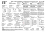
Channel 1: Dip-switch 1 and 2
Channel 2: Dip-switch 3 and 4
Sensitivity level
1 low
(0,64% �f/f)
2
(0,16% �f/f)
3
(0,04% �f/f)
4 high
(0,01% �f/f)
a) Single vehicle
Dip-switch 8
1
2
1
2
1
2
Relay 1:
Signal ON
1
2
Relay 1:
Signal remains
1
2
Relay 1:
Signal OFF
1
2
1
2
1
2
Relay 1:
Signal ON
1
2
Relay 1:
Signal remains
1
2
Relay 1:
Signal remains
1
2
Relay 1:
Signal OFF
1
2
Relay 1:
Signal ON
Direction presence
signal
1
2
Relay 1:
Signal remains
Direction pulse
signal
1
2
Relay 1:
Signal OFF
Fig.1
Frequency
Dip-switch 5
Low
High
Fig.2
Relay 1:
Pulse
b) Column traffic
Hold time
Dip-switch 6
5 minutes
Infinite
Fig.3
Dip-switch 7
Dip-switch 8
Output mode
Both channels:
Presence output
Chan.1: Presence output
Chan.2: Pulse when loop
gets free
Fig.4
Dip-switch 7
Dip-switch 8
Output mode
1
2
1
2
1
2
Relay 1:
Signal ON
1
2
Relay 1:
Signal OFF
1
2
Relay operating principle
I*)
Relay 1:
Pulse
c) Reversing vehicle
Fig.5
Detector state
Relay 1:
Pulse
II
III
IV
Power OFF
Loop free
Relay 1:
Pulse
Output signal
Loop failure
Relay 2:
Pulse
*) Standard configuration
JP4
Close-circuit principle
Changeable by jumper
Fixed by solder link
Optionally setting (change solder link)
3
2-3
2
Open-circuit principle
JP4
Make contact
1-2
Relay
1
2-3
Relay
3
Break contact
2
Close-circuit principle
1-2
JP2
2-3
JP3
Open-circuit principle
3
1-2
2
Make contact
1
JP2
2
Break contact
2-3
JP1
JP3
1-2
Board
1
1
Relay
function
3
JP1
Position
2
Jumper
1
Relay
Fig.6
Fig.7
5