1
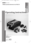
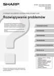
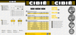
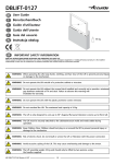
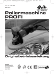
77084 Bed.:Lay
01.03.2011
14:26 Uhr
Seite 1
77 084
D LED-Tagfahr-/ Positionslicht
LED vehicle daylight / marker light
F Feu de jour/feu de position LED
I Luce di marcia diurna / di posizione a LED
Światła LED do jazdy dziennej/pozycyjne
Gebrauchsanweisung
Hergestellt für:
INTER-UNION Technohandel GmbH
Klaus-von-Klitzing-Straße 2
76829 Landau · Germany
www.inter-union.de
Dystrybutor:
INTERTEC POLSKA Sp. z o.o.
05-830 Nadarzyn, Stara Wieś ul. Grodziska 22
tel: 22 738-64-60, fax: 22 738-64-68, 69
www.intertec-polska.pl
E-mail: [email protected]
E4
Modell: JS-09308 · Stand: 02/2011 · Version: 1.1
20
PAP
Instruction manual
Mode d’emploi
Istruzioni d’uso
Instrukcja obsługi
77084 Bed.:Lay
01.03.2011
14:26 Uhr
Seite 2
D
Bedienungs- und Sicherheitshinweise
Willkommen
Sicherheitshinweis
Technische Daten:
Gebrauchsanweisung
Achtung:
Dieses LED Tagfahr-/Positionslicht von UNITEC ist sehr sorgfältig konstruiert und hergestellt
worden, damit es immer zuverlässig arbeitet. Bevor Sie das LED Tag-/Positionsfahrlicht benutzen,
lesen Sie bitte diese Hinweise genau durch; Sie erfahren darin alles, was Sie wissen und beachten müssen, damit das LED Tag-/Positionsfahrlicht Ihnen viele Jahre lang gute Dienste leistet.
Bewahren Sie diese Hinweise für spätere Anfragen bitte auf.
Bitte die zulässige Montagebreite und -höhe beachten
Abb. 1
(siehe Plan). Der Abstand zwischen den beiden LED Tagfahr/Positionslichtern muss mindestens 600 mm betragen. Der
maximale Abstand von 400 mm vom Ende der LED Tagfahr/Positionslichter bis zur Außenkante des Kotflügels muss
eingehalten werden. Der Mindestabstand des LED Tagfahr/Positionslichts zur Fahrbahn muss mind. 250 mm betragen.
Die max. Montagehöhe beträgt 1500 mm zur Fahrbahn. Beide
LED Tagfahr-/Positionslichter müssen die gleichen Abstände
zur Außenkante des Fahrzeugs und Boden einhalten.
Bitte die Zündung und den Motor während den Arbeiten an der Elektrik ausschalten, da es
ansonsten zu einem Kurzschluss oder auch zu Verletzungen kommen kann. Sollten während der
Montage Unklarheiten oder Bedenken hinsichtlich der persönlichen Fähigkeiten auftreten, wenden Sie sich bitte an eine Fachwerkstatt.
Abb. 2
Geeignet für 12V und 24V DC Betrieb.
LED-Leistung ca. 6 Watt
gelbes Kabel
Vor Montage des LED Tagfahr-/Positionslichts entfernen Sie bitte die Kabel (weiß und schwarz) von
den Kabeln der Batterieboxen. Diese sind verbunden wegen der sogenannten Testfunktion.
schwarzes Kabel
weißes Kabel
Nach Montage des LED Tagfahr-/Positionslichts an
entsprechender Stelle Ihres Fahrzeuges, nach den
Vorgaben aus Abbildung 1, folgt nun der Anschluss
an der Bordelektronik. Hierzu beachten Sie bitte
den angegebenen Schaltplan (Abbildung 2).
1. Befestigen Sie beide gelben Leitungen an beiden LED Tagfahr-/Positionslichtern sowie an beiden + (plus) Kabeln des Standlichtes.
2. Verbinden Sie beide LED Tagfahr-/Positionslichter mit dem schwarzen Kabel, sowie mit einer
Leitung des – (minus) Pol der Fahrzeugbatterie, oder einem geeigneten Massepunkt Ihres
Fahrzeugs (Karosserie).
3. Verbinden Sie als letzten Schritt, das weiße Kabel mit den LED Tagfahr-/Positionslichtern
sowie dem + (plus) Pol Ihrer Fahrzeugbatterie.
4. Setzen Sie die serienmäßigen vorderen Standlichter / Positionslichter ihres Fahrzeuges
dauerhaft außer Funktion.
5. Beim erstmaligen Anschluss an die Batterie erlischt das LED-Tagfahr/Positionslicht nach einigen Sekunden. Dies ist völlig normal.
Bitte beachten Sie, dass das LED-Tagfahr-/Positionslicht nur bei laufendem Motor einwandfrei
funktioniert. Bei ausgeschaltetem Motor funktioniert nur das abgedimmte Positionslicht, bei entsprechender Schalterstellung im Fahrzeug (Standlichtfunktion).
Gegebenenfalls kann die Installation des LED Tagfahr-/Positionslichts zu Störungen bzw. Fehlermeldungen der Bordüberwachung (Bordcomputer) führen. In diesem Fall suchen Sie bitte eine
Fachwerkstatt auf. Diese kann den Fehler dann ggf. ausschalten bzw. beheben.
Nach der erfolgreichen Installation, sollte das LED Tagfahr-/Positionslicht bei Einschalten des
Motors funktionieren. Im Nachgang bitten wir Sie noch zu prüfen, ob die LED-Tagfahrleuchte bei
Einschalten des herkömmlichen Abblendlichts, sich in den Positionslicht-Modus schaltet. D.h. die
Leuchtkraft der LED´s wird etwas schwächer werden.
Bei neuen Fahrzeugen u.a. Audi, VW ab Baujahr 2006 wurde die Stromstärke, welche an die
Leuchten geht, etwas geschwächt, um die Lebensdauer der Leuchtmittel zu verlängern. Dies
kann dazu führen, dass die LED-Leuchten nicht ordnungsgemäß auf Positionslicht umschalten
(Dimmung) bei Einschalten des herkömmlichen Abblendlichts. Um die Funktion dennoch nutzen
zu können, sollten Sie anhand Abb. 3 herkömmliche 12 V / 10 A-Relais installieren, welche nicht
im Lieferumfang enthalten sind.
Abb. 3
Plus-Kabel Parkleuchte
(links)
Masse
Plus-Kabel Parkleuchte
(rechts)
Masse
gelbes Kabel
gelbes Kabel
Leuchte
Leuchte
(rechts)
(links)
schwarzes Kabel schwarzes Kabel
weißes Kabel
weißes Kabel
Die Kabel sind nicht im
Lieferumfang enthalten
Entsorgungshinweis
Reinigung
Entsorgen Sie dieses Produkt nach der Lebensdauer nicht im Hausmüll, sondern führen Sie dieses Produkt einer fachgerechten Entsorgung zu. Ihr Öffentlicher Entsorgungsträger hilft Ihnen
gerne weiter.
Verwenden Sie zur Reinigung nur Wasser, milde Seife und ein weiches Tuch. Verwenden Sie
keine Lösungsmittel wie Spiritus oder Benzin. Lösungsmittel können das Material angreifen.
77084 Bed.:Lay
01.03.2011
14:26 Uhr
Seite 3
GB
Operating and safety instructions
These LED vehicle daylight / marker lights from UNITEC have been carefully designed and manufactured to ensure all-round reliability. Before using your LED vehicle daylight / marker light,
please read carefully through these instructions, which contain all you need to know in order to
ensure that your LED vehicle daylight/marker lights give you many years of reliable service.
Please keep the instructions in a safe place for future reference.
Welcome
Please observe the permitted installation-width and height
limits (see plan). The two LED lamps must be fitted at least
600 mm apart from one another. Be sure to observe the
maximum distance of 400 mm between the side of the
LED lamp and the outer edge of the vehicle’s wing. The
minimum distance between the LED lamp and the roadway
is 250 mm. The maximum installation height with respect to
the roadway is 1500 mm. Both lamps must be at the same
distance from the roadway and their respective sides of
the vehicle.
Note on safety
Fig. 1
In order to prevent short circuits and possible injuries, stop the engine and switch off the
ignition before carrying out electrical work of any kind. If you are in any doubt as to your level of
knowledge or skill, please contact a specialist installation workshop.
Suitable for 12V DC and 24V DC systems. LED
power capacity approx. 6 watts
Technical specifications
Fig. 2
LED vehicle daylight / marker lights offer the extra
safety that comes with increased visibility in traffic.
Function
yellow wire
Fitting instructions
Disconnect the wires (coloured white and black
respectively) from the battery-box wires before
installing the LED vehicle daylight / marker lights.
These are used to carry out the test function.
black wire
white wire
Once you have installed your LED vehicle
daylight/marker lights in their corresponding positions on the vehicle, following the instructions
shown in fig. 1, you can connect them to the onboard electronic system. Please refer to the circuit diagram shown above (fig. 2) when doing so.
1. Connect the yellow wire to both lights and one wire to the + (plus) pole lead of the existing
sidelight.
2. Connect both LED vehicle daylight / marker lights to the black wire, and also to a wire leading
from the - (negative) pole of the vehicle’s battery, or to a suitable earthing (ground) point on
the body.
3. To conclude the operation, connect the white lead to the lights and to the + (plus) terminal of
your vehicle’s ignition system.
4. Permanently deactivate your vehicle’s standard front parking lights/marker lights.
In principle the installation of the LED vehicle daylight/marker light may cause faults or error
messages in the onboard monitoring system (onboard computer). In this event contact a specialist garage. It may be able to rectify or eliminate the fault. You can also read or delete this fault
with an “OBD II scanner”.
Once installation is complete, the LED vehicle daylight/marker light should work when the engine
is switched on. Then please also check that the LED vehicle daylight light switches to the marker
light mode when the normal headlights are switched on i.e. the brilliance of the LEDs will be
somewhat reduced.
In new vehicles, including Audi and VW from build year 2006, the current strength going to the
lamps was somewhat reduced into order to prolong the service life of the lights. In consequence,
it may be that the LED lights do not correctly switch to position light (dimming) when the conventional headlights are switched on. In order to continue using the function, you should install a
conventional 12 V / 10 A relay as shown in fig. 3; this relay is not included in the scope of delivery.
Attention:
Fig. 3
positive wire of parking light
(left side)
ground
positive wire of parking light
(right side)
ground
yellow wire
yellow wire
lamp
lamp
(left side)
(right side)
black wire
white wire
black wire
white wire
The cables are not included
in the scope of deliverie
Do not dispose of this product in the domestic waste at the end of its useful life. You can find out
more details from your official disposal body. Do not dispose of the battery in the domestic waste
but take it to the special waste disposal point.
Disposal instructions
77084 Bed.:Lay
01.03.2011
14:26 Uhr
Seite 4
F
Instructions d'utilisation et consignes de
sécurité
Bienvenue
Instructions de sécurité
Données techniques:
Fonction:
Instructions d’utilisation:
Attention :
Ces feu de jour/feu de position LED d’UNITEC ont été conçus et fabriqués avec le plus grand soin
pour permettre un fonctionnement fiable à tout moment. Veuillez lire ces instructions attentivement avant d’utiliser les feux de jour/feu de position LED ; vous y apprendrez tout ce que vous
avez besoin de savoir et de respecter pour que les feux de jour/feu de position LED vous rendent
de bons services pendant de nombreuses années. Veuillez conserver ces instructions pour vous
y référer ultérieurement.
Fig. 1
Veuillez respecter la largeur et la hauteur admissibles pour
le montage (voir plan). La distance entre les deux phares
LED doit être d’au moins 600 mm. La distance maximale de
400 mm entre le bord du phare LED et l'extrémité hors tout
de l’aile du véhicule est à respecter. La distance minimale
entre le phare LED et la chaussée doit être de 250 mm. La
hauteur de montage maximale est de 1500 mm par rapport
à la chaussée. Les deux phares doivent avoir la même
distance par rapport à l'extrémité hors tout du véhicule et
par rapport au sol.
Durant l’intervention sur les pièces électriques, veuillez maintenir l’allumage et le moteur éteints,
pour éviter tout risque de court-circuit et de blessures. Si vous avez des doutes ou incertitudes
durant le montage concernant vos facultés personnelles, veuillez vous adresser à un garage
professionnel.
Fig. 2
Conviennent pour un fonctionnement 12V et 24V DC. Puissance LED env. 6 watts
fil jaune
Les feux de jour/feu de position LED vous procurent
davantage de sécurité en offrant une meilleure visibilité dans la circulation routière.
Avant de monter les feux de jour/feu de position
fil noir
fil blanc
LED, veuillez éloigner les fils (blanc et noir) des
câbles de la batterie. Ceux-ci sont reliés en raison
de la fonction de test.
Une fois les feux de jour/feu de position LED montés sur votre véhicule, suivant les indications de la
figure 1, il faut les brancher sur l’électronique
embarquée. Pour ce faire, veuillez respecter le plan de câblage ci-dessous (figure 2).
1. Fixez maintenant le fil jaune aux deux feux et un fil au câble + (positif) du feu de position.
2. Raccordez les deux feux de jour/feu de position LED au câble noir et à un câble du pôle (négatif) de la batterie du véhicule, ou bien à un point de masse approprié de votre véhicule
(carrosserie).
3. En dernier, raccordez le câble blanc avec les feux et avec le + (positif) après contact de votre
véhicule. Si vous ne savez pas où trouver le positif après contact dans votre véhicule, veuillez
vous adresser à un garage professionnel.
4. Mettez les feux de position avant montés de série sur votre véhicule définitivement hors service.
En principe, l’installation du feu de jour/feu de position LED peut engendrer des perturbations ou
des messages d’erreur au niveau de la surveillance embarquée (ordinateur de bord). Dans ce
cas, veuillez vous adressez à un atelier spécialisé. Ce dernier est en mesure d'effacer l’erreur ou
de la résoudre. Au besoin, vous pouvez également lire et effacer cette erreur au moyen d’un
scanner OBD II.
Après une installation réussie, le feu de jour/feu de position LED doit fonctionner lorsque vous
mettez le moteur en marche. A posteriori, veuillez également vérifier si le feu de jour LED passe
en mode feu de position lorsque vous allumez les feux de croisement conventionnels, c'est-àdire si l'intensité lumineuse des LED s'affaiblit quelque peu.
Sur les nouveaux véhicules à partir de l’année de construction 2006, et notamment Audi et VW,
l’intensité de courant destinée aux phares a été quelque peu diminuée afin de prolonger la durée
de vie des ampoules. Il est possible que les lampes LED de ce fait ne passent pas correctement
en feux de position (variation) lorsqu’on allume les feux de croisement. Afin de pouvoir cependant utiliser la fonction, il vous est recommandé d’installer comme l’indique les figures ci-contre
un relais traditionnel 12 V/10 A qui n’est pas compris dans les fournitures (Fig. 3).
Fig. 3
Câble positif du feu de position
(côté gauche)
Terre
Câble positif du feu de position
(côté droit)
Terre
Fil jaune
Fil jaune
Phare
Phare
(côté gauche)
(côté droit)
Fil noir
Fil noir
Fil blanc
Fil blanc
Les câbles ne sont pas
compris dans les fournitures
Instructions pour
l’élimination
À la fin de la durée de vie de ce produit, ne l‘éliminez pas avec les ordures ménagères.
Pour en savoir plus, merci de vous adresser à l’organisme de droit public compétent. N’éliminez
pas l'accumulateur avec les ordures ménagères mais faites-le parvenir à un point de collecte de
déchets toxiques.
77084 Bed.:Lay
01.03.2011
14:26 Uhr
Seite 5
I
Istruzioni per l’uso e avvertenze sulla
sicurezza
I presenti luce di marcia diurna / di posizione a LED di UNITEC sono stati progettati e prodotti con
la massima accuratezza, affinché funzionino sempre con la dovuta affidabilità. Prima di utilizzarli,
si raccomanda di leggere attentamente ed osservare le istruzioni a seguito riportate, per restare
soddisfatti lunghi anni del vostro acquisto. Conservare le presenti istruzioni per una successiva
consultazione.
Fig. 1
Rispettare la larghezza ed altezza di montaggio ammessa
(v. schizzo). La distanza tra i due fari a LED deve ammontare ad almeno 600 mm. Osservare assolutamente anche la
distanza massima di 400 mm dall’estremità del faro a LED
allo spigolo esterno del parafango. La distanza minima tra il
faro a LED e la corsia deve ammontare a 250 mm. L’altezza di
montaggio massima rispetto alla corsia ammonta a 1500
mm. Entrambi i fari devono presentare le stesse distanze
rispetto allo spigolo esterno del parafango e al suolo.
Si raccomanda di spegnere l’accensione ed il motore durante i lavori sull’impianto elettrico,
perché altrimenti potrebbe insorgere un corto circuito o anche pericolo di lesioni. Se durante il
montaggio dovessero manifestarsi incertezze o dubbi a riguardo delle proprie capacità, è consigliabile rivolgersi ad un’officina specializzata.
Fig. 2
Indicato per il funzionamento a corrente continua
DC 12V e 24V . Potenza LED ca. 6 Watt
cavo giallo
Il luce di marcia diurna / di posizione a LED vi offrono maggior sicurezza grazie ad una migliore visibilità nella circolazione stradale.
Prima di montare i luce di marcia diurna / di posicavo nero
cavo bianco
zione a LED, rimuovere i cavi (bianco e nero) dai
cavi delle cassette portabatteria. Questi sono
collegati per via della cosiddetta funzione di prova.
Dopo aver sistemato in base alla Fig. 1 i luce di
marcia diurna / di posizione a LED sui relativi punti
della vettura, si effettua l’allacciamento all’impianto
elettronico di bordo. A tal fine osservare lo schema dei collegamenti sottostante (Fig. 2).
1. Fissare ora il conduttore giallo su entrambi i fari, nonché un conduttore sul cavo + (positivo)
del fanale di posizione.
2. Collegare entrambi i luce di marcia diurna / di posizione a LED al cavo nero, nonché ad un
conduttore del polo - (negativo) della batteria auto, o ad un punto massa idoneo della vostra
vettura (carrozzeria).
3. Per ultimo collegare il cavo bianco ai fari nonché al polo + (positivo) del blocchetto
d’accensione auto. Se non sapete come trovare il polo positivo del blocchetto d’accensione,
è consigliabile rivolgervi ad un’officina specializzata.
4. Mettere permanentemente fuori servizio le luci di posizione anteriori di serie del proprio veicolo.
L'installazione della luce di marcia diurna / di posizione a LED può disturbare il sistema di monitoraggio di bordo (computer di bordo) o causare messaggi di errore. In questo caso rivolgersi a
un'officina specializzata che potrà eliminare il disturbo. Eventualmente è possibile selezionare e
cancellare l'errore anche tramite un cosiddetto scanner OBD II.
Se l'installazione è stata eseguita correttamente, all'accensione del motore la luce di marcia
diurna / di posizione a LED dovrebbe funzionare. Verificare poi se, all'accensione degli anabbaglianti tradizionali, la luce di marcia diurna a LED si commuta nella modalità luce di posizione, ovvero se la luminosità dei LED diminuisce.
A partire dall'anno di costruzione 2006 nei nuovi veicoli, tra cui Audi e VW, l'intensità della corrente diretta alle luci è stata leggermente diminuita per allungare la vita utile delle sorgenti luminose. Di conseguenza, all'accensione degli anabbaglianti tradizionali, le luci a LED potrebbero
non commutarsi regolarmente in luci di posizione (variazione dell'intensità luminosa). Per utilizzare comunque la funzione è possibile installare un relè tradizionale da 12 V / 10 A, non compreso
nella fornitura, seguendo le illustrazioni riportate accanto (Fig. 3).
Benvenuti
Norme di sicurezza
Dati tecnici:
Finalità:
Istruzioni d’uso:
Attenzione:
Fig. 3
Cavo positivo della luce di posizione
(lato sinistro)
Terra
Cavo positivo della luce di posizione
(lato destro)
Terra
Cavo giallo
Cavo giallo
Faro
Faro
(lato sinistro)
(lato destro)
Cavo nero
Cavo bianco
Cavo nero
Cavo bianco
I cavi non sono
compresi nella fornitura
Al termine della sua vita non smaltire questo prodotto tra i rifiuti domestici. Per maggiori informazioni rivolgersi al proprio gestore pubblico di rifiuti. Non smaltire la batteria tra i rifiuti domestici,
bensì tra i rifiuti speciali.
Istruzioni per lo smaltimento
77084 Bed.:Lay
01.03.2011
14:26 Uhr
Seite 6
PL
Instrukcja obsługi oraz wskazówki
Witamy
Wskazówka
bezpieczeństwa
Dane techniczne:
Funkcja:
Instrukcja obsługi:
Uwaga:
Światła LED do jazdy dziennej/pozycyjne firmy UNITEC zostały skonstruowane i wyprodukowane
z zachowaniem najwyższej staranności, tak by zapewnić ich niezawodne działanie. Przed użyciem
świateł LED do jazdy dziennej/pozycyjne należy uważnie przeczytać następujące wskazówki.
Dowiedzą się Państwo z nich wszystkiego, co należy wiedzieć i czego przestrzegać, aby światła
LED do jazdy dziennej/pozycyjne niezawodnie służyły przez wiele lat. Należy zachować te
wskazówki na wypadek późniejszych zapytań.
Należy przestrzegać dopuszczalnej szerokości i
Ilu. 1
wysokości montażu (patrz układ). Odstęp pomiędzy
dwoma reflektorami LED powinien wynosić przynajmniej
600 mm. Należy zachować maksymalny odstęp – 400 mm
między końcem reflektora LED a zewnętrzną krawędzią
błotnika. Minimalny odstęp pomiędzy reflektorem LED
a jezdnią powinien wynosić 250 mm. Maksymalna
wysokość montażu wynosi 1500 mm ponad jezdnią.
Odstępy między reflektorami i zewnętrzną krawędzią
pojazdu oraz podłożem powinny w przypadku obu
reflektorów być jednakowe.
Należy wyłączyć zapłon i silnik podczas prac przy instalacji elektrycznej, ponieważ może dojść do
zwarcia a także obrażeń ciała. Jeśli w trakcie montażu pojawią się niejasności lub wątpliwości
dotyczące własnych umiejętności, należy zwrócić
się do specjalistycznego warsztatu.
Ilu. 2
Przeznaczone do napięcia 12 V i 24 V zasilanie
kable żółty
DC , moc LED ok. 6 W
Światła LED do jazdy dziennej/pozycyjne zapewniają Państwu większe bezpieczeństwo dzięki lepszej
widoczności w ruchu drogowym.
kable czarnego
kable białego
Przed montażem lamp do jazdy dziennej z diodami
LED należy rozdzielić kable (koloru białego i czarnego) od kabli skrzynki akumulatora. Są one ze sobą
połączone z powodu tzw. funkcji testowej.
Po montażu lampy LED do jazdy dziennej/pozycyjne
w odpowiednim miejscu pojazdu według wytycznych zamieszczonych na ilustracji nr 1 następuje podłączenie do instalacji elektronicznej pojazdu.
Należy uwzględnić przy tym podany układ połączeń (ilustracja nr 2).
1. Żółty przewód przymocować do obu lamp oraz jeden przewód do kabla o biegunie
+ (dodatnim) świateł postojowych.
2. Połączyć obie lampy LED do jazdy dziennej/pozycyjne za pomocą czarnego kabla oraz
przewodu o biegunie – (ujemnym) akumulatora pojazdu lub z odpowiednim punktem masy
w pojeździe (karoseria).
3. Na koniec podłączyć biały kabel do lamp oraz do + (plusa) załączanego plusa pojazdu. Jeśli
nie wiedzą Państwo, gdzie w pojeździe znajduje się załączany plus, należy zwrócić się do
specjalistycznego warsztatu.
4. Wyłączyć na stałe seryjne przednie światła postojowe/światła pozycyjne pojazdu.
Zasadniczo instalacja świateł LED do jazdy dziennej/postojowych może prowadzić do zakłóceń
lub komunikatów o błędzie w komputerze pokładowym. W takim wypadku należy zgłosić się do
specjalistycznego warsztatu, gdzie komunikat i błąd zostaną usunięte. Błąd można wyszukać i
usunąć także z użyciem skanera diagnostycznego OBD II.
Po udanej instalacji światła LED do jazdy dziennej/pozycyjne powinny zacząć działać w momencie uruchomienia silnika. Dodatkowo należy jeszcze sprawdzić, czy światła LED do jazdy dziennej
w momencie włączenia zwykłych świateł mijania przechodzą w tryb świateł pozycyjnych, tzn. czy
zmniejsza się siła światła LED.
W nowych pojazdach między innymi marek Audi i VW począwszy od rocznika 2006, aby wydłużyć żywotność opraw oświetleniowych, zmniejszono nieco moc zasilającego je prądu. Może to doprowadzić do
tego, że przy włączaniu tradycyjnych świateł mijania, oprawy LED mogą nie przełączać się poprawnie na
tryb świateł pozycyjnych (ściemnianie). Aby mimo to umożliwić działanie tej funkcji, należy zainstalować,
stosując się do umieszczonych obok rysunków, tradycyjne przekaźniki 12 V / 10 A ((ilustracja nr 3).
Przekaźniki te nie wchodzą w zakres dostawy.
Ilu. 3
Biegun dodatni przewodu światła postojowego
(Strona lewa)
Masa
Biegun dodatni przewodu światła postojowego
(Strona prawa)
Masa
Kable żółty
Kable żółty
Lampa
Lampa
(strona lewa)
(strona prawa)
Kable czarnego
Kable białego
kable czarnego
Kable białego
Kable nie wchodzą w
zakres dostawy
Recykling
W momencie, kiedy urządzenie stanie się bezużyteczne, nie wolno wyrzucać go do pojemników
z domowymi śmieciami, tylko poddać recyklingowi zgodnie z obowiązującymi krajowymi przepisami w tym względzie. Akumulatory muszą zostać poddane recyklingowi w miejscach do tego
przenaczonych.