1
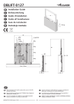
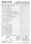
77087 Bed_110922:Lay
22.09.2011
11:24 Uhr
Seite 2
77 087
PL
Instrukcja obsługi oraz wskazówki
Witamy
Wskazówka
bezpieczeństwa
Światła pozycyjne LED firmy UNITEC zostały skonstruowane i wyprodukowane z zachowaniem
najwyższej staranności, tak by zapewnić ich niezawodne działanie. Przed użyciem świateł
pozycyjne LED należy uważnie przeczytać następujące wskazówki. Dowiedzą się Państwo z nich
wszystkiego, co należy wiedzieć i czego przestrzegać, aby światła pozycyjne LED niezawodnie
służyły przez wiele lat. Należy zachować te wskazówki na wypadek późniejszych zapytań.
Należy przestrzegać dopuszczalnej szerokości i wysokości
montażu (patrz układ). Odstęp pomiędzy dwoma reflektorami LED powinien wynosić przynajmniej 600 mm. Należy
zachować maksymalny odstęp – 400 mm między końcem
reflektora LED a zewnętrzną krawędzią błotnika. Minimalny
odstęp pomiędzy reflektorem LED a jezdnią powinien
wynosić 350 mm. Maksymalna wysokość montażu wynosi
1500 mm ponad jezdnią. Odstępy między reflektorami i
zewnętrzną krawędzią pojazdu oraz podłożem powinny w
przypadku obu reflektorów być jednakowe.
D
F
I
LED-Positionslicht
LED marker light
Feu de position LED
Luce di posizione a LED
Światła pozycyjne LED
Gebrauchsanweisung
• Wyłączyć zapłon oraz silnik podczas prac przy pojeździe.
• Zadbać o to, by z położonymi przewodami nie stykały się obracające się części oraz o to, by kable
nie zostały uszkodzone przez wpływ wysokiej temperatury.
• W razie uszkodzenia wbudowanego bezpiecznika topikowego zastąpić go bezpiecznikiem o takich
samych parametrach.
• Wyłączenie seryjnych świateł postojowych/pozycyjnych może wywołać komunikaty błędów w
Państwa pojeździe (OBD On Bord Diagnose). W takim przypadku należy zwrócić się do specjalistycznego warsztatu samochodowego.
• Jeżeli podczas montażu nasuną się wątpliwości dotyczących własnych umiejętności, należy
zwrócić się do specjalistycznego warsztatu samochodowego.
Instrukcja obsługi:
1. Wyznaczyć idealną pozycję do zabudowy świateł pozycyjnych LED na podstawie przedstawionego
powyżej schematu zabudowy.
2. Poprowadzić kable podłączeniowe przy wcześniej wybranych pozycjach zabudowy.
3. Połączyć światła pozycyjne za pomocą kabla podłączeniowego.
4. Przymocować światła pozycyjne do Państwa pojazdu za pomocą załączonego materiału
mocującego.
5. Podłączyć czerwony kabel do światła pozycyjnego/postojowego będącego na wyposażeniu
pojazdu.
6. Podłączyć czarny kabel do masy/biegun ujemny pojazdu.
7. Wyłączyć na stałe seryjne przednie światła postojowe/światła pozycyjne pojazdu.
czerwony
Schemat połączeń
⊕
czarny
⊖
Dane techniczne:
Recykling
Czyszczenie:
• nadaje się do 12 V
• pobór mocy 2 x 1,6 W
• Wymiary: szer. 13 cm x gł. 4 cm x wys. 2 cm
W momencie, kiedy urządzenie stanie się bezużyteczne, nie wolno wyrzucać go do pojemników
z domowymi śmieciami, tylko poddać recyklingowi zgodnie z obowiązującymi krajowymi
przepisami w tym względzie. Akumulatory muszą zostać poddane recyklingowi w miejscach do
tego przenaczonych.
Do czyszczenia używać tylko wody, delikatnego mydła i miękkiej ściereczki. Nie stosować
rozpuszczalników takich jak spirytus czy benzyna. Rozpuszczalniki mogą uszkodzić materiał.
Hergestellt für:
INTER-UNION
Technohandel GmbH
Klaus-von-Klitzing-Str. 2
76829 Landau · Germany
www.inter-union.de
Dystrybutor:
INTERTEC POLSKA Sp. z o.o.
05-830 Nadarzyn,
Stara Wieś ul. Grodziska 22
tel: 22 738-64-60,
fax: 22 738-64-68, 69
www.intertec-polska.pl
E-mail: [email protected]
Modell: AZ-80990 · Stand: 09/2011 · Version: 1.1
E4
21
PAP
Instruction manual
Mode d’emploi
Istruzioni d’uso
Instrukcja obsługi
77087 Bed_110922:Lay
22.09.2011
11:24 Uhr
Seite 4
D
GB
Bedienungs- und Sicherheitshinweise
Operating and safety instructions
Willkommen Dieses LED Positionsfahrlicht von UNITEC ist sehr sorgfältig konstruiert und hergestellt worden,
damit es immer zuverlässig arbeitet. Bevor Sie das LED Positionsfahrlicht benutzen, lesen Sie
bitte diese Hinweise genau durch; Sie erfahren darin alles, was Sie wissen und beachten
müssen, damit das LED Positionsfahrlicht Ihnen viele Jahre lang gute Dienste leistet. Bewahren
Sie diese Hinweise für spätere Anfragen bitte auf.
Sicherheitshinweis Bitte die zulässige Montagebreite und -höhe beachten
(siehe Plan). Der Abstand zwischen den beiden LED Positionsfahrleuchten muss mindestens 600 mm betragen. Der
maximale Abstand von 400 mm vom Ende der LED Positionsfahrleuchte bis zur Außenkante des Kotflügels muss eingehalten werden. Der Mindestabstand von der LED Positionsfahrleuchte zur Fahrbahn muss mind. 350 mm betragen. Die
max. Montagehöhe beträgt 1500 mm zur Fahrbahn. Beide
LED Positionsfahrleuchten müssen die gleichen Abstände
zur Außenkante des Fahrzeugs und Boden einhalten.
• Zündung und Motor während der Arbeiten am Fahrzeug ausschalten.
• Tragen Sie Sorge das keine rotierenden Teile mit den verlegten Kabeln in Verbindung kommen
können oder die Kabel durch Hitzeeinfluss beschädigt werden können.
• Sollte die eingebaute Schmelzsicherung beschädigt werden ersetzen Sie diese nur durch eine
Sicherung mit dem gleichen Sicherungswert.
• Die Außerkraftsetzung der serienmäßigen Standlichter /Positionslichter kann zu Störungsmeldungen in Ihrem KFZ (OBD On Bord Diagnose) führen, wenden Sie sich im oberen Fall bitte an
eine Fachwerkstatt. Diese Meldung kann mit einem sog. OBD-Scanner ggf. auch selbstständig
ausgelesen und gelöscht werden.
• Sollte während der Montage Unklarheiten oder Bedenken hinsichtlich der persönlichen Fähigkeiten auftreten, wenden Sie sich bitte an eine Fachwerkstatt.
Einbau 1. Bestimmen Sie die ideale Einbauposition für die LED Positionslichter anhand dem oben
abgebildeten Einbauschema.
2. Verlegen Sie die Anschlusskabel an die zuvor ausgewählten Einbaupositionen.
3. Verbinden Sie die Positionslichter mit dem Anschlusskabel.
4. Befestigen Sie die Positionslichter an ihrem Fahrzeug mit dem beiliegenden Befestigungsmaterial.
5. Schließen Sie das rote Kabel an die Stromführung Ihres bestehenden Positions/Standlicht an.
6. Verbinden Sie das schwarze Kabel mit der Masse/ Minuspol ihres Fahrzeuges.
7. Setzen Sie die serienmäßigen vorderen Standlichter / Positionslichter Ihres Fahrzeuges
dauerhaft außer Funktion.
rot
Anschlussschema
schwarz
⊕
These LED marker light from UNITEC have been carefully designed and manufactured to ensure
all-round reliability. Before using your LED marker light, please read carefully through these
instructions, which contain all you need to know in order to ensure that your LED marker light
give you many years of reliable service. Please keep the instructions in a safe place for future
reference.
Welcome
Please observe the permitted installation-width and height
limits (see plan). The two LED lamps must be fitted at least
600 mm apart from one another. Be sure to observe the
maximum distance of 400 mm between the side of the
LED lamp and the outer edge of the vehicle’s wing. The
minimum distance between the LED lamp and the roadway
is 350 mm. The maximum installation height with respect to
the roadway is 1500 mm. Both lamps must be at the same
distance from the roadway and their respective sides of
the vehicle.
Note on safety
• Switch off the ignition and engine while working on the vehicle.
• Make sure that no rotating parts can come into contact with the cables laid and that the cables
cannot be damaged by the effect of heat.
• If the built-in fuse is damaged, only replace it with a fuse of the same fuse rating.
• Deactivating the standard parking lights/marker lights may lead to error messages in your
vehicle (OBD, onboard diagnosis). Please contact a specialist garage.
• If you have doubts or reservations about your own skills during installation, please contact a
specialist garage.
1. Determine the ideal installation position for the LED marker lights on the basis of the installation
diagram above.
2. Lay the connection cable in the installation position previously selected.
3. Connect the marker lights to the connection cable.
4. Fix the marker lights to your vehicle with the attachment equipment supplied.
5. Connect the red cable to your existing marker/parking light.
6. Connect the black cable to your vehicle’s earth/negative pole.
7. Permanently deactivate your vehicle’s standard front parking lights/marker lights.
red
⊕
black
Fitting instructions:
Connection diagram
⊖
⊖
Technische Daten: • Geeignet für 12 Volt
• Leistungsaufnahme 2 x 1,6Watt
• Maße: B 13cm x T 4cm x H 2cm
Entsorgungshinweis Entsorgen Sie dieses Produkt nach der Lebensdauer nicht im Hausmüll, sondern führen Sie
dieses Produkt einer fachgerechten Entsorgung zu. Ihr Öffentlicher Entsorgungsträger hilft Ihnen
gerne weiter.
Reinigung Verwenden Sie zur Reinigung nur Wasser, milde Seife und ein weiches Tuch. Verwenden Sie
keine Lösungsmittel wie Spiritus oder Benzin. Lösungsmittel können das Material angreifen.
• Suitable for 12 Volts
• Power consumption 2 x 1.6 Watt
• Dimensions: W 13 cm x D 4 cm x H 2 cm
Technical specifications
Do not dispose of this product in the domestic waste at the end of its useful life. You can find out
more details from your official disposal body. Do not dispose of the battery in the domestic waste
but take it to the special waste disposal point.
Disposal instructions
For cleaning use only water, mild soap and a soft cloth. Do not use any solvents such as spirit or
petrol. Solvents may corrode the material.
Cleaning
77087 Bed_110922:Lay
22.09.2011
11:24 Uhr
Seite 6
F
Bienvenue
Instructions de sécurité
Instructions d’utilisation:
I
Instructions d'utilisation et consignes de
sécurité
Istruzioni per l’uso e avvertenze sulla
sicurezza
Ces feux de position LED d’UNITEC ont été conçus et fabriqués avec le plus grand soin pour permettre un fonctionnement fiable à tout moment. Veuillez lire ces instructions attentivement avant
d’utiliser les feux de position LED ; vous y apprendrez tout ce que vous avez besoin de savoir et
de respecter pour que les feux de position LED vous rendent de bons services pendant de nombreuses années. Veuillez conserver ces instructions pour vous y référer ultérieurement.
I presenti luce di posizione a LED di UNITEC sono stati progettati e prodotti con la massima
accuratezza, affinché funzionino sempre con la dovuta affidabilità. Prima di utilizzarli, si
raccomanda di leggere attentamente ed osservare le istruzioni a seguito riportate, per restare
soddisfatti lunghi anni del vostro acquisto. Conservare le presenti istruzioni per una successiva
consultazione.
Benvenuti
Veuillez respecter la largeur et la hauteur admissibles pour
le montage (voir plan). La distance entre les deux phares
LED doit être d’au moins 600 mm. La distance maximale de
400 mm entre le bord du phare LED et l'extrémité hors tout
de l’aile du véhicule est à respecter. La distance minimale
entre le phare LED et la chaussée doit être de 350 mm. La
hauteur de montage maximale est de 1500 mm par rapport
à la chaussée. Les deux phares doivent avoir la même
distance par rapport à l'extrémité hors tout du véhicule et
par rapport au sol.
Rispettare la larghezza ed altezza di montaggio ammessa
(v. schizzo). La distanza tra i due fari a LED deve ammontare
ad almeno 600 mm. Osservare assolutamente anche la
distanza massima di 400 mm dall’estremità del faro a LED
allo spigolo esterno del parafango. La distanza minima tra il
faro a LED e la corsia deve ammontare a 350 mm. L’altezza
di montaggio massima rispetto alla corsia ammonta a
1500 mm. Entrambi i fari devono presentare le stesse
distanze rispetto allo spigolo esterno del parafango e al
suolo.
Norme di sicurezza
• Éteindre l’allumage et le moteur durant l’intervention sur le véhicule.
• Veillez à ce qu'aucune pièce en rotation ne puisse toucher les câbles et que les câbles ne
risquent pas d’être endommagés sous l’emprise de la chaleur.
• En cas d’endommagement du fusible intégré, remplacez-le exclusivement par un fusible de
valeur identique.
• Le fait de mettre hors service les feux de position d’origine peut provoquer des messages
d’alerte de votre véhicule (OBD On Bord Diagnostic). Dans ce cas, veuillez vous adresser à un
garage professionnel.
• Si vous avez des doutes ou incertitudes durant le montage concernant vos facultés
personnelles, veuillez vous adresser à un garage professionnel.
• Quando si eseguono i lavori sul veicolo spegnere accensione e motore.
• Assicurarsi che le parti rotanti non possano entrare in contatto con i cavi posati e che i cavi
non possano venire danneggiati da influssi termici.
• Se il fusibile installato dovesse danneggiarsi sostituirlo esclusivamente con un fusibile dello
stesso valore.
• La messa fuori esercizio delle luci di posizione di serie può provocare messaggi di errore nella
propria autovettura (OBD Diagnosi On Bord), in questo caso rivolgersi a un'officina
specializzata.
• Se durante il montaggio dovessero insorgere confusione o dubbi sulle proprie capacità di
installazione, rivolgersi a un'officina specializzata.
1. À l’aide du schéma de montage figurant plus haut, déterminez l’emplacement idéal pour le
montage de vos feux de position LED.
2. Installez les câbles de branchement au niveau des emplacements choisis auparavant.
3. Raccordez les feux de position au câble de branchement.
4. Fixez les feux de position sur votre véhicule à l’aide des éléments de fixation fournis.
5. Branchez le câble rouge à votre feu de position existant.
6. Reliez le câble noir à la masse/ au pôle négatif de vôtre véhicule.
7. Mettez les feux de position avant d’origine durablement hors service.
1. Determinare la posizione ideale di montaggio delle luci di posizione a LED in base allo schema
di montaggio sopra rappresentato.
2. Posare i cavi di collegamento nelle posizioni di montaggio precedentemente selezionate.
3. Collegare le luci di posizione al cavo di collegamento.
4. Fissare le luci di posizione al veicolo mediante il materiale di fissaggio allegato.
5. Collegare il cavo rosso alla luce di posizione esistente.
6. Collegare il cavo nero alla massa/al polo negativo del veicolo.
7. Mettere definitivamente fuori esercizio le luci di posizione anteriori di serie del veicolo.
rouge
Schéma de branchement
⊕
noir
⊖
Données techniques:
Instructions pour
l’élimination
Nettoyage
⊕
rosso
nero
Istruzioni d’uso
Schema di collegamento
⊖
• Convient pour une alimentation 12 volts
• Puissance absorbée 2 x 1,6 watt
• Dimensions: L 13cm x P 4cm x H 2cm
• Idoneo a 12 Volt
• Potenza assorbita 2 x 1,6 Watt
• Dimensioni: L 13 cm x P 4 cm x A 2 cm
Dati tecnici
À la fin de la durée de vie de ce produit, ne l‘éliminez pas avec les ordures ménagères.
Pour en savoir plus, merci de vous adresser à l’organisme de droit public compétent. N’éliminez
pas l'accumulateur avec les ordures ménagères mais faites-le parvenir à un point de collecte de
déchets toxiques.
Al termine della sua vita non smaltire questo prodotto tra i rifiuti domestici. Per maggiori informazioni rivolgersi al proprio gestore pubblico di rifiuti. Non smaltire la batteria tra i rifiuti domestici,
bensì tra i rifiuti speciali.
Istruzioni per lo smaltimento
Ai fini della pulizia usare solo acqua, sapone delicato e un panno morbido. Non utilizzare solventi
come alcol o benzina. I solventi possono aggredire il materiale.
Pukizia
Pour le nettoyage, utilisez uniquement de l’eau, du savon doux et un chiffon doux. N’utilisez pas
de solvant comme le White Spirit ou l'essence. Les solvants peuvent endommager le matériel.