1
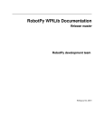
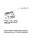
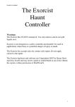
ENSP 4323 et ENSP 4337 N.189 Caméra linéaire Mightex La caméra linéaire Mightex TCE-1304-U est une caméra linéaire monochrome de grande sensibilité qui peut être facilement contrôlée par ordinateur. 1 Logiciel CCDCameraapp Dans ce mode d'emploi, image fait généralement référence à une image unidimensionnelle. 1.1 Mode d'emploi simplié Ce mode d'emploi explique comment obtenir et sauvegarder une image sous forme de chier texte. Les lettres en italique font référence à la gure 1. Des informations plus détaillées sont données au 1.2. La caméra est très sensible : il est conseillé d'utiliser des ltres de densité (de valeur typique 4 pour observer la gure de diraction d'un laser 2 mW). Ouvrir le logiciel CCDCameraapp. Dans la fenêtre Device Selection qui apparaît, sélectionner la caméra et cliquer sur OK. C : choisir Continuous mode. D : choisir la gamme de temps d'exposition. E Choisir le temps d'exposition. F : choisir le répertoire où seront sauvées les images. G : choisir le nom du chier. I : cocher Raw line data. K : cocher Show real time spectrum. A : cliquer sur la èche bleue pour lancer l'acquisition. J : appuyer sur l'icône pour sauver l'image. L'image est sauvée quand il est écrit File Grabbed dans O. 1.2 Signication des commandes et indicateurs A : si ce bouton est une èche bleue, cliquer permet de démarrer l'acquisition. S'il s'agit d'un disque rouge, cliquer permet d'arrêter l'acquisition. B : l'image enregistrée est le résultat d'une moyenne sur le nombre indiqué. 1 sut souvent. C : choix du déclenchement. Choisir Continuous mode pour un déclenchement par ordinateur. D : choix de la gamme de temps d'exposition. E : choix du temps d'exposition. Lorsque la gamme a été modiée, il est conseillé de modier également ce curseur. F : choix du répertoire où seront sauvées les images. G : choix du nom des images. Attention, le nom n'est pas incrémenté automatiquement. Une image est donc remplacée par la nouvelle si le nom n'est pas modié. 1 A B C D E F G H I K J M L N O Figure 1 Fenêtre de contrôle du logiciel CCDCameraapp 2 H : nombre d'images à acquérir. Choisir 1 si le phénomène est indépendant du temps. I : Choix du type d'image. Raw line data permet de sauver les images sous forme de chiers texte (choix à faire par défaut) Combined BMP data sauve en format BMP. J : cliquer sur l'icône pour sauver l'image (ou les images). K : cocher cette case pour que l'image change en temps réel dans la fenêtre L. L'image ne change en temps réel que si le bouton A est le disque rouge (acquisition en cours). L : image sous forme du niveau de gris en fonction de la position. M : indicateur du type de caméra. N : indicateur du taux d'acquisition (en images par seconde). O : indicateur d'activité. File Grabbing ... signie que les images qui seront sauvées sont en cours d'acquisition, File Grabbed que cette acquisition est terminée ou qu'elle n'a pas encore commencée. Il est possible de zoomer sur l'image à l'aide de la souris. 2 Caractéristiques techniques 2.1 Résumé Toshiba TCD1304DG 3 648 Type de capteur CCD Nombre de pixels 200 µm 8 µm 29, 2 mm 350 − 1 000 nm 16 bits (soit 216 = 65 536 niveaux de gris) 0, 1 ms − 6, 5 s 138 scans/s Hauteur du pixel Largeur du pixel Largeur totale du capteur Gamme de longueurs d'onde Profondeur Temps d'exposition Taux d'acquisition maximum La caméra peut être pilotée par un ordinateur dont le système d'exploitation est Windows 2000, XP, Vista, ou Windows 7. La connexion à l'ordinateur se fait à l'aide d'un câble USB 2.0. Aucune alimentation supplémentaire ou carte spécique n'est nécessaire. 2.2 Informations supplémentaires La feuille de données (3 pages, contient notamment la réponse spectrale en page 2) et le manuel d'utilisation (16 pages) sont joins à cette notice. Le logiciel CCDCamerapp peut être téléchargé gratuitement sur le site internet de Mightex : http://www.mightexsystems.com/ en eectuant une recherche avec le nom de la caméra (TCE-1304-U). Des pilotes en C++ et pour Labview sont également disponibles. 3 USB 2.0 3648-Pixel 16bit CCD Line Camera with External Trigger (Part Numbers: TCE-1304-U, TCE-1304-UW ) FEATURES USB2.0 interface No external power supply required Optical integration time adjustable from 100μs to 6.5s 3648 pixel silicon linear CCD array 8μm x 200μm pixel size 16-Bit A/D converter for high intensity resolution Scan rate up to 138 scans/ second External trigger capability 4 GPIOs SDK for user applications Demo software with GUI PRODUCT DESCRIPTION Mightex’s TCE-1304-U line camera is a cost-effective high-performance B/W enclosed line camera, based on a single-line, 3648-pixel CCD chip with USB2.0 (480 Mb/s) interface. CCD line cameras have several advantages over their area-array counterparts, including high optical linear resolution that allows systems developers to use the cameras to capture two-dimensional (2-D) images by moving the object or the CCD perpendicularly to the scan line. TCE-1304-U is a compact line-scan camera ideal for a variety of OEM applications such as industry process control, optical spectroscopy and bio-medical imaging etc. Setting up the TCE-1304-U line camera is very easy: one simply needs to install the camera’s application software into any PC, and then connect the line camera to the PC using a USB cable. There is no need to install a DAC card or to use an external power supply. TCE-1304-UW camera is the window-less version of TCE-1304-U, with the glass window removed from the image sensor. Therefore, the former is more sensitive to UV and is more suitable for applications that involve coherent light sources. PERFORMANCE SPECIFICATIONS Parameters CCD APPLICATIONS Industrial Process Control Optical Spectroscopy Number of pixels Pixel size Spectral range Pixel output clock TCE-1304-U and TCE-1304-UW Unit Toshiba TCD1304DG 3648 pixels 8 x 200 μm TCE-1304-U: 350 to 1000 TCE-1304-UW: 200 to 1000 nm 0.5 MHz 4 frames ADC resolution 16 bits External trigger Yes Data storage on camera Exposure time range Number of GPIOs Frame rate Host interface 0.1 ~ 6,500 ms 4 programmable I/O’s 138 scans/second* USB2.0 * Frame Rate is dependent on exposure time. When exposure time is set to 0.1 ms, the camera can achieve 138 scans/second. SDK Features Operation Systems Windows 2000, XP, Vista and Windows 7 Minimum Requirement RAM > 64M, hard disk space used > 10M USB Port Multiple Cameras Device Driver Demo Application Library Files Example Codes Frame Attributes* 2.0 Supported Yes Yes Yes (DLL files and static library file) Yes (VC++ and Delphi) Exposure Time, Time Stamp, Trigger Event Count, Over-Exposure Detection. * SDK will provide call back, which will send user frame data and the related attributes of the frame. The attributes include: Exposure Time, Time Stamp, Trigger Event Count and Over-Exposure Flag. Mightex Systems, 2343 Brimley Road, Suite 868, Toronto, Ontario M1S 3L6, Canada Tel: 1-416-840-4991 or 1-925-218-1885, Fax: 1-416-840-6541, Email: [email protected] www.mightex.com or www.mightexsystems.com Mightex Simply Brighter USB 2.0 3648-Pixel 16bit CCD Line Camera with External Trigger (Part Numbers: TCE-1304-U, TCE-1304-UW ) SPECTRAL RESPONSE (for TCE-1304-U Only) OPERATION CONDITION Operating Temperature Range -10°C ~ 50°C Relative Humidity, Non-condensing 5% ~ 95% EXAMPLE OF GRAPHICAL USER INTERFACE Mightex Systems, 2343 Brimley Road, Suite 868, Toronto, Ontario M1S 3L6, Canada Tel: 1-416-840-4991 or 1-925-218-1885, Fax: 1-416-840-6541, Email: [email protected] www.mightex.com or www.mightexsystems.com Mightex Simply Brighter USB 2.0 3648-Pixel 16bit CCD Line Camera with External Trigger (Part Numbers: TCE-1304-U, TCE-1304-UW ) MECHANICAL DIMENSIONS Length x Width x Height: 78(mm) x 42(mm) x 57(mm) Weight: 200g With a world-class OEM design team, Mightex offers a broad range of customized solutions in order to meet individual customer’s unique requirements. Please call 1-416-840 4991 or email [email protected] for details. Mightex Systems, 2343 Brimley Road, Suite 868, Toronto, Ontario M1S 3L6, Canada Tel: 1-416-840-4991 or 1-925-218-1885, Fax: 1-416-840-6541, Email: [email protected] www.mightex.com or www.mightexsystems.com Mightex Simply Brighter (In Canada) 2343 Brimley Road Suite 868 Toronto, Ontario M1S 3L6 CANADA Tel: 1-416-840 4991 Fax: 1-416-840 6541 Simply Brighter (In US) 1032 Serpentine Lane Suite 113 Pleasanton, CA 94566 USA Tel: 1-925-218 1885 Email: [email protected] Mightex CCD Line Camera User Manual Version 1.2.1 Jun. 25, 2011 Relevant Products Part Numbers TCN-1304-U, TCE-1304-U, TCE-1304-UW, TCN-1209-U, TCE-1209-U, TCE-133A-U, TCN-1024-U, TCE-1024-U, TCN-1024-UF, TCE-1024-UF Mightex 1 of 16 Revision History Revision Date Author 1.0.0 Mar. 8, 2007 JT Zheng Initial Revision 1.0.1 Apr. 18, 2007 JT Zheng Correct to “TCN-1304-U” 1.1.0 Jan.18, 2008 JT Zheng Add TCN-1209-U Modal 1.1.1 Oct.16, 2009 JT Zheng Add TCE-133A-U Modal 1.2.0 Jan. 12, 2011 JT Zheng Add TCX-1024-U/UF Modal 1.2.1 Jun. 25, 2011 JT Zheng Add “Read-Only” Mightex Description 2 of 16 Introduction Mightex USB 2.0 CCD Line camera is designed for low cost spectrometer and machine vision applications, With USB 2.0 high speed interface and powerful PC camera engine, the camera delivers CCD linear image data at high frame rate. GUI demostration application and SDK are provided for user’s application developments. PC Requirement Mightex CCD Line Camera is using USB 2.0 for data collection, USB 2.0 hardware MUST be present on user’s PC and Mightex device driver MUST be installed properly before running Mightex software. The minimum requirements for PC are: Processor: Pentium III, 900M OS: Windows 2000 or Windows XP RAM: 256M (512M or greater recommended) Hard Disk Space: 10M for software installation. USB 2.0 Host Controller: Present. Camera Hardware Mightex provides board level camera with two connectors, one is the standard USB 2.0 Type B connector, and the another one is a 8 pin Din connector as following: For Modal TCN-1304-U: Pin1 : GPIO1 Pin2 : GPIO2 Pin3 : GPIO3 Pin4: GPIO4 Pin5 : TRIG+ Pin6: TRIGPin7: GND Pin8: GND For Modal TCN-1209-U and TCE-133A-U/TCX-1024-U: Pin1 : TRIGPin2 : GND Pin3 : TRIG+ Pin4: GPIO1 Pin5 : RESERVED (STROBE_OUT for 133A and 1024) Pin6: GPIO2 Pin7: GPIO3 Pin8: GPIO4 Pin Wire Color Pin1 Pin2 Pin3 Pin4 Pin5 Pin6 Pin7 Pin8 BLACK DEEP BROWN RED LIGHT BROWN YELLOW GREEN BLUE PURPLE Caution: For user wants to use those pins, user must be very careful not to shorten two different signals . Doing so may damage the camera, in worst case, even the PC itself. Mightex 3 of 16 Note: 1). TRIG+ and TRIG- – External trigger signals are mainly used while the camera is set in TRIGGER mode, (however, in NORMAL mode, each frame has a related flag to show whether trigger signal occurred during this frame). Internally, the controller has the following opto-coupler based design for each trigger input: 360 ohm The diode is expected to be working under : Iforward = 6mA – 25mA Vforward = ~1.2V As we have a 360ohm resister built in, we expect 3.3 – 10.0V source with 6mA minimum current source capability to be the trigger input. For camera, it’s falling edge assertion, so a “H” Æ “L” edge will be a valid trigger signal. It’s recommended to be a positive pulse with its width more than 20us. 2). GPIO: 4 GPIO pins are provided, each GPIO pin provides LVTTL level and 8mA source/sink current while it’s configured as output, it can also be configured as Input pin. Files on CD The CD contains the following directories: \Application \Driver \SDK \Documents Application sub-directory includes the following files: CCDCameraApp.exe – the Executable file for operating Mightex Line camera. CCD_USBCamera_SDK.dll – the DLL used by EXE file LinearCameraUsbLib.dll – low level DLL used by CCD_USBCamera_SDK.dll internally. Driver sub-directory includes the following files: MtCCDUsb.inf – the INF file for driver installation MtUsb.sys – the device driver for Mightex USB Camera. Documents sub-directory includes User manual and SDK Guide. SDK includes the following sub-directories and files: \LIB directory: CCD_USBCamera_SDK.h CCD_USBCamera_SDK.dll CCD_USBCamera_SDK.lib LinearCameraUsbLib.dll Mightex --- Header files for all data prototypes and dll export functions. --- DLL file exports functions. --- Import lib file, user may use it for VC++ development. --- DLL file used by “MT_USBCamera_SDK.dll” . 4 of 16 \Documents directory: MighTex CCD Line Camera SDK Manual.pdf \Examples directory \Delphi --- Delphi 5.0 project example. \VC++ --- VC++ 6.0 project example. \LabView --- LabView example …… Note: The CCD Line camera is developed mainly for user’s integration with their own systems, we expect user to use SDK to operate the camera. The application here is only an example for using the camera, so it only has very limited software features to allow user to set work mode and exposure time of a camera, and showing the raw frame data grabbed from a camera. This application is developed with Delphi 5.0, if needed, the source code can be provided. Mightex 5 of 16 Mightex 6 of 16 Software Installation Driver Installation Mightex CCD Line Camera uses high speed USB2.0 port (480M) for data collection, USB 2.0 Enhanced Host controller MUST be present on host PC, user may check this by going to “Control Panel | System | Hardware | Device Manager | Universal Serial Bus Controllers”, and the “USB Enhanced Host Controller” or “USB2 Enhanced Host Controller” should be present as following: USB2.0 controller Mightex USB Device Windows Device Manager On a PC with USB Enhanced Host Controller (USB2.0 hardware), user can plug the camera into one of its available USB2.0 port, for the first time, Windows will prompt with “Found New Hardware” as following: And immediately, windows will show the “Found New Hardware Wizard”: Mightex 7 of 16 User should choose the “No, not this time” (because we know the location of the INF and driver file, don’t bother Windows to search for it), and click [Next], the wizard goes: Choose “Install from a list or specific location (Advanced)” (as we know the location of the driver) and click [Next] button, and it goes: Mightex 8 of 16 User may use [Browse] button to specify the location (in this case, it’s in the \driver sub-directory of the installation CD) and click [Next]. Windows will show the following dialog: Please click the [Continue Anyway] button to continue the installation, and finish the installation automatically. You will see windows show: After it’s properly installed, user will see the “Mightex USB Device” in the windows device manager (please refer to previous page for this). If user change the device to another USB port on PC after installation, PC may prompt again with the same new hardware wizard, please following the same sequence but, as we had already installed the driver, this time you should go with “install the software automatically (recommended)” as following: Mightex 9 of 16 Click [Next] to finish the wizard as the first time installation. Note for any USB2.0 Port, the above installation sequence will only occur once, after successful installation, windows will automatically recognize the device and load proper driver for all following uses. For Windows Vista/7, If the Windows doesn’t start the driver installation automatically, user can go to “Device Manager”, right click the “Mightex USB Device” and install the driver with the “Update Driver…”. Application Installation User can simply copy all the files under the \Application sub-directory of the CD into a target directory of your local disk. Note that the \Application sub-directory (and all its files) copied from CDROM might be with “Read-Only” attribute, user should remove the “Read-Only” attribute for this directory, user can do this on the property dialog, which shows up by right clicking the sub-directory, choose “property”. Application Un-Installation User may simply delete the whole directory to un-install the software package. Mightex 10 of 16 Software Operation After proper installation of the device driver and the application, user can simply run the application (EXE file) from your installed directory. The application will search all the Mightex CCD Line Camera currently attached to the USB bus of your PC, and list them in the “Device Selection” dialog: Note that the format of the each module is in “ModuleNo : SerialNo”, in the above example, there are two cameras attached to the USB in this example. User should choose the camera he wants to operate by checking the checkbox and click [OK]. IMPORTANT: Only the checked camera will be put in the “working set” of the camera engine. While more than one cameras are selected, the camera engine will grab frames from them simultaneously, however, with the limit of the PC and USB bandwidth, the frame rate will be reduced in this case. After click [OK] button, the main window of the application is shown (on next page). Note that while both TCN-1304-U and TCN-1209-U devices are connected to PC, user should only add one type of device (either 1304 or 1209) to the working set (can be multiple devices of the same type), otherwise the camera engine can NOT be started. Mightex 11 of 16 User can use or to start and stop frame grabbing. Note that this is for the camera engine, which will affect all the cameras in the current working set. While there’re more than one cameras are selected, the combo-box at the right up corner allow user to select the camera to be set with the GUI, in this example, there’re two cameras in the “working set”, they’re 13-070301-001 and 13-070308-001, note that Camera engine is grabbing frames from both of them, but the current Main window is only for 13-070301-001. The frame chart is showing the real time frame data from this camera (13-070301-001) if the is checked. The “Camera Mode” setting , “Exposure Control” and the “File Control” are only for this camera (13-070301-001). If user wants to operate the parameters of another camera (in this case, 13-070308-001), user should choose it from the box. For user wants to show spectrums from multiple cameras on screen simultaneously, it’s recommended to use the SDK to achieve it. User might use this application to grab frames and save to a file, there’re two kinds of files: “Raw Line Data”: each saved file contains one frame (in ASCII format) only, but user might define the frames (thus files) needed to be grabbed in field. “Combined BMP Data”: User might define the grabbed lines in field, and the software will save ONE bitmap file whose width is CCD width (e.g. 2048 for TCN-1209), and height it the defined lines (e.g. in this example, it’s 2000, so the bitmap is a 2048x2000 image). Note in this case, the software will attach “.bmp” extension name to the user defined file name. Note: For TCN-133A-U, there’s a Gain control panel allowing user to set gain of the camera. Mightex 12 of 16 Note that there are two status bars which show the information of the current working set and the information of current frame: Cameras in Current working set. Current Camera for display Frame rate for this Camera System usage and Date/Time. Note that for TCN-1209-U, the minimum exposure time is 0.3ms, when user sets to 0.1ms or 0.2ms, the camera will use 0.3ms instead. For TCE-133A-U, the minimum exposure time is 0.1ms (100us), when user sets exposure shorter than that, the camera will use 0.06ms instead. Camera ID Exposure Time Time Stamp TriggerOccurred Trigger Event Over Saturated Flag Occurred Count Please refer to the SDK manual for the further descriptions of these items. There are other three buttons on the control bar: button is used for user to reselect cameras in the “working set”, it will show the dialog While the which is the same as the one while the application starts…and user can select cameras to be added in camera engine. Note that while click the button and show the “Device Selection” dialog, the camera engine will be stopped automatically. The button is for operation of GPIO of the current selected camera (in our example, it’s the camera 13-070301-001). Mightex 13 of 16 On this dialog, user can configure the 4 pins as Output or Input, for output pins, check the “Outx” box will set the pin to HIGH. For input pins, the “Inx” check box is checked while the input is HIGH. The button is used for show the factory control dialog, user might use it for firmware version query and firmware upgrade. For TCN-1304-U modal, we have the following window show up: Click to button will get firmware version information from camera. These two buttons are used for Reset the camera, they’re mainly used for upgrading the firmware, please refer to the user manual for the details. User can upgrade firmware with those controls, for details, please refer to the user manual. For firmware upgrading, user should go this dialog (which will also stop grabbing the frame) and check the checkbox and click the button, this will let the camera stay in boot loader and wait for new application to be downloaded. Then user can use to select the new firmware (*.bin file), the version of this file will be shown on automatically. And user can click button to start the downloading. After downloading is successfully, user should close the application and power cycle the camera (plug off/on the camera from/to the USB port), that will activate the new firmware. Mightex 14 of 16 For TCN-1209-U modal, we have: Click to button will get firmware version information from camera. User can upgrade firmware with those controls, for details, please refer to the user manual. For firmware upgrading, user should go this dialog (which will also stop grabbing the frame) and then user can use to select the new firmware (*.ldr file), And user can click button to start the downloading. After downloading is successfully, user should power cycle the device (unplug and plug the device from the USB port) this will activate the new firmware. Mightex 15 of 16 For TCN-133A-U/TCX-1024-U modal, we have: Click to button will get firmware version information from camera. User can upgrade firmware with those controls. For TCN-133A-U and TCX-1024-U/UF, before user update the CY68013A (with Cypress Tools), user should check the “Flash Write Allowed” box and click the [Set to Camera] button. For firmware upgrading, user should go this dialog (which will also stop grabbing the frame) and then user can use to select the new firmware (*.ldr file), And user can click button to start the downloading. After downloading is successfully, user should power cycle the device (unplug and plug the device from the USB port) this will activate the new firmware. Mightex 16 of 16