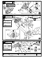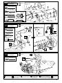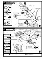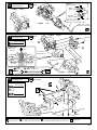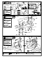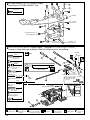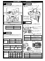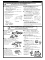
1
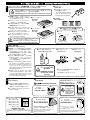
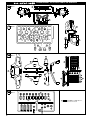
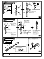
※ご使用前にこの説明書を良くお読みになり十分に理解してください。
Before commencing assembly, please read these instructions thoroughly!
R
THE FINEST RADIO CONTROL MODELS
Size
GP 4WD
組立/取扱説明書
INSTRUCTION MANUAL
Radio Controlled .15 Engine Powered Touring Car Series
SuperTen GP FW-04 4WD
D2 AMG Mercedes CLK
D2 AMG メルセデス CLK
目 次 INDEX
●キットの他にそろえる物 REQUIRED FOR OPERATION
●プロポの準備
RADIO PREPARATION
●組立て前の注意 BEFORE YOU BEGIN
●ランナー付プラパーツ配置図 ARRANGEMENT OF PLASTIC PARTS ON RUNNERS
●本体の組立て ASSEMBLY
●セッティングガイド ADJUSTMENT
●取扱いの注意 OPERATING YOUR MODEL SAFELY
●スペアパーツ・オプションパーツリスト SPARE PARTS & OPTIONAL PARTS
●分解図 EXPLODED VIEW
安全のための注意事項
この無線操縦模型は玩具ではありません!
●この商品は高い性能を発揮するように設計されています。
組立てに不慣れな方は、模型を良く知っている人にアド
バイスを受け確実に組立ててください。
●小さい部品があるので、組立て作業は、幼児の手がとど
かない所で必ず行ってください。
●動かして楽しむ場所は万一の事故を考えて、安全を確認
してから責任をもってお楽しみください。
●組立てた後も、説明書がいつでも見られるように大切に
保管してください。
SAFETY PRECAUTIONS
This radio control model is not a toy.
●First-time builders should seek the advice of experienced modellers
before commencing assembly and if they do not fully understand
any part of the construction.
●Assemble this kit only in places out of children's reach!
●Take care before operating this model.
You are responsible for this model's assembly and safe operation!
●Always keep this instruction manual ready at hand for quick
reference, even after completing the assembly.
※製品改良のため、予告なく仕様を変更する場合があります。 SPECIFICATIONS ARE SUBJECT TO CHANGE WITHOUT NOTICE.
© 2000 KYOSHO/禁無断転載複製
2∼3
3
4∼5
5∼6
7 ∼ 26
27
28
29 ∼ 31
32 ∼ 33
No. 31001
キットの他にそろえる物(1) REQUIRED FOR OPERATION (1)
1
2チャンネル2サーボ無線操縦機(プロポ)と電池ボックス
Minimum 2 channel radio with 2 servos, and battery box.
注意
●Because there are stick-type and
wheel-type transmitters, use which
ever fits your convenience best.
●Switch the reverse (transmitter) for
the steer-ing and throttle control.
●For more information on the radio,
refer to its instruction manual.
2
■スティックタイプ
Stick-type
2ch radio.
AA
AA
使用できるサーボ・受信機サイズ
■ハンドルタイプ
Wheel-type
2ch radio.
Suitable servos & receiver
■サーボ
Servo
■受信機
Receiver
31∼36mm
このサイズのサーボでも一部取付出来ないものもあります。
アッパーデッキを加工して取付けてください。
CAUTION: If servos are not able to install, eaven
this size. Need to modify upper deck.
31∼41mm
16∼20mm
∼32mm
∼48mm
燃料と始動用具
Required for engine starting:
●模型用エンジンは専用のグロー燃料が必
要です。ガソリンや灯油は使用できませ
んので注意してください。また、グロー
燃料は揮発性が高く引火しやすいので取
扱いには充分注意してください。
●エンジン始動にはその他に、プラグを赤
熱させるプラグヒーター(ブースターコ
ード+乾電池)、プラグを脱着するプラ
グレンチが必要です。
塗料と筆
■グロー燃料、燃料ポンプ
Glow Fuel & Fuel Pump
ガソリンや灯油は
使用禁止
警告
WARNING: Gasoline
or kerosene cannot
be used.
■筆
PAINT BRUSH
Paint and Brush
●For painting the body, use Kyosho
paints for models!
No.1841
1842
1843
1859
1860
(1mm x 5m)
(1.5mm x 5m)
(2.5mm x 5m)
(0.4mm x 8m)
(0.7mm x 8m)
Micro
e
e Tap
n Lin
KYOSHO
ミクロンラインテープ
MICRON LINE TAPE
マスキング、細部デザイン用伸縮自在テープです。
Super-flexible tape for masking and detail designing
jobs.
■ブースターコード
Booster Cord
■プラグレンチ
Plug Wrench
HANDY
FUEL
●エンジン始動に必要な用具(上記3点)を
セットにしました。
No.73301 スターターパック
No.76301∼76711
京商スプレーカラー
KYOSHO SPRAY COLOR
●ボディの塗装には塗料が必要です。
京商ではモデル用塗料、スプレーを
用意していますのでご利用ください。
2
■単3乾電池
AA-size Batteries
AA
●Engines for R/C models require glow fuel.
Be careful not to purchase gasoline or
kerosene by mistake; both cannot be
used! Also, be very careful when han-dling glow fuel which is hi-ghly inflamma-ble and high-explosive!
●Besides glow fuel, engines also require
engine starting equipment. This comprises a glow plug heater (booster cord &
batteries) and a plug wrench for removing and installing the glow plug.
3
●プロポセットに付いていると
きは必要ありません。
If already included with the
radio, no battery box needs
to be pur-chased separately.
地上用(自動車用)のプロポ(2チャンネル2サーボ仕様)セットを
必ず使用してください。(地上用以外使用禁止)
CAUTION: Only use a surface radio with 2 channels and 2 servos!
●送信機にはスティックタイプとハン
ドルタイプがありますが、お好みの
タイプを用意してください。
●ステアリングサーボ、スロットルサ
ーボ共にリバースで使用します。
●プロポの取扱いは、プロポに付属の
説明書を参考にしてください。
注意
■電池ボックス
Battery Box
No.2230
ポリカカラー
POLYCA COLOR
No.96701∼96703
D-フレックスカラーデカール
D FLEX COLOR DECAL
伸縮自在の特殊素材で3次曲面
にもきれいに貼れる粘着シートです。
Self-adhesive super-flexible sheets that
bond to polycarbonate - even when
applied to curved surfaces.
注意
スプレーカラーを
使用する場合、缶
の説明を良く読ん
でください。
CAUTION: Before
using spray colors,
always read their
explanations!
FUELPROFF PAINT
K Y O SH O
S PR
AY CO LO R
R
No.1947
マスキングカバーシート
MASKING SHEET
マスキングテープとビニール
シートが一体になった広範囲
マスク用テープです。
For safe masking jobs, use this plastic masking
sheet featuring one self-adhesive edge.
キットの他にそろえる物(2) REQUIRED FOR OPERATION (2)
4
組立てに必要な工具
■+ドライバー(大、中、小)
Tools required
Phillips Screw Driver (L.M.S)
キットに入っている工具
注意
TOOLS INCLUDED
■六角レンチ(1.5mm, 2mm, 2.5mm, 5mm)
■カッターナイフ
■ラジオペンチ
Hex Wrench (1.5mm, 2mm, 2.5mm, 5mm)
使用する工具の取扱いには、充分
注意してください。
CAUTION: Handle tools carefully!
Sharp Hobby Knife
Needle Nose Pliers
■キリ
Awl
■ニッパー
Wire Cutters
■瞬間接着剤
Instant Glue
■十字レンチ
Cross Wrench
■ゴム系接着剤
Rubber Cement
■グリス
Grease
ゴム系接着剤
GREASE
No.94402
ロックタイト 中強度
LOCTITE
Midium Strength
ラウンドカッター&サンダー
ROUND CUTTER & SANDER
スペシャルテーパーリーマー
SPECIAL TAPER REAMER
No.1829
ボディのカット、仕上げ用。曲線部分も楽に
作業ができます。
For trimming bodies. Cutting along curved
lines never was so easy!
ビスの緩みを防ぎます。
To prevent the screws
from becoming loose.
プロポの準備
No.80311
下穴加工が不要で、直接1mm∼15mmの正確な
穴あけができる工具です。
No need to pre-drill!
Drills neat 1mm to 15mm holes directly!
RADIO PREPARATION
3
●プロポを下の順序にしたがってセットします。
Set up the radio control system as indicated below.
12
2
8 ON
10 OFF
9
4
▲スイッチ
Switch
7 ON
5
11 OFF
1
6
▲送信機
Transmitter
●始める時
▲サーボ
Servo
▲受信機
Receiver
●START
1 単3乾電池をセットする。(送信機)
2 アンテナをのばす。(送信機)
1 Insert AA-size dry batteries. (Transmitter)
2 Extend the antenna. (Transmitter)
3 単3乾電池をセットする。(電池ボックス)
3 Insert AA-size dry batteries. (Battery Box)
4 単3乾電池をセットした電池ボックスの
4 Connect the battery box.
コネクターをつなぐ。
5 アンテナをのばす。(受信機)
6 トリムを中央にセットする。
7 スイッチを入れる。(送信機)
8 スイッチを入れる。(受信機)
9 スティックを動かしてサーボが動いているか確認。
●終わる時
5 Extend the antenna. (Receiver)
6 Center the trims.
7 Switch on the transmitter.
8 Switch on the receiver.
9 Make sure the servos move according to
your transmitter inputs.
●FINISH
10 スイッチを切る。(受信機)
10 Switch off the receiver.
11 スイッチを切る。(送信機)
11 Switch off the transmitter.
12 アンテナを縮める。(送信機)
12 Retract the antenna. (Transmitter)
3
組立て前の注意(1) BEFORE YOU BEGIN (1)
1
組立てる前に説明書を良く読んで、おおよその構造を理解してから組立てに入ってください。
2
キットの内容をお確かめください。万一不良、不足がありましたら、お買い求めの販売店にご相談いただくか、当社「ユーザー相談室」までご連絡ください。
3
説明書の見かた
Read through the manual before you begin, so you will have an overall idea of what to do.
Check all parts. If you find any defective or missing parts, contact your local dealer or our Kyosho Distributor.
How to read the instruction manual:
〔説明例 Example〕
1
フロントサスペンション
Front Suspension
4 5 x 10mm メタル
Metal Bushing
説明書内では多くのマークが使用
されています。マークに注意して
組立てを進めてください。
This instruction manual uses several symbols. Please note them
during the entire assembly.
No.4, No.5, No.6
1
4
5
3
5 キングピン
King Pin
4
6
4
6 5.8mm ピロボール(黒)
Pillow Ball (Black)
7
2
R
2
L
5
小物部品の名前、原寸図、使用数。
Key Number, Part Name, True-to-scale
Diagram, Quantity Used
4
説明書に使われているマーク
Symbols used throughout the instruction manual, comprise:
2mmの穴をあける(例)。
Drill holes with the specified
diameter (here: 2mm).
原寸図
True-to-scale diagram.
瞬間接着剤で接着する。
Apply instant glue (CA glue, super glue).
をカットする。
Cut off shaded portion.
別購入品
Must be purchased separately!
グリスを塗る。
Apply grease.
余分をカットする。
Cut off excess.
注意して組立てる所。
Pay close attention here!
ゴム系接着剤で接着する。
Apply rubber cement.
仮止め。
Tentatively tighten.
2セット組立てる(例)。
Assemble as many times as
specified (here: twice).
可動するように組立てる。
Ensure smooth non-binding
movement while assembling.
オプションのベアリングの品番。
例 : No.1901
Ball bearings are optional!
(with optional part no.)
左右同じように組立てる。
Assemble left and right sides
the same way.
番号の順に組立てる。
Assemble in the specified
order.
使用する袋詰。
Part bags used.
x2
4
8
キット内の部品は、ビス類を除いてキー
No.が付けられています。スペアパーツを
購入する時はキーNo.を参照して下さい。
All parts except screws are identified by
key numbers. For purchasing spare parts,
find the key no. of the part needed in the
spare part list and refer to the left column
to look up the corresponding order no.
2mm
1901
組立て前の注意(2) BEFORE YOU BEGIN (2)
5
キットには、形や長さが違うビスや小物部品が多く入っています。説明書には原寸図がありますので確認してから組立ててください。
また、ビス類は多めに入っているものもありますので、予備としてお使いください。
This kit contains screws and hardware in different metric sizes and shapes.
Before using them, check the screws on the true-to-scale diagrams on the left side in each assembly step. Some screws are extras.
●ビスの種類 SCREWS
ビス Screw
●小物部品のサイズ例 OTHER HARDWARE
TPビス
Self-tapping (TP) Screw
3x12mm ビス
Screw
3mm ワッシャー・ナット
Washer・Nut
3mm
TPサラビス
TP F/H Screw
キャップビス
Cap Screw
3mm
3mm
12mm
3x12mm サラビス
F/H Screw
サラビス
Flat Head (F/H) Screw
E3 Eリング
E-ring
セットビス
Set Screw
5x10mm メタル・ベアリング
Metal Bushing・Bearing
5mm
3mm
12mm
6.8mm
10mm
TPビスは、部品にネジを切りながらしめつけるビスです。しめこみが固い場合がありますが、
Correct
部品が確実に固定されるまでしめこんでください。ただし、しめすぎるとネジがきかなくなり
ますので、部品が変形するまでしめないでください。
Wrong
Self-tapping (TP) screws cut threads into the parts when being tightened. Excessive force may
permanently damage parts when tightening TP screws. It is recommended to stop tightening when
the part is attached or when some resistance is felt after the threaded portion enters the plastic.
102
No.1
しめすぎ
Overtightened.
ビスがきかない
The threads are stripped.
ARRANGEMENT OF PLASTIC PARTS ON RUNNERS
101
100
F
ランナー付プラパーツ配置図
H
S
6
6.8mm ピロボール
Pillow Ball
110
107
13
13
144
111
13
13
108
14
106
1
2
109
3
39
No.3
84
37
38
40
143
142
98
No.4
51
52
部分の部品は、使用しません。
Shaded Parts are not used.
53
5
ランナー付プラパーツ配置図
ARRANGEMENT OF PLASTIC PARTS ON RUNNERS
85
No.5
71
70
74
No.6
63
G-10
G-6
G-1
G-6
G-1
G-4
G-4
G-5
62
G-5
64
G-3
G-3
No.7
140
89
136
132
87
113
137
86
88
No.9
135
121
105
104
141
部分の部品は、使用しません。
Shaded Parts are not used.
145
120
6
133
139
1
ステアリング
Steering
No.1
6
24mm
3mm ナット
Nut
1
2
5
1
1
9 5.8mm ピロボール(銀)
Pillow Ball (silver)
3
3mm
1
5 サーボセイバースプリング
Servo Saver Spring
6 セイバーナット
Saver Nut
2
9
1
1
2
ステアリング
Steering
No.1
3mm ナット
Nut
2.6mm
11 ステアリングピン
Steering Pin
9
4
2
10 3 x 6mm メタル
Metal Bushing
4
2.6mm
3mm
9
3mm
2
3mm
9 5.8mm ピロボール(銀)
Pillow Ball (silver)
8
3mm
2
2.6mm
10
ナイロンナット
Nylon Nut
2
3
11
ステアリング
Steering
No.1
14
1902
13
3 x 8mm サラビス
F/H Screw
2
13
12 ユニクランクシャフト
Unicrank Shaft
13
15
2
13 5 x 8 x 2.5mm プラメタル
Plastic Bushing
1902
144
13
4
12
12
3x8mm
3x8mm
使用する袋詰。
Part bags used.
をカットする。
Cut off shaded portion.
可動するように組立てる。
Ensure smooth non-binding
movement while assembling.
グリスを塗る。
Apply grease.
1901
オプションのベアリングの品番。
Ball bearings are optional !
(with optional part no.)
7
4
デフギヤ
Gear Differential
No.2
20
21
16
21
2 x 8mm TPビス
TP Screw
2x8mm
17
8
19 3 x 20mm シャフト
Shaft
2
21 Oリング
O-ring
17
16
18
4
5
20
ギヤボックス
Gearbox
18
19
x2
2x8mm
No.2
24
4x4mm
平らな面にセットビスを固定する。
Firmly tighten the set screws onto the flat spots.
22
5mm
4x4mm
25
22
5mm
23
3x10mm
23
デフギヤ
Gear Differential
28
リヤ
Rear
26
3x10mm
4x4mm
27
3x10mm
フロント
Front
4 x 4mm セットビス
Set Screw
27 5 x 10mm ベアリング
Ball Bearing
23
5
3 x 10mm TPビス(銀)
TP Screw (Silver)
12
4
28 E4
22 8 x 14mm ベアリング
Ball Bearing
Eリング
E-ring
1
5mm
ワッシャー
Washer
4
使用する袋詰。
Part bags used.
8
グリスを塗る。
Apply grease.
4
x2
2セット組立てる(例)。
Assemble as many times as specified.
平らな面にセットビスを固定する。
Firmly tighten the set screws onto
the flat spots.
x1
x1
ネジロック剤を塗る。
Apply threadlocker (screw cement).
フロント用
For Front
リヤ用
For Rear
6
フロントサスペンション
Front Suspension
4 x 4mm セットビス
Set Screw
No.3
< 左側用
Left >
1mm
2
9 5.8mm ピロボール(銀)
Pillow Ball (silver)
31
2
32
32 12 x 18mm ベアリング
Ball Bearing
2
Lのマーク
“L” marked
< 右側用
34
Right >
29
30
33 6 x 12mm ベアリング
Ball Bearing
35
R
34
2
Rのマーク
“R” marked
34 11mm ピロボール
Pillow Ball
35
4x4mm
33
36
4x4mm
4
35 11mm ピロボールナット
Pillow Ball Nut
平らな面にセット
ビスを固定する。
Firmly tighten the
set screws onto
the flat spots.
4
7
フロントサスペンション
Front Suspension
内側
Inside
36
39
No.3
< 右側用
3 x 3mm セットビス
Set Screw
< 左側用
Right >
Left >
39
2
37
3 x 10mm セットビス
Set Screw
2
9 5.8mm ピロボール(銀)
Pillow Ball (silver)
六角レンチ(2.5mm)
Hex Wrench (2.5mm)
40
3x3mm
2
146 E3
六角レンチ(5mm)
Hex Wrench (5mm)
9
Eリング
E-ring
2
38
3x10mm
41
車高調整用。
For adjusting the
ride height.
41 サスシャフト(E)
Suspension Shaft (E)
2.5mm
42
2
42 サスシャフト(D)
Suspension Shaft (D)
40
2
9
146
1mm
使用する袋詰。
Part bags used.
可動するように組立てる。
Ensure smooth non-binding
movement while assembling.
左右同じように組立てる。
Assemble left and right sides the same way.
9
8
フロントサスペンション
Front Suspension
3 x 10mm TPビス(銀)
TP Screw (Silver)
2
30
142
No.3
< 左側用
約5mm
approx. 5mm
142
Left >
約5.5mm
approx. 5.5mm
143
3x10mm
< 右側用
9
六角レンチ(2.5mm)
Hex Wrench (2.5mm)
29
交互に少しずつねじ込む。
Tighten this 2 screws reciprocally.
Right >
フロントギヤボックス
Front Gearbox
フロントサスペンション
Front Suspension
内側
Inside
43
向きに注意。
Note the direction.
44
No.3
43
44
3 x 12mm TPサラビス
TP F/H Screw
43
4
44 Oリング
O-ring
2
向きに注意。
Note the direction.
前
Front
3x12mm
3x12mm
10
ステアリング
Steering
No.3
46
x2
45
45
45 5.8mm ボールエンド(L)
Ball End (L)
4
46 3 x 20mm セットビス
Set Screw
2
約8mm
approx. 8mm
使用する袋詰。
Part bags used.
10
左右同じように組立てる。
Assemble left and right sides
the same way.
原寸図。
True-to-scale diagram.
x2
2セット組立てる(例)。
Assemble as many times as specified.
グリスを塗る。
Apply grease.
11
センターギヤボックス
Center Gearbox
No.4
49
3 x 6mm TPビス(銀)
TP Screw (Silver)
1
3 x 10mm TPビス(銀)
TP Screw (Silver)
2
3 x 30mm ビス
Screw
50
1
12
22 8 x 14mm ベアリング
Ball Bearing
3 x 3mm セットビス
Set Screw
3 x 12mm ビス
Screw
53
3x30mm
2
22
19 3 x 20mm シャフト
Shaft
22
3x6mm
1
センターギヤボックス
Center Gearbox
4 x 4mm セットビス
Set Screw
48
19
1
50 18mm アルミスペーサー
Aluminium Spacer
47
フロント側
Front
3x10mm
向きに注意。
Note the direction.
51
52
No.4
6mm
59 60 は向きに注意。
Note the direction for
59 and 60 .
2
55
1
上
Top
3x3mm
55
2
約5.5mm
approx. 5.5mm
4x4mm
54
57 ブレーキピストン
Brake Piston
1
4x4mm
60
59
58
59
60
57
3x12mm
23
56
平らな面にセットビスを固定する。
Firmly tighten the set screws onto the flat spots.
13
センターギヤボックス
Center Gearbox
3x12mm
No.4
3 x 12mm TPサラビス
TP F/H Screw
2
4
61
3
1
3x12mm
3x12mm
使用する袋詰。
Part bags used.
ネジロック剤を塗る。
Apply threadlocker
(screw cement).
ゴム系接着剤で接着する。
Apply rubber type glue.
番号の順に組立てる。
Assemble in the
specified order.
可動するように組立てる。
Ensure smooth non-binding
movement while assembling.
グリスを塗る。
Apply grease.
11
14
リヤサスペンション
Rear Suspension
No.5
32 12 x 18mm ベアリング
Ball Bearing
< 左側用
31
Left >
32
2
Lのマーク
“L” marked
68 9mm ピロボールナット
Pillow Ball Nut
6
65
< 右側用
68
Right >
66
67 9mm ピロボール
Pillow Ball
67
67
Rのマーク
“R” marked
4x4mm
6
68
4 x 4mm セットビス
Set Screw
68
33
2
33 6 x 12mm ベアリング
Ball Bearing
36
4x4mm
2
15
六角レンチ(5mm)
Hex Wrench (5mm)
67
平らな面にセット
ビスを固定する。
Firmly tighten the
set screws onto
the flat spots.
リヤサスペンション
Rear Suspension
No.5
< 左側用
Left >
内側
Inside
36
62
六角レンチ(2.5mm)
Hex Wrench (2.5mm)
72
車高調整用。
For adjusting the
ride height.
70
72 サスシャフト(F)
Suspension Shaft (F)
3x14mm
2mm
2
3x10mm
73 サスシャフト(C)
Suspension Shaft (C)
69
73
64
2
3 x 14mm キャップビス
Cap Screw
2
< 右側用
9 5.8mm ピロボール(銀)
Pillow Ball (silver)
64
63
Right >
9
62
2
69 6.8mm ボール
Ball
2
3 x 10mm セットビス
Set Screw
2
使用する袋詰。
Part bags used.
12
中央の穴を使用。
Use center hole.
63
71
可動するように組立てる。
Ensure smooth non-binding movement while assembling.
左右同じように組立てる。
Assemble left and right sides the same way.
16
リヤサスペンション
Rear Suspension
< 右側用
約4.5mm
approx. 4.5mm
No.5
約4mm
approx. 4mm
Right >
約4.5mm
approx. 4.5mm
< 左側用
17
リヤサスペンション
Rear Suspension
3 x 10mm TPビス(銀)
TP Screw (Silver)
2
向きに注意。
Note the
direction.
交互に少しずつねじ込む。
Tighten this 3 screws reciprocally.
Left >
六角レンチ(2.5mm)
Hex Wrench (2.5mm)
< 右側用
No.5
Right >
3x10mm
43
74
前
Front
リヤギヤボックス
Rear Gearbox
43
内側
Inside
43
向きに注意。
Note the direction.
< 左側用
18
リヤサスペンション
Rear Suspension
No.3, No.5
3 x 12mm TPサラビス
TP F/H Screw
76
4
44 Oリング
O-ring
2
1
1
Left >
44
4
75
3
3x12mm
3x12mm
使用する袋詰。
Part bags used.
番号の順に組立てる。
Assemble in the specified order.
左右同じように組立てる。
Assemble left and right sides the same way.
3x12mm
グリスを塗る。
Apply grease.
13
19
ダンパー
Shock
No.6
45 5.8mm ボールエンド(L)
Ball End (L)
77
4
78 ダンパーシャフト
Shock Shaft
x4
45
約13mm
approx. 13mm
G1
4
77 E2.5 Eリング
E-ring
8
シャフトに布をまき、つかむ。
Cover the shaft with cloth before
gripping it with pliers.
79
78
77
x4
20
ダンパー
Shock
No.6
もう一度図の位置
までオイルを足す。
Add oil one more
time up to the brim.
80
ピストンを下げ、
オイルを図の位置
まで入れる。
Pull down the piston
and slowly fill in oil.
オイル
Oil
0~1mm
G3
81
0~1mm
79
ピストン
Piston
81 を 79 にかぶせ、あふれた
オイルをふきとり、80 G3を
組立てる。
Put 81 onto 79 , wipe up any
excess oil and screw on G3
together with 80 .
ゆっくり上下させ、
気泡をとる。
Then, gently move
the piston up and
down to get rid of
air bubbles.
21
ダンパー
Shock
x4
スプリングを縮めてG6を入れる。
Compress the spring and install G6.
No.6
83 5.8mm ボール
Ball
スムーズに動くか確認する。
スムーズに動かないときは、
オイルを入れ直す。
Ensure smooth piston
move-ment.
Should a piston not
move smoothly.
4
G6
G5
G4
厚さ1mmのスペーサーを使用します。
Use 1mm size spacer.
82
83
1mm
x4
使用する袋詰。
Part bags used.
14
x4
4セット組立てる(例)。
Assemble as many times as specified.
22
フロントダンパー
Front Shock
No.3
3 x 14mm キャップビス
Cap Screw
2
84
3x14mm
23
リヤダンパー
Rear Shock
No.5, No.7
3x10mm
3 x 14mm キャップビス
Cap Screw
3x10mm
2
2
86
2
1
3 x 10mm TPビス(銀)
TP Screw (Silver)
4
1
3x10mm
3x10mm
85
3
3x14mm
3
24
フロントバンパー
Front Bumper
No.7
3 x 10mm TPビス(銀)
TP Screw (Silver)
2
3 x 12mm TPサラビス
TP F/H Screw
87
1
3x12mm
3x10mm
使用する袋詰。
Part bags used.
左右同じように組立てる。
Assemble left and right sides the same way.
番号の順に組立てる。
Assemble in the specified order.
15
25
サイドバンパー
Side Bumpers
FUTABA SRN-31F コントロールブロックを使用する
時のみ取付ける。
In case of using Futaba SRN-31F control block unit
assemble left side bumper.
No.7
3 x 8mm サラビス
F/H Screw
88
2
(4)
3x8mm
3x8mm
3x8mm
89
3x8mm
26
燃料タンク
Fuel Tank
No.8
91 シリコンチューブ
220mmにカットする。
Cut to one 220mm piece.
Silicone Tube
91 シリコンチューブ
Silicone Tube
80mmにカットする。
Cut to one 80mm piece.
90
90
バリを取る。
Triming
3 x 12mm TPサラビス
TP F/H Screw
2
3x12mm
0
10
20
使用する袋詰。
Part bags used.
16
30
40
50
60
70
80
90
100
110
120
130
140
150
160
170
180
27
エンジン
Engine
No.8
3 x 8mm ビス
Screw
紙1枚分のすき間をつくって
固定する。
Tighten the screws with
one sheet of paper inserted
between both gears.
4
3 x 8mm サラビス
F/H Screw
3
エンジンアッセンブリー
Engine Assembly
91 シリコンチューブ(80mm)
Silicone Tube (80mm)
92
3x8mm(F/H)
3x8mm(F/H)
3x8mm
3x8mm
28
3mm
エンジン
Engine
No.4, No.8
3 x 12mm TPサラビス
TP F/H Screw
2
94
96
147
97
93
96
3 x 30mm キャップビス
Cap Screw
2
3mm 座付ナット
Nut
4 x 4mm セットビス
Set Screw
4x4mm
95
2
99
1
98
前から見た図
Front View
97
90
3x30mm
90 燃料タンクと 97 マフラーが
接触しないように取り付ける。
Assemble muffler hke picture.
使用する袋詰。
Part bags used.
原寸図。
True-to-scale diagram.
3x12mm
余分をカットする。
Cut off excess.
17
29
プロポ
Radio
ステアリングサーボ
Steering Servo
No.1, No.9
2.6 x 8mm ビス
Screw
30
SANWA
KO
JR
HITEC
F
FUTABA
101
S
1
F
102
9
H
3mm ナット
Nut
2.6mm ナット
Nut
90¡
3 x 10mm TPビス(銀) 3 x 8mm ビス
TP Screw (Silver)
Screw
9 5.8mm ピロボール(銀)
Pillow Ball (Silver)
1
7
7 5.8mm ピロボール(黒)
Pillow Ball (Black)
1
サーボに付属するビスと同じタイプを選ぶ。
Use the same type of screw as supplied with the servos.
2.6 x 8mm TPビス
TP Screw
プロポ付属のサーボホーンを使用する場合。
In case of using servo horn which come with transmitter.
100
3mm
2.6mm
2
15~16mm
3x15mm
プロポ
Radio
No.1, No.9
3x15mm
106
スロットルサーボ
Throttle Control Servo
3 x 10mm TPビス(銀)
TP Screw (Silver)
2
3x18mm
107
3 x 15mm TPビス
TP Screw
3x18mm
4
103
3 x 18mm TPビス
TP Screw
4
3x10mm
3x10mm
104
105
105
104
ステアリングサーボ
Steering Servo
105
105
31
3x10mm
メカボックス
Radio Box
No.1
2 x 8mm TPビス
TP Screw
2.6x25mm
2x8mm
3 x 10mm TPビス(銀)
TP Screw (Silver)
3
2.6 x 25mm ビス
Screw
111
スイッチ
Switch
3x10mm
3x10mm
108
1
1
109
スイッチ
Switch
使用する袋詰。
Part bags used.
18
をカットする。
Cut off shaded portion.
110
別購入品。
Must be purchased separately!
可動するように組立てる。
Ensure smooth non-binding
movement while assembling.
32
プロポ
Radio
アンテナ
Antenna
No.7
113
3x10mm
112
3 x 10mm TPビス(銀)
TP Screw (Silver)
2
114 フックピン
Hook Pin
1
3x10mm
114
プロポの説明書を参考に、コネクター
を接続する。
Connect as per radio instruction manual.
受信機用電池ボックス
Receiver Battery Box
● メカボックス内にスペースが空く場合は、
スポンジ等を入れてください。
If receiver and battery move in the box.
Add sponge or some others for holding.
受信機
Receiver
33
3x10mm
3x12mm
シャシー
Chassis
3x10mm
3 x 10mm TPビス(銀)
TP Screw (Silver)
5
3x10mm
3 x 12mm ビス
Screw
2
34
ステアリング
Steering
No.9
90°
45 5.8mm ボールエンド(L)
Ball End (L)
90
F
2
115 3 x 30mm アジャスタブルロッド
Adjustable Rod
この部分のねじこみ量を調整して図のようにする。
Adjust degree of tightness of both parts and make
servo rod look as shown.
1
45
45
約15mm
approx. 15mm
115
使用する袋詰。
Part bags used.
別購入品。
Must be purchased separately!
原寸図。
True-to-scale diagram.
注意して組立てる所。
Pay close attention here!
19
35
プロポ
Radio
No.9
2 x 10mm ビス
Screw
3x3mm
2x10mm
1
3 x 3mm セットビス
Set Screw
2
118 2mm
119
118
ストッパー
Stopper
2
119 スプリング
Spring
3x3mm
116
1
上下の向きに注意。
Note the top
and bottom.
120
118
サーボホーン
Servo Horn
116 スロットルロッド
Throttle Rod
2mm
使用する穴。
Holes used.
117
1
2mm ナイロンナット
Nylon Nut
1
約10mm
2mm
approx.10mm
約16mm
approx.
16mm
117 ブレーキロッド
Brake Rod
1
36
プロポ
Radio
121 テーパーワッシャー
Tapered Washer
サーボ付属。
Supplied with the servo.
向きに注意。
Note the direction.
No.9
中立
Neutral
91 シリコンチューブ
121
Silicone Tube
1
約10mm
approx.
10mm
121
145
37
スロットルリンケージ調整
Throttle Linkage Adjustment
( ハイ )
( High )
No9
約1mm
approx.1mm
( スロー )
( Idle )
スロットルスト
ップスクリュー
で調整する。
Adjust with throttle
stop screw.
約1mm
approx.1mm
( ブレーキ )
( Brake )
ちぢんでいる。
Contracted.
122
スロットルストップスクリュー
Throttle Stop Screw
123
ブレーキが効きはじめる位置。
Position where brake starts working.
124
確認後、
とりつける。
Confirm the setting
before installation.
使用する袋詰。
Part bags used.
20
仮止め。
Tentatively
tighten.
可動するように組立てる。
Ensure smooth non-binding
movement while assembling.
原寸図。
True-to-scale
diagram.
をカットする。
Cut off shaded
portion.
別購入品。
Must be purchased
separately!
余分をカットする。
2mmの穴をあける(例)。
Cut off excess. 2mm Drill holes with the
specified diameter.
38
タイヤ
Wheels
129(細:フロント用)
(thin : for front)
130(太:リヤ用)
(thick : for rear)
125(細:フロント用)
127(細:フロント用)
(thin : for front)
(thick : for rear)
ホイールを回しながら半分くらいタイヤにいれる。
Fit wheels inside tyres as shown.
39
x2
x2
126(太:リヤ用)
(thin : for front)
128(太:リヤ用)
(thick : for rear)
タイヤを強くひっぱりホイールを押しこむ。
Twist the tyre onto the wheel.
フロント用
For Front
リヤ用
For Rear
ピッタリはめてからタイヤとホイールのつなぎ目に
瞬間接着剤を流し接着する。
After fitting wheels to tyres, apply instant glue as shown.
タイヤ
Wheels
< リヤ Rear >
リヤ用
For Rear
< フロント
Front >
131
131
131 ホイルボルト
Wheel Bolt
フロント用
For Front
十字レンチ
Cross Wrench
4
40
ボディマウント
Body Mounts
No.7
132
広げて入れる。
Widen the slit with a screwdriver and fit in
the snap.
132 の向きに注意して、各2つずつ作る。
Note the direction of 132 and assemble two of
each kind.
133
134
135
使用する袋詰。
Part bags used.
ゴム系接着剤で接着する。
Apply rubber type glue.
瞬間接着剤で接着する。
Apply instant glue
(CA glue, super glue).
x2
2セット組立てる(例)。
Assemble as many
times as specified.
左右同じように組立てる。
Assemble left and right
sides the same way.
21
41
ボディマウント
Body Mounts
2 x 8mm TPビス
TP Screw
No.7
4
< リヤ
3 x 10mm TPビス(銀)
TP Screw (Silver)
2
3 x 15mm TPビス
TP Screw
< フロント
Rear >
3x10mm
3x15mm
2
136
Front >
137
2x8mm
2x8mm
42
ボディ
Body Shell
6mm
3mm
3mm
3mm
6mm
3mm
3mm
3mm
3mm
使用する袋詰。
Part bags used.
22
をカットする。
Cut off shaded portion.
左右同じように組立てる。
Assemble left and right sides the same way.
3mmの穴をあける(例)。
3mm Drill holes with the specified diameter.
43
塗装
Painting
1 塗装前に、洗剤で油やよごれを洗う。
2 ウインドウ部分に、
3 塗分けはパッケージ
4 塗装後、ボディ表面の保護ビニール
Before painting, use a neutral detergent
to remove any oil residues and dirt.
内側からマスキング
シートを貼る。
Mask the windows
from the inside.
写真も参考にして
ください。
Refer to the pictures
on the box for the
color scheme.
シートをはがしておく。
After painting, remove the
protective film from the
body shell.
京商スプレーカラーでボディ内側を塗装する。
Paint the body shell from the inside using KyoshoÕs spray colors.
No.76401
クロームシルバー
Chrome Silver
No.76304
イエロー
Yellow
No.76302
ブラック
Black
マスキング
Mask
ブラック
Black
B-7
A-2
イエロー
Yellow
A-1
マスキング
Mask
クロームシルバー
Chrome Silver
クロームシルバー
Chrome Silver
44
3x6mm
プラパーツ
Plastic Parts
両面テープ
Double-sided Tape
両面テープ
Double-sided Tape
3mm
3x8mm
3 x 8mm TPビス
TP Screw
8
A-10
B-1
B-2
A-2
3mm
B-7
3x8mm
B-1
3mm
B-2
3mm
4
3mm
3x6mm
3mm
3 x 6mm TPビス
TP Screw
4
3mm ナット
Nut
クロームシルバー
Chrome Silver
ワッシャー
Washer
11
3mm
3mm
A-1
使用する袋詰。
Part bags used.
B-6
3mm
3mm
3mm
3mm
3x8mm
3x8mm
ナットは、しめすぎないように注意!
Do not overtighten the nuts !
注意して組立てる所。
Pay close attention here!
23
45
4
カッコの中は反対側用のデカールナンバーです。
The decal numbers between brackets are only for the opposite side.
デカール
Decals
6
7
57 53 56 55 54
37
36
5
1
52
2
58 11 17
9
8
12 10 59 72
30
13 15 32
9
14 79
51
2
60 16
9
8
12 61
29
62 15 31
9
78
3
55 56 53 57
79
63 ( 64 )
38
39
71
23 22 18 ( 19 )
20 ( 21 ) 73 69 ( 70 ) 80
40
34 56 55
46
9
77
9
24 ( 25 )
55 56 35
ボディ
Body Shell
67 ( 68 ) 65 ( 66 ) 26 27 ( 28 )
74 75 33 76
2
2
1
走行上の注意
Safety Precautions
走行時は、必ずボディを装着してください。
下記の場所での走行は、故障の原因になりますのでおやめください。
・シャシーにからむような草の生えているところ。
・泥地、砂地、砂利の多いところ。
定期的に、各部のビス類が緩んでないか確認してください。
番号の順に組立てる。
Assemble in the specified order.
24
Always run your car with the body shell mounted!
Do not run your car on ground:
・that is overgrown with grass.
・that is muddy, sandy or rocky.
Check all screws, nuts etc. on a regular basis for looseness.
G5(ダンパースペーサー)
ダンパースペーサー
Shock Spacer
(Shock Spacer)
3 x 10mm TPビス
TP Screw
1
3x10mm
G10(ダンパースペーサーホルダー)
(Shock Spacer Holder)
燃料フィルターの取付
Installation of Fuel Filter
燃料フィルター(M)No.39308
Fuel Filter (M)
3 x 10mm TPビス
TP Screw
2
3x10mm
140 トランスポンダーステー
Transponder Stay
39641クーリングファンセットを取付ける場合
Installation of 39641 Cooling Fan Set
3mm
3x10mm
3x30mm
52
3x6mm
51
別購入品。
Must be purchased separately!
25
FUTABA SRN-31Fユニットを取付ける場合
Installation of FUTABA SRN-31F Unit
112
141
3 x 10mm TPビス
TP Screw
1
3x10mm
スイッチカバー
Switch Boots
フタバSRN-31Fユニット
Futaba SRN-31F Unit
Lのマーク
“L” marked
Rのマーク
“R” marked
スライドキャブレター付エンジンを取付ける場合、下図を参考にしてリンケージをしてください。
In case of using slide type carburetor. Refer follouing picture for assembling.
2 x 10mm ビス
Screw
1
3 x 3mm セットビス
Set Screw
118 2mm
2x10mm
No.7
ストッパー
Stopper
3x3mm
138
139
1
119
1
139 4mm ボールエンド
Ball End
約40mm
approx. 40mm
1
120
118
117 ブレーキロッド
Brake Rod
2mm
1
138 1.6 x 145mm ロッド
Rod
117
サーボホーン
Servo Horn
上下の向きに注意。
Note the top and
bottom.
1
119 スプリング
Spring
サーボ付属。
Supplied with the servo.
1
2mm ナイロンナット
Nylon Nut
中立
Neutral
1
121 テーパーワッシャー
Tapered Washer
1
121
145
使用する袋詰。
Part bags used.
26
別購入品。
Must be purchased
separately!
可動するように組立てる。
Ensure smooth non-binding
movement while assembling.
をカットする。
2mmの穴をあける(例)。
2mm Drill holes with the
Cut off shaded
portion.
specified diameter.
仮止め。
Tentatively tighten.
原寸図。
True-to-scale
diagram.
ADJUSTMENT
セッティングガイド
1
3
ダンパー(1)
Shock (1)
G5ダンパーカラーの種類、個数を変えて、車高の調整ができます。
Adjust the ride height by changing the guantity and / or type of shock
collars used.
142 スペーサーの取付位置を変えて、キャスター角を
変更できます。
Adjust the caster by changing the location of the 142 Spacer.
142
G5 (2mm)
G5 (1.5mm)
G5 (1mm)
キャンバー角
(前後とも約1û)
Camber Angle
(for front & rear
approx. 1û)
フロントサスペンション
Front Suspension
キャスター
Caster
キャスター角 約14°
Caster : approx. 14¡
キャスター角 約8°
Caster : approx. 8¡
キャンバー角
(前後とも約1û)
Camber Angle
(for front & rear
approx. 1û)
一般的にキャスター
角を大きくすると、
コーナリング特性が
マイルドになる。
Generally, the bigger
the caster, the milder
cornering becomes.
4
車高
Ride Height
ピロボールの締込量でキャンバー角の調整ができます。
全幅 約220mm
width approx. 220mm
G5を増やす。
Increasing G5 shock collar width.
キャンバー
Camber
Adjust the camber by tightening or unscrewing the pillow ball.
車高が上がる。
Ride height becomes higher.
< フロント Front >
43 スイングシャフトが脱落するので、
ゆるめすぎないこと
Do not loosen too much since will
Swingshaft fall out.
G5を減らす。
車高が下がる。
Decreasing G5 shock collar width. Ride height becomes lower.
2
キャンバー角は、約1ûに調整してください。
Adjust camber approx. 1û
ダンパー(2)
Shock (2)
43
六角レンチ(2.5mm)
Hex Wrench (2.5mm)
ダンパースプリング、オイルをオプションパーツと変えるこ
とで、ステアリング特性を変えることができます。
Adjust the steering behaviour by changing the spring tension and / or
type of shock oil.
ダンパーのかたさ
Spring stiffness
かたい
Hard
やわらかい
Soft
フロント
シャープ
ステアリング特性
Front
Sharp
Steering
characteristics リヤ
タイヤのグリップが低くなる。
Rear Grip gets lower.
マイルド
Mild
タイヤのグリップが高くなる。
Grip gets higher.
特性
Steering Characteristics
キャンバー角 大
Camber Angle (Large)
ステアリング特性はマイルド傾向になる。
Steering becomes milder.
キャンバー角 小
Camber Angle (Small)
コーナリング初期の反応が良くなる。
Enters corners more aggressively.
リヤサスペンション
Rear Suspension
トー角
Toe Angle
< リヤ Rear >
約2°
approx. 2û
< スプリング Spring >
かたい
Hard
ダンパーのかたさ
Spring stiffness
92491 オンロードスプリング(S)
On-road
Shock Spring(S)
イエロー
Yellow
やわらかい
Soft
グリーン
Green
約2° approx. 2û
オレンジ
Orange
リヤにトー角を少しつけると、
走行安定性が向上します。
Rear toe angle give stability.
< ダンパーオイル Shock Oil >
ダンパーのかたさ
Spring stiffness
かたい
Hard
やわらかい
Soft
キャンバー角は、約1ûに調整してください。
Adjust camber approx. 1û
# 200 # 100
(96603) (96601)
# 400 # 300
(96607) (96605)
シリコンオイル
Silicone Oil
# 600 # 500
(96609) (96608)
六角レンチ(2.5mm)
Hex Wrench (2.5mm)
特性
Steering Characteristics
キャンバー角 大
Camber Angle (Large)
コーナリング初期にリヤタイヤがすべりにくくなる。
Gives rear tires more grip when entering corners.
キャンバー角 小
Camber Angle (Small)
コーナリング初期にリヤタイヤがすべりやすくなる。
Rear tire grip becomes worse when entering corners.
27
OPERATING YOUR MODEL SAFELY
次のような時、場所では走らせない。思わぬ事故の原因になります。
CAUTION: Do NOT operate the model in the following places and situations:
(Non-observance may lead to accidents!)
注意
●周囲に人がいなくて、広い安全な場所で!
1. 自動車道路では走らせない。
2. 近くに小さな子供がいたり、人の多い場所では走らせない。
3. 民家の近くや公園などでは走らせない。
4. 室内やせまいところでは走らせない。
※人にケガをさせる原因になります。また、物をこわしたり、
他人の迷惑になります。
Operate the model in spacious areas with no people
around! Do NOT operate it:
1. on roads!
2. in places where children and many people gather!
3. in residential districts and parks!
4. indoors and in limited space!
* Non-observance may account
for personal injury and
property damage!
●プロポ関係の電池残量は常にチェックする。
電池が減ってくると電波の送・受信が弱くコントロール
ができなくなり、暴走や衝突の原因なります。
Always check the dry batteries in the radio!
When the dry batteries get weaker, transmission and reception of
the radio decrease. You may lose control of your model when
operating it under such condition. This may lead to accidents!
●近くで無線操縦模型を楽しんでいる人がいる。
同じバンドでの同時走行はできません。電波が混信して
コントロールができなくなり、暴走や衝突の原因なります。
Keep in mind that people around you may also
operate a radio control model!
NEVER share the same frequency
with somebody else at the same
time! Signals will be mixed and
you will lose control of your model.
This may lead to accidents!
●車の動きがおかしい??とき。
すぐに走行を中止しておかしい原因を調べる、原因不明のまま
走行させると、思わぬ故障や事故の原因になります。
When the model is behaving strangely . . .!
Immediately stop the model and check the reason. As long as the
problem is not cleared, do NOT operate it! This may lead to further
trouble and unforeseen accidents!
事故やケガ等の危険防止のため、次のことを必ずお守りください。
CAUTION: in order to avoid accidents and personal injury,
注意
be sure to observe the following:
●燃料の取扱いは、必ず屋外で。
●燃料は、模型用グロー燃料を必ず使用する。
燃料の蒸気、排気ガスは有害です。
ガソリンや灯油の使用は、火災等の事故の原因になります。
Handle fuel ONLY
outdoors!
ONLY use glow fuel for radio control models!
Vapors and exhausts are
very noxious to health!
●回転している部分に、指や物などを入れない。
高速回転しているのでケガの原因になります。
Do NOT put fingers or any objects inside
rotating and moving parts!
Rotating / moving at high
speed, you may be
seriously injured!
Because the use of gasoline and kerosene in R/C models ac-counts for fires, do NOT use them!
●燃料は、引火性があります。
1. 火気のあるところや室内では絶対に使用しない。
2. 保管は、キャップをしっかりしめ、幼児の手の届かない冷暗
所に置くこと。
3. 使用後の空缶は、火中には投げ入れない。爆発の原因になり
ます。
Fuel is highly inflammable and
high-explosive!
1. NEVER use fuel indoors or in places
with open fires and sources of heat!
2. Store fuel ONLY in cool, dry and dark
places out of children's reach! Tightly shut the cap!
3. Do NOT dispose of empty fuel cans into a fire! There is
danger of explosion!
●燃料は、飲んだり、目に入れたりしない。
●走行直後は、エンジン、マフラー周辺は高温になって
いるので、すぐにはさわらない。
ヤケドの原因になります。
Right after use, do NOT
touch equipment on the
model such as the engine
and muffler, because they
generate high temperatures!
You may burn yourself seriously touching them!
28
万一、事故が起きた場合は、吐かせる、洗眼する等をした後、
すぐに医師の診察を受けてください。
NEITHER swallow fuel NOR let it into your eyes!
Immediate measures
should be taken:
if fuel is swallowed, in-duce vomit-ing. If fuel
gets into eyes, rinse
them and consult an
orphamologist!
スペアパーツ
品番
No.
AB-15
AB-17
BS-46
FD-21
FD-33
FD-65
FM-222
FZ-10
FZ-13
FZ-14
FZ-15
FZ-18
FZ-23
FZ-51
FZ-52
FZ-53
FZ-54
FZ-55
FZ-56
FZ-57
FZ-58
FZ-59
FZ-60
FZ-61
FZ-62
FZ-63
FZ-64
FZ-65
FZ-66
FZ-67
FZ-68
FZ-69
FZ-70
FZ-71
FZ-72
FZ-73
FZ-74
FZ-75
FZ-76
FZ-77
パーツ名
内容(キーNo.と入数)
Part Names
Quantity
クラッチシュー
153 x 2
Clutch Shoe
クラッチスプリング
154 x 4
Clutch Spring
6.8mmボール
69 x 10
6.8mm Ball
フライホイールセット
151 x 1
Flywheel Set
テールパイプ
147 x 1
Tail Pipe
GP用リンケージセット 119 139 141 x 1 105 121 x 4
Linkage Set (for GP cars) 104 120 138 145 x 2 118 x 3
クラッチベル(15T)
157 x 1
Clutch Bell (15T)
ギヤボックス
24 25 x 1
Gear Box
ファイナルデフケース
Final Differential Case 16 20 26 28 x 1 21 x 2
センタープレート
8 x1
Center Plate
11mmピロボール
34 x 2
11mm Pillow Ball
サスシャフト(C)
73 x 2
Suspension Shaft (C)
センターシャフト(リヤ)
Center Shaft (Rear) 75 76 x 1
メインシャシー(FW-04)
Main Chassis (FW-04) 15 x 1
アッパーデッキ(FW-04)
103 x 1
Upper Deck (FW-04)
ナックルアーム
29 30 x 1
Knuckle Arm
リヤハブ
65 66 x 1
Rear Hub
フロントサスアーム
Front Suspension Arm 39 40 84 143 x 2 142 x 6
リヤサスアーム
Rear Suspension Arm 62 63 64 x 2
フロントバルクヘッド
37 38 x 1
Front Bulkhead
センターバルクヘッド
50 51 52 53 98 x 1
Center Bulkhead
リヤバルクヘッド
70 71 74 85 x 1
Rear Bulkhead
バンパーセット
86 87 88 89 113 140 x 1
Bumper Set
106 107 108 109 x 1
メカボックスセット
Receiver Box Set
110 111 144
スパーギヤ(39T)
48 49 x 1
Spur Gear (39T)
ディスクホルダー
56 x 1
Disk Holder
スパーギヤシャフト
19 47 x 1
Spur Gear Shaft
フロントセンターシャフト
61 x 1
Front Center Shaft
サスシャフト(D)
42 146 x 2
Suspension Shaft (D)
サスシャフト(E)
41 x 2
Suspension Shaft (E)
サスシャフト(F)
72 x 2
Suspension Shaft (F)
スイングシャフト
43 x 2
Swingshaft
ブレーキレバー
54 55 57 x 1
Brake Lever
ホイールシャフト
31 x 2
Wheel Shaft
ホイールストッパーボルト
131 x 4
Wheel Stopper Bolt
ドライブワッシャー
36 x 4
Drive Washer
9mmピロボール
67 x 3
9mm Pillow Ball
9mmピロボールナット
68 x 3
9mm Pillow Ball Nut
11mmピロボールナット
35 x 2
11mm Pillow Ball Nut
フュールタンク(100cc)
90 x 1
Fuel Tank (100cc)
★発送
手数料
品番
No.
200
(一律)
GT-5
★定価
180
SPARE PARTS
350
LA-22
250
LA-23
650
LD-70
130
OR-111
1100
OT-5
1100
OT-28
300
OT-29
900
OT-35
200
OT-36
250
SPW-51
250
W-5161
400
1284
2000
1200
1700
KP,KY
1701
KP,KY
500
1705
500
1795
600
1901
600
1911
400
39645
350
74901
500
74901-12
500
6591
450
92601
300
92638
400
92921
250
92922
300
92971
250
92972
250
96474
250
96522
500
96592
300
450
400
パーツ名
Part Names
パイロットシャフト
Pilot Shaft
ステアリングピン
Steering Pin
セイバーシャフトセット
Servo Saver Shaft Set
クラッチベアリング
Clutch Bearing
EGボディアタッチメント
EG Body Attachment
ジョイント
Joint
デフギヤセット
Differential Gear Set
Oリング
O-ring
アッパーロッドセット
Upper Rod Set
2.6mmピロボール(黒)
2.6mm Pillow Ball (Black)
ステンレスディスクローター
Stainless Disk Rotor
レーシングダンパー(SS)
Racing Shock (SS)
5.8mmピロボール(銀)
5.8mm Pillow Ball (Silver)
蛍光ストラップ(S)
Fluorescent Strap (S)
蛍光ストラップ(M)
Fluorescent Strap (M)
カラーアンテナ(白)
Color Antenna (White)
カラーシリコンチューブ
Color Silicone Tube
5x10mmベアリング
5x10mm Ball Bearing
8x14mmベアリング
8x14mm Ball Bearing
エアークリーナー
Air Cleaner
GS15-Rエンジン
GS15-R Engine
エンジンマウントプレート
Engine Mount Plate
マフラーガスケット
Muffler Gasket
耐熱マフラージョイントパイプ
Heat-resistant Muffler Joining Pipe
スナップピン
Snap Pin
サーボセイバーチューブ
Servo Saver Tube
サーボセイバープラパーツ
Servo Saver Tube Plastic Parts
SSチューンドマフラー
Muffler
マニホールド
Manifold
6x12mmベアリング
6x12mm Ball Bearing
シリコンOリング P4.5(スリム)
Silicone O-ring P4.5 (slim)
12x18mmベアリング
12x18mm Ball Bearing
★ FOR JAPANESE MARKET ONLY.
内容(キーNo.と入数)
★発送
★定価
Quantity
手数料
152 x 1
400
10 11 x 2
250
12 x 2
300
156 158 x 1
580
136 137 x 1
133 133 134 135 x 4
600
23 x 2
300
19 x 2
17 18 x 4
750
44 x 10
115 x 4
200
45 x 8
380
7 x 10
58 x 1
200
(一律)
350
59 60 x 2
1000
45 78 79 x 2 77 x 4
80 81 82 83 Gパーツ x 2
9 x8
1200
200
124 x 10
(各)180
96 x 1
(各)250
112 x 6
500
91 x 2
400
27 x 2
700
22 x 2
700
122 123 x 1
500
150 x 1
13000
92 x 1
400
93 x 5
200
95 x 2
800
114 x 10
200
4 5 6 x1
500
1 2 3 14
100 101 102 x 1
97 x 1
93 94 x 1
13 x 4
300
1200
600
33 x 2
1200
21 x 10
300
32 x 2
1800
キットの部品の一部にはスペアパーツとして販売していない物があります。
京商ではオプションパーツを販売していますのでお買い求めください。
Some of the parts included are not available as spare parts. Purchase
optional parts instead.
400
250
300
300
1000
29
オプションパーツ
No.
FZW-12
FZW-13
FZW-14
FZW-18
FZW-22
FZW-25
FZW-26
FZW-30
FZW-51
FZW-52
FZW-53
FZW-54
FZW-55
FZW-56
FZW-60
FZW-61
FZW-62
FD-49
W0136
W0137
W5152
W5155
1295
KP,KY
1706
1707
1710
1795
KP,KY
96997
1948
39308
39401
39509
39641
39648
39651
39652
39661
39671
39696
39712
30
パーツ名
内容(キーNo.と入数)
★発送
★定価
Part Names
Quantity
手数料
チタンサスシャフト(C) 73 と交換。
1000
200
Titanium Suspension Shaft (C) instead of 73 .
(一律)
スチールデフベベルギヤ 17 , 19 と交換。
2200
Steel Differential Bevel Gear instead of 17 , 19 .
スチールデフピニオンギヤ 18 と交換。
1800
Steel Differential Pinion Gear instead of 18 .
スチールデフギヤセット
6800
Steel Differential Gear Set
カーボンステアリングプレート 8 と交換。
800
Carbon Steering Plate instead of 8 .
ハードデフケース
16 と交換。
2200
Hard Deff Case
instead of 16 .
ビスカスカップリング 75 , 76 と交換。
2400
Viscus Cup Ring
instead of 75 , 76 .
4サイクルフィッティングキット 4サイクルエンジン搭載用
4 Cycle Fitting Kit
When Mounting 4 Cycle Engines 11800
ハードメインシャシー 15 と交換。
5800
Hard Main Chassis
instead of 15 .
カーボンアッパーデッキ 103 と交換。
3800
Carbon Upper Deck
instead of 103 .
ユニバーサルスイングシャフト 23 , 43 と交換。
3000
Universal Swingshaft
instead of 23 , 43 .
フロントスタビライザーセット
1200
Front Stabilizer Set
リヤスタビライザーセット
1200
Rear Stabilizer Set
2スピードオートマチックトランスミッションセット
12000
2-Speed Automatic Transmission Set
ローハイトエンジンマウント ※リコイル付エンジンには使用できません
Low Height Engine Mount *Not available with Pull Start Engine. 2000
ハイバランスフライホイール FZW-60とセットで使用
1800
High Balance Flywheel Use with FZW-60.
ハイバランスフライホイール(2スピード) FZW-60とセットで使用
1800
High Balance Flywheel (2-speed) Use with FZW-60.
フライホイール(CZ-R) O.S., エンヤエンジン用
650
Flywheel (CZ-R)
for O.S., ENYA Engines
5.8mmハードボール(M3.0) 83 と交換。 ハードアルマイト付
500
5.8mm Hard Ball (M3.0) instead of 83 . hard anodized
6.8mmハードボール(M3.0) 69 と交換。 ハードアルマイト付
500
6.8mm Hard Ball (M3.0) instead of 69 . hard anodized
テフロンツーリングダンパー(SS)
3200
Teflon Touring Shock (SS)
アジャスタブルテフロンダンパー(SS)
3200
Adjustable Teflon Shock (SS)
5.8mmボールエンド
と交換。
蛍光ピンク/蛍光イエロー
45
5.8mm Ball End
instead of 45 . Fluorescent Pink / Fluorescent Yellow(各)300
カラーアンテナ(蛍光ピンク)
500
Color Antenna (Fluorescent Pink)
カラーアンテナ(蛍光イエロー)
500
Color Antenna (Fluorescent Yellow)
スペシャルアンテナホルダー
500
Special Antenna Holder
カラーシリコンチューブ 91 と交換。 蛍光ピンク/蛍光イエロー
Color Silicone Tube
instead of 91 . Fluorescent Pink / Fluorescent Yellow(各)400
5x8mmベアリング
4ヶ入
13 と交換。
1000
5x8mm Ball Bearing
instead of 13 . 4 pcs.
エアークリーナーオイル
1000
Air Cleaner Oil
燃料フィルター(M)
1000
Fuel Filter (M)
ウレタンフォームバンパー
300
Urethane Foam Bumper
スチールファイナルデフケース 20 , 26 と交換。
3800
Steel Final Differential Case instead of 20 , 26 .
クーリングファンセット
2800
Cooling Fan Set
スペシャルエンジンマウント O.S.製エンジン搭載用
Special Engine Mount When Mounting O.S. Engines 2500
FRPブレーキディスク 58 と交換。
1000
FRP Brake Disk
instead of 58 .
FRPブレーキディスク(薄型) 58 と交換。
2枚入
1000
FRP Brake Disk (Thin Type) instead of 58 . 2 pcs.
チューンドマフラーセット(赤) 94 , 97 と交換。
6000
Tuned Muffler Set (Red) instead of 94 , 97 .
ベスペル¨クラッチシュー 153 と交換。
2500
Vespel¨ Clutch Shoe
instead of 153 .
タイヤケース(SuperTen)
600
Tire Box (SuperTen)
SCスーパーチューンドマフラー スプリングコネクトタイプ
8000
Spring Connect Super Tuned Muffler Spring Connect Type
OPTIONAL PARTS
品番
No.
71312
71641
80312
87651
92001
92022
92411
92491
92509
92511
92613
92614
92615
92616
92617
92618
92721
92741
92915
94402
96411
★ FOR JAPANESE MARKET ONLY.
パーツ名
内容(キーNo.と入数)
★発送
★定価
Part Names
Quantity
手数料
6v-600mAhニカドバッテリー 受信機用ニカドバッテリー
200
3800
6v-600mAh Ni-Cd Battery
(一律)
6v-1000mAhニカドバッテリー 受信機用ニカドバッテリー
4000
6v-1000mAh Ni-Cd Battery
ロッキングジグ&レンチ
800
Locking Jig & Wrench
メンテナンススタンド
1800
Maintenance Stand
オンロードスプリングセット(ハードタイプ)
800
Onroad Spring Set (Hard Type)
マルチ車高ゲージ
800
Multi Ride Height Gauge
チタンアジャストロッド 30mm 115 と交換。
2本入
600
Titanium Adjust Rod 30mm instead of 115 . 2 pcs.
オンロードスプリングセット 82 と交換。
3種類入
800
Onroad Spring Set
instead of 82 . 3 types.
チタンアジャストロッド 20mm 2本入 タイロッド用
600
Titanium Adjust Rod 20mm 2 pcs. for Tie Rod
マフラーステー
強化タイプ
600
Muffler Stay
strengthened
ワンピースクラッチベル 13T 157 , 158 と交換。
1600
One-piece Clutch Bell 13T instead of 157 , 158 .
ワンピースクラッチベル 14T 1901
1600
One-piece Clutch Bell 14T 5x10mmベアリング必要
ワンピースクラッチベル 15T 5x10mm Ball Bearing
1600
One-piece Clutch Bell 15T
ワンピースクラッチベル 16T
1600
One-piece Clutch Bell 16T
ワンピースクラッチベル 17T
1600
One-piece Clutch Bell 17T
ワンピースクラッチベル 18T
1600
One-piece Clutch Bell 18T
オンロードスプリングセット(ソフトタイプ)
800
Onroad Spring Set (Soft Type)
クラッチスプリング(ハード)
500
Clutch Spring (Hard)
デュアルスプリングセット
4200
Dual Spring Assort Set
ロックタイト(中強度)
900
Loctite (medium strength)
ワンタッチプラグヒートセット
4800
One-touch Plug Heat Set
クイックフュールポンプ(250cc)
96421 Quick Fill Fuel Bottle (250cc)
HGジョイントグリス
96508 HG Joint Grease
ワンウェイベアリンググリス
96509 Oneway Bearing Grease
Teamサーキットショック5段階調整
695013 Team Circuit Shock (5 different setting)
パワーユニバーサルシャフト 31 , 43 と交換。
695014 Power Universal Shaft instead of 31 , 43 .
900
800
800
3800
3500
96601
96602
96603
96604
96605
96606
96607
96608
96609
100
150
200
シリコンオイル 250
Silicone Oil 300 各600
40cc
350
400
500
600
96610
96611
96612
96613
96614
96615
96616
96531
800
450
550
シリコンオイル 700
Silicone Oil 900 各600
40cc
1100
1200
1000
96501
96502
96503
デフギヤグリス #1000
#3000 各800
Differential
Gear Grease #5000
96504
96505
デフギヤグリス #15000
#30000 各800
Differential
Gear Grease
WHEEL, TIRE, BODY SET
ホイール, タイヤ, ボディセット
ロープロホイール(ガンメタ)
FZ-79G Low Profile Wheel (Gun metallic) 129
ロープロホイール(ホワイト)
FZ-79W Low Profile Wheel (White) 129
ロープロワイドホイール(ガンメタ)
FZ-80G Low Profile Wide Wheel (Gun metallic) 130
ロープロワイドホイール(ホワイト)
FZ-80W Low Profile Wide Wheel (White) 130
18スポークホイール(ブラック)
FZ-81BK 18-Spoke Wheel (Black)
18スポークホイール(シルバー)
FZ-81S 18-Spoke Wheel (Silver)
FZ-81W 18スポークホイール(ホワイト)
18-Spoke Wheel (White)
18スポークワイドホイール(ブラック)
FZ-82BK 18-Spoke Wide Wheel (Black)
18スポークワイドホイール(シルバー)
FZ-82S 18-Spoke Wide Wheel (Silver)
18スポークワイドホイール(ホワイト)
FZ-82W 18-Spoke Wide Wheel (White)
92683
25R
92683
25
92683
30
92683
30V
92683
40
K-ZEROスリックタイヤ25R
K-ZERO Slick Tire 25R
K-ZEROスリックタイヤ25Z
K-ZERO Slick Tire 25Z
K-ZEROスリックタイヤ30Z
K-ZERO Slick Tire 30Z
K-ZEROスリックタイヤ30V
K-ZERO Slick Tire 30V
K-ZEROスリックタイヤ40Z
K-ZERO Slick Tire 40Z
x2
600
x2
600
x2
600
x2
600
200
(一律)
600
700
600
600
700
ボディセット(AMG Mercedes CLK)
39021 Body Set (AMG Mercedes CLK)
デカール(D2)
デカール
39021-1 Decal Set (D2)
x1
decals
デカール(WARSTEINER) デカール
39022-1 Decal Set (WARSTEINER)
x1
decals
ボディセット(ポルシェGT1) リヤボディマウント穴
39622 Body Set (PORSCHE GT1) はシャシーにあわせて
ボディセット(カルソニックスカイライン) あけてください。
39834 Body Set (CALSONIC SKYLINE)
ボディセット(エッソトムスチェイサー)
39835 Body Set (ESSO TOM'S CHASER)
ボディセット(SOKマクラーレンF1-GTR)
39903 Body Set (SOK McLaren F1-GTR)
ボディセット(カストロール無限NSX)
39904 Body Set (Castrol MUGEN NSX)
ボディセット(カストロールスープラGT)
39905 Body Set (Castrol Supra GT)
3000
200
(一律)
1800
1500
4200
3800
4200
4200
4200
4200
600
フロント用
for Front
モールドメッシュ
ハイグリップタイヤ
Molded Mesh
High Grip Tires
1400
200
(一律)
1400
1400
1400
1400
92684
25R
92684
25
92684
30
92684
30V
92684
40
K-ZEROスリックタイヤ25R
K-ZERO Slick Tire 25R
K-ZEROスリックタイヤ25Z
K-ZERO Slick Tire 25Z
K-ZEROスリックタイヤ30Z
K-ZERO Slick Tire 30Z
K-ZEROスリックタイヤ30V
K-ZERO Slick Tire 30V
K-ZEROスリックタイヤ40Z
K-ZERO Slick Tire 40Z
リヤ用
for Rear
モールドメッシュ
ハイグリップタイヤ
Molded Mesh
High Grip Tires
1500
200
(一律)
1500
1500
1500
1500
ビス・ナット類 SCREW・NUT etc.
● FOR JAPANESE MARKET ONLY.
品番
No.
1101
1102
1103
1104
1105
1106
サイズ(mm)
Size (mm)
ナベビス
Round Head Screw
2x6・2x8・2x10・2x15
2.6x8・2.6x10・2.6x12・2.6x14
3x4・3x6・3x8・3x10・3 x12
3x14・3x16・3x18・3x20
4x6・4x8・4x10・4x12
3x22・3x24・3x26・3x28
バインドビス
Bind Screw
1110
1111
1112
1113
1114
1115
2.6x4・2.6x6・2.6x8・2.6x12
3x4・3x6・3x8・3x10・3x12
3x14・3x16・3x18・3x20
4x6・4x8・4x10・4x12
3x22・3x25・3x28・3x30
4x15・4x18・4x20・4x22
サラビス
Flat Head Screw
1118
1119
1120
1121
1122
1123
2.6x8・2.6x10・2.6x12・2.6x14
3x6・3x8・3x10・3x12
3x14・3x16・3x18・3x20
4x8・4x10・4x15・4x20
3x22・3x24・3x26・3x28
3x30・3x32・3x34・3x35
キャップビス
Cap Screw
1124
1125
1126
1127
1128
1129
1130
1131
2x8・2x10・2x12・2x14
2.6x8・2.6x10・2.6x12・2.6x14
3x8・3x10・3x12・3x14
3x15・3x16・3x18・3x20
3x25・3x30・3x35・3x40
4x10・4x15・4x20
4x25・4x28・4x30
4x35・4x40・4x45
入数(各)
QUANTITY
品番
No.
1132
1133
1134
1135
1136
1137
●200
5 each
5 each
5 each
5 each
5 each
5 each
1140
1141
1142
1143
2.6x14・2.6x15・2.6x16・2.6x18
2.6x6・2.6x8・2.6x10・2.6x12
3x6・3x8・3x10・3x12・3x14
3x15・3x16・3x18・3x20
4x10・4x15・4x18
5 each
5 each
5 each
5 each
5 each
5 each
品番
No.
径
mm
ナット
Nut
1171
1172
2mm・2.6mm
3mm・4mm
5 each
5 each
5 each
5 each
1147
1148
1149
1150
2.6x6・2.6x8・2.6x10・2.6x12
3x6・3x8・3x10・3x12・3x14
3x15・3x16・3x18・3x20
4x15・4x20・4x25
フランジ付キャップビス
Flanged Cap Screw
1153
1154
3x6・3x8・3x10
4x8・4x10・4x12
サラ小丸ビス
Screw
1157
2x8・2x10
セットビス
Set Screw
1160
1161
1162
1163
1164
1165
3x6・3x12・3x14・3x16
3x3・3x4・3x5・3x10
4x4・4x5・4x8・4x12
5x4・5x5・5x6
5x30・5x40
3x20・3x25
5 each
5 each
5 each
5 each
1174
1175
3mm
4mm
●200
10 each
●200
3 each
3 each
3 each
3 each
3 each
3 each
●200
10 each
10 each
10 pcs
10 pcs
ナイロンナット
Nylon Nut
1177
1178
1179
2.6mm
3mm
4mm
●200
5 pcs
5 pcs
5 pcs
フランジ付ナイロンナット
●200
Flanged Nylon Nut
1180
4mm
5 pcs
ワッシャー
Washer
1185
1186
2mm・2.6mm・3mm
4mm・5mm
Eリング
E-Clips
●200
2 each
2 each
入数(各)
QUANTITY
フランジ付ナット
●200
Flanged Nut
●200
サラタッピングビス
Flat Head Self-Tapping Screw ●200
●200
2 each
2 each
2 each
2 each
2 each
2 each
2 each
2 each
2x4・2x6・2x8・2x10
2.6x6・2.6x8・2.6x10・2.6x12
3x6・3x8・3x10・3x12・3x14
3x15・3x16・3x18・3x20
3x25・3x30・3x35
バインドタッピングビス
Bind Self-Tapping Screw
●200
5 each
5 each
5 each
5 each
5 each
5 each
入数(各)
QUANTITY
ナベタッピングビス
Round Head Self-Tapping Screw ●200
●200
5 each
5 each
5 each
5 each
5 each
5 each
サイズ(mm)
Size (mm)
1380
1381
1382
1383
1384
1385
1386
1387
1390
E1.5
E2.0
E2.5
E3.0
E4.0
E5.0
E6.0
E7.0
E10.0
●200
10 each
10 each
●150
10 pcs
10 pcs
10 pcs
10 pcs
10 pcs
10 pcs
10 pcs
6 pcs
6 pcs
ここに明記された以外のビス、ナット等は
『ユーザー相談室』にお問い合わせください。
31
< EXPLODED VIEW >
131 FZ-72
94 92972
一部パーツ販売していないパーツがあります。
Parts indentified only by key numbers are not sold individually!
93 6591
123 39645
86 FZ-60
150 74901
124 1700
122 39645
25 FZ-10
97 92971
131 FZ-72
95 92601
155 1387
FD-65
152 GT-5
118
153 AB-15
158 LD-70
120
118
119
39 FZ-55
43 FZ-69
24 FZ-10
F
E
121 FD-65
145 FD-65
22 1911
C
27 1901
20 FZ-13
133
22 1911
OT-28
135
17
60
18
16 FZ-13
19
136
23 OT-5
SPW-51
80
83
18
17
39 FZ-55
37 FZ-57
41 FZ-67
42
78
25 FZ-10
40 FZ-55
87 FZ-60
9 1284
13
13
92922
144 FZ-61
45 OT-35
6
108 FZ-61
64 FZ-56
73 FZ-18
I
5
43 FZ-69
69 BS-46
105 FD-65
104
140 FZ-60
104 FD-65
9 1284
109 FZ-61
FD-65
31 FZ-71
90 FZ-77
63 FZ-56
32 96592
105
45 OT-35
115 OT-35
33 96474
100 101 102 92922
45 OT-35
65 FZ-54
88 FZ-60
67 FZ-74
114 92638
68 FZ-75
9 1284
67 FZ-74
J
45
C
36 FZ-73
67 FZ-74
68 FZ-75
128
68 FZ-75
I
F
35 FZ-76
110 FZ-61
G
12 LA-23
34 FZ-15
36 FZ-73
72 FZ-68
107 FZ-61
G6
9 1284
45 OT-35
125
62 FZ-56
7 OT-36
46
33 96474
45
24 FZ-10
112 1705
111 FZ-61
82
A
G6
92921
G4
127
82
W-5161
103 FZ-52
4 92921
11
79
G4
70 FZ-59
91 1795
9 1284
LA-22
137
20 FZ-13
G10
3 92922
1 92922
10
29 FZ-53
B
48 FZ-62
8 FZ-14
77
32 96592
146
19 FZ-64
106 FZ-61
G5
E
G1
77
31 FZ-71
FZ-66
2
9 1284
W-5161
79
21 96522
113 FZ-60
52 FZ-58
81
23 OT-5
44 OT-29
43 FZ-69
13
G3
22 1911
W-5161
143 FZ-55
92922
H
13
14
D
21 96522
A
56 FZ-63
134
OR-111
135
26 FZ-13
28 FZ-13
44 OT-29
51 FZ-58
57 FZ-70
OT-28
23 OT-5
49 FZ-62
60
59 58 59
J
78
133
22 1911
47 FZ-64
61 FZ-65
26 FZ-13
142 FZ-55
134
76
23 OT-5
77
132
71 FZ-59
22 1911
54 FZ-70
D
21 96522
132
117 FD-65
50 FZ-58
53 FZ-58
OR-111
75
116 FD-65
38 FZ-57
44 OT-29
23 OT-5
27 1901
FZ-23
157 FM-222
G1
17
18
19
18
17
92 74901-12
1795
40
63 FZ-56
16 FZ-13
G
154 AB-17
FZ-55
84
81
77
G3
22 1911
21 96522
156 LD-70
55 FZ-70
80
83
64 FZ-56
23 OT-5
151 FD-21
98 FZ-58
62 FZ-56
66 FZ-54
43 FZ-69
94 92972
30 FZ-53
74 FZ-59
85 FZ-59
96 1701
126
H
B
35 FZ-76
129 FZ-81S
34 FZ-15
130 FZ-82S
131 FZ-72
© 2000 KYOSHO / 禁無断転載複製
32
15 FZ-51
89 FZ-60
131 FZ-72
SuperTen FW-04
33
R
THE FINEST RADIO CONTROL MODELS
京商株式会社
〒243-0034 神奈川県厚木市船子153
メーカー指定の純正部品を使用して
安全にR/Cを楽しみましょう。
●ユ−ザ−相談室直通 TEL.046-229-4115
お問い合わせは:月曜∼金曜(祝祭日を除く) 10:00∼18:00
63010011-1
PRINTED IN JAPAN