1
*AN-200A(J/GB) 05.3.1 2:29 PM ページ20
English
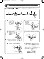
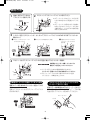
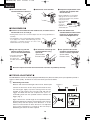
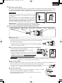
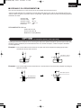
r Turn the mandrel case
counterclockwise to loosen it.
t Remove the screw mandrel.
y Prepare the replacement screw
mandrel and nosepiece with
the correct size.
* When installing the screw mandrel,
apply grease to the section which
contacts the mandrel case (shaded
area).If you do not
have any grease,
Grease
apply the
accessory
hydraulic oil or
Screw mandrel
similar lubricant.
■ REASSEMBLY ■
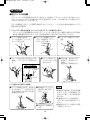
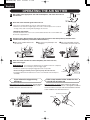
u Insert the screw mandrel into the mandrel case, and then screw it
into the tool as far as it will go.
* Working will be easier if the notch in the adaptor lock nut is facing upward before
assembly.
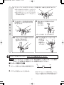
i Turn the mandrel case
counterclockwise until the notch
in the case is aligned with the
notch in the adaptor lock nut.
* The working life of the screw mandrel will be extended
if you apply some “Lobster” brand lubricating oil (sold
separately) or available machine oil to the screw
mandrel at the time of reassembly.
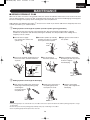
o Align the stop ring with the
notches, making sure that it
faces in the correct direction.
* The longer end should
be at the front, and
the shorter end
should be at the main
unit.
4
!0 Re-attach the front flange unit
counterclockwise using
spanner B.
(A left-handed
thread is used.)
!1 Use spanner B to turn the
nosepiece counterclockwise
until it is securely tightened.
(A left-handed
thread is used.)
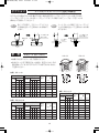
Be sure to adjust the stroke to ensure that the rivet nuts are pulled up correctly.
■ STROKE ADJUSTMENT ■
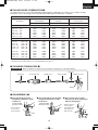
The AN-200A tool, leaves the factory equipped with M6 (metric) Nose Assembly and is pre-adjusted to provide a
stroke of 1.0mm (.040”). To find out the actual tool stroke, proceed as follows:
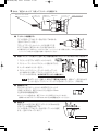
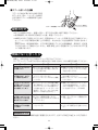
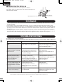
q Determining tool stroke.
Measure and record overall length of the rivet nut, before upset.
Workpiece
Thickness
Connect the tool to the air line. Grasp shank end of the rivet
nut with fingers tightly to prevent turning. Point the tool
mandrel at right angle to the rivet nut head and pull the
trigger and hold until the tool completes the cycle i.e.,
unthreading itself from the upsetted fastener. Release the
trigger. (Fig. 1)
Again, measure the overall length of the upsetted fastener.
Record the difference between measurement of the fastener
before pull-up and after pull-up. This difference “L” is the
amount of actual stroke for which the tool is now adjusted.
(Fig. 2) This information is essential to the next step of
determining the amount of stroke required.
20
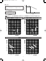
L
L=ACTUAL TOOL STROKE
Fig. 1
Fig. 2