1
2) Confirmation of U-WAVE-T
2) Installation procedure
(1) Data transmission always fails and the red LED lights up.
• Is the LCD of the Measuring tool put in the count display state?
Communication is not possible if the LCD on the connected Measuring tool is turned off or in
the data entry state. Put the Measuring tool LCD in the count display state.
• Has the battery voltage come down?
If the battery is consumed to a low voltage, the red LED is blinking and data transmission is
disabled.
Replace the battery with a new one.
• Is the U-WAVE-T installed correctly on the Measuring tool?
Recheck that the U-WAVE-T and the Measuring tool are properly mated using the supplied
connecting cable.
Also, when using the specific connecting cable (02AZD791A, B), be sure to mate the
black-marked side of the connecting cable with the U-WAVE-T.
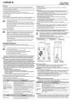
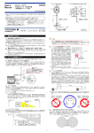
• Figure of how to attach the plate to the U-WAVE-R • Is the device ID described in the label on the U-WAVE-T set in the connecting state on the
U-WAVEPAK?
(Attachable at one of three positions.)
Unless it is in the connecting state, communication is not implemented.
Referring to read the “U-WAVE Quick manual “ and “U-WAVEPAK User’s Manual“ in
“PDF_Manual” folder of the CD supplied as a standard accessory, set up the system
correctly.
Install the U-WAVE-R at a location with a good view and eliminate any obstacle between the
U-WAVE-R and the U-WAVE-T. If installing it on a wall, etc., use the installation board
(No. 02AZD815) from among the standard accessories. To install the U-WAVE-R on a wall,
observe the following procedure.
(1) Attach the mounting plate to the U-WAVE-R backside with cross-recessed head tapping
screws (nominal size 2.6 × 6 No. A131-6221CP 2pcs.) in the standard accessories.
Screw holes are provided on the U-WAVE-R backside so that the mounting plate can be
fixed at one of three positions. Attach the mounting plate at an appropriate position
where the U-WAVE-R is easily mounted.
(2) Install the U-WAVE-R on a wall at a desired location with the two screws.
When installing the U-WAVE-R, refer to the following figure. Carefully install the U-WAVE-R
so that it will not drop from the wall.
• Figure of the installation board(Unit : mm)
Holes for mounting on a wall (2 pieces)
(2) The U-WAVE-R search cannot be executed, blinking orange color LED disappears,
and red LED blinks.
• Is the U-WAVE-T installed correctly on the Measuring tool?
Recheck that the U-WAVE-T and the Measuring tool are properly mated using the supplied
connecting cable.
If U-WAVE-T is installed correctly on the Measuring tool correctly, initialize the setting
information and then retry communication after referring “section 6 (2) in U-WAVE-T manual”
3) Confirmation of Wireless Communication Environments
Holes for attaching to the U-WAVE-R (2 pieces)
[4] Functions
1) Communication Function
The U-WAVE-R displays the data received from the U-WAVE-T.
Observe the following procedure for output operation.
(1) Connect the U-WAVE-R to a personal computer with a USB cable.
(2) Boot the U-WAVEPAK.
(3) Please read the “U-WAVE Quick manual “ and “U-WAVEPAK User’s Manual“ in
“PDF_Manual” folder of the CD supplied as a standard accessory for setting correctly.
(4) Press the DATA switch on the connecting cable connected to the U-WAVE-T or the DATA
switch on a Measuring tool to transmit data.
(5) The U-WAVE-R displays the received data and wireless transmits the confirm signal to
the U-WAVE-T.
(6) U-WAVE-T receives the confirmation signal from U-WAVE-R, and can confirm the success
(or failure) with LED (Buzzer).
Data communication is not stabilized, causing an error frequently.
• Is the U-WAVE-R separated too far from the U-WAVE-T?
• Is there any obstacle between the U-WAVE-R and the U-WAVE-T?
First, bring these instruments close to each other, and then try communication between
them. If an obstacle such as a wall or a metallic partition exists between the U-WAVE-R and
U-WAVE-T, communication may be affected adversely.
Also, the communication condition may be improved by changing the U-WAVE-R location and
orientation.
• Is any microwave oven, wireless LAN, or Bluetooth used nearby?
A wireless communication device or electric household appliance using a frequency of 2.4
GHz, which is close to the frequency used in the U-WAVE-R, might be affected adversely.
Particularly, medical equipment could cause a threat to life due to electromagnetic
interference. Carefully use the U-WAVE-R while separating sufficiently from such
equipment.
Also, check the situation of used bands at the periphery with the U-WAVEPAK and change
the current band to that with better communication quality. It may be possible to stabilize
communication.
Make an attempt on this, referring to “U-WAVEPAK User’s Manual“ in “PDF_Manual” folder of
the CD supplied as a standard accessory.
[6] Specifications
IMPORTANT
• Log in to Windows by ‘Power Users’ or above.
• The U-WAVE-PAK automatically transmits the measurement data to the active application
software (such as Microsoft Excel or Microsoft word). Before booting multiple application
software simultaneously, be sure to activate the application software that you want to use.
• U-WAVE-R receives the data from the U-WAVE-T and wireless transmits the confirmation
signal to the U-WAVE-T, even if U-WAVEPAK doesn't start .
Please confirm measurements are displayed in the application software that is before the
measurement begins that wants to be used.
Country
Code No.
Certification number
Transmission output
Distance of communication
2) Low power supply alarm
Red LED blinks when the voltage of the power supply from the personal computer decreases.
(Green LED is in the state of lighting.)
Please change to a new USB cable at such a state.
A Conformity standard
3) Initializing the setting information
If communication is disabled while using the U-WAVE-R, first refer to section 5.
If communication is still disabled, initialize the information set in section 3 to default settings,
and then retry setup.
Initialize the setting information with the following procedure.
(1) Close U-WAVEPAK activated on the personal computer, and then pull off the cable of the
U-WAVE-R from the USB cable on the computer.
(2) While holding down the INIT. switch on the U-WAVE-R, plug the cable from the U-WAVE-R
into the USB cable on the personal computer again. Wait for 3 seconds or more in this state.
The setting information is initialized. At this time check that the green LED is blinking.
(3) Implement the setup again.
IMPORTANT
Once initialization is performed, the setting information used until then is all cleared.
[5] Troubleshooting
If any trouble is not corrected even when the following actions are taken, contact a Mitutoyo
service center.
Please read the final page of “U-WAVEPAK User’s Manual“ in “PDF_Manual” folder of
the CD supplied as a standard accessory about Mitutoyo service center.
1) Confirmation of U-WAVE-R
(1) The green LED will not light up (or start blinking).
• Is the power to the personal computer turned on?
• Is the USB cable connected between the U-WAVE-R and personal computer?
The U-WAVE-R is supplied with power from the personal computer, and thereby no power
will be supplied to the U-WAVE-R unless the personal computer is turned on. Check the
USB cable for proper connection.
• Is the USB driver installed?
(2) The red LED is blinking with the green LED being lit.
• Is any undue force applied to the USB cable?
Check the connecting condition of the USB cable. Also, the USB cable might be broken
internally. Check it out by using a new USB cable.
(3) The green LED and red LED keep blinking alternately.
• Has setup been completed?
Referring to the U-WAVEPAK User’s Manual, set up the system correctly.
• Does any U-WAVE-R with the same group ID and band ID exist near the U-WAVE-R?
Set different information for each ID in the U-WAVE-R.
Japan, EU member countries, U.S.A, Canada
02AZD810D
005WWCA0167 (Japan)
VXU-02AZD810D (U.S.A)
4396B-02AZD810D (Canada)
Less than 0 dBm (1 mW)
Approx.20 m
(at line-of-sight distance under office environments)
Japan ARIB STD-T66
Europe EN 50371:2002
EN 300 440-1 V1.3.1 and EN 300 440-2 V1.1.2
EN 301 489-01 V1.6.1 and EN 301 489-03 V1.4.1
U.S.A 47 CFR Part 15.247:(Subpart :C)
47 CFR Part 15,(Subpart :B)
Canada RSS-210 (Issue 7) and RSS-Gen (Issue 2)
ICES 003 (Issue 4)
Wireless communication protocol
Communication frequency
Used band
Modulation method
Wireless communication speed
LED display
Output to a personal computer
Power supply system
Operating temperature (humidity)
Storage temperature (humidity)
External dimensions
U-WAVE-R mass
IEEE802.15.4 compatible
2.405 to 2.475 GHz
15 channels (at intervals of 5 MHz)
DSSS (Direct Sequence Spread Spectrum)
250 Kbps
Green/red
USB2.0 12 Mbps (equivalent to USB1.1)
USB bus power system
0 to 40°C (20 to 80%RH, with no condensation)
-10 to 60°C (20 to 80%RH, with no condensation)
140 × 80 × 31.6 (mm)
Approx. 130 g
○ Standard accessories
・ U-WAVE-R User’s Manual (this manual) No. 99MAL109B
・ U-WAVE QUICK Manual No. 99MAL110B
・ USB cable (1m) No. C177-008
・ An Installation board No. 02AZD815
・ Cross-recessed head tapping screws
nominal size 2.6 × 6 No. A131-6221CP 2pcs.
・U-WAVEPAK No.02ARB110 (The following contents bundle into the CD)
・ U-WAVEPAK Program
・ USB Device Driver
・ Data Collection Macro for U-WAVE
・ U-WAVEPAK User’s Manual No. 99MAL216
・ Warranty card
Mitutoyo Corporation
20-1, Sakado 1-Chome, Takatsu-ku, Kawasaki-shi, Kanagawa 213-8533, Japan