1
User Manual for BPS-4000
www.levitronix.com
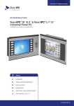
BPS-4000
6.3 bar
280 liters/min
(91 psi)
(74 gallons/min)
USER MANUAL
ATEX
This manual contains information necessary for the safe and proper use of the BPS-4000. Included are
specifications for the standard configurations of the pump system and instructions regarding its use,
installation, operation, adjustment, inspection and maintenance. For special configurations of the pump
system refer to accompanying information. Please familiarize yourself with the contents of the manual to
ensure the safe and effective use of this product. After reading this manual, please store the manual
where the personnel responsible for operating the pump system can readily refer to it at any time.
PL-4016-00, Rev02, DCO# 10-109
User Manual for BPS-4000
www.levitronix.com
Table of Content
1
SAFETY PRECAUTIONS .......................................................................................................................................... 3
2
SPECIFICATIONS ..................................................................................................................................................... 4
2.1
Specification of Components ............................................................................................................................. 4
2.2
Standard System Configurations ....................................................................................................................... 6
2.2.1
2.2.2
2.2.3
2.3
2.4
2.5
2.6
3
4.2
4.2.1
4.2.2
4.3
Overview ............................................................................................................................................................................ 21
General Installation Instructions......................................................................................................................................... 23
Electrical Installation of Controller LPC-4000.1 for Standalone Operation ........................................................................ 24
Electrical Installation of Controller LPC-4000.1 for Extended Operation ........................................................................... 24
Installation of PLC Interface for Extended Controller LPC-4000.2..................................................................................... 25
Mechanical Installation of the Pump/Motor ...................................................................................................... 27
Standard Installation Instructions and Information............................................................................................................. 27
Installation of ATEX Motors................................................................................................................................................ 27
Mechanical Installation of the Controller .......................................................................................................... 28
OPERATION ............................................................................................................................................................ 29
5.1
System Operation with LPC-4000.1 (Stand-Alone Version) ............................................................................ 29
5.1.1
5.1.2
5.1.3
5.1.4
5.2
5.2.1
5.3
5.3.1
5.3.2
6
Motor Temperature ............................................................................................................................................................ 16
Controller Temperature ...................................................................................................................................................... 20
INSTALLATION ....................................................................................................................................................... 21
4.1
Electrical Installation of Controller.................................................................................................................... 21
4.1.1
4.1.2
4.1.3
4.1.4
4.1.5
5
Pressure-Flow Curves ....................................................................................................................................... 8
NPSHr Curves ................................................................................................................................................... 9
General Environmental Conditions .................................................................................................................... 9
Basic Dimensions of Main Components .......................................................................................................... 10
ENGINEERING INFORMATION .............................................................................................................................. 13
3.1
Sealing and Material Concept.......................................................................................................................... 13
3.2
Power Consumption ........................................................................................................................................ 14
3.3
Temperature Monitoring .................................................................................................................................. 15
3.4
Thermal Management...................................................................................................................................... 16
3.4.1
3.4.2
4
Stand-Alone System Configuration ...................................................................................................................................... 6
Extended System Configuration........................................................................................................................................... 6
ATEX System Configuration ................................................................................................................................................ 7
State Diagram of LPC-4000.1 ............................................................................................................................................ 29
Standalone Operation (Button Control Mode).................................................................................................................... 30
Extended Operation (“Analog Control Mode”) ................................................................................................................... 31
Error Display on the Integrated Panel ................................................................................................................................ 31
System Operation with Controller LPC-4000.2 (PLC version) ......................................................................... 32
State Diagram of the PLC Interface ................................................................................................................................... 32
System Operation for ATEX Applications ........................................................................................................ 34
General Safety Requirements............................................................................................................................................ 34
Control of Motor Casing Temperature ............................................................................................................................... 34
INSPECTION AND MAINTENANCE ....................................................................................................................... 35
6.1
Replacement Interval of the Impeller ............................................................................................................... 35
6.2
Impeller Replacement Procedure .................................................................................................................... 35
6.2.1
6.2.2
Preparation......................................................................................................................................................................... 35
Instructions for Replacement ............................................................................................................................................. 36
7
TROUBLESHOOTING ............................................................................................................................................. 39
7.1
Troubleshooting for Operation with Controller LPC-4000.1 ............................................................................. 39
7.2
Troubleshooting for Operation with Controller LPC-4000.2 ............................................................................. 39
7.3
Troubleshooting with Service Software............................................................................................................ 39
8
TECHNICAL SUPPORT .......................................................................................................................................... 40
9
APPENDIX ............................................................................................................................................................... 41
9.1
Regulatory Status ............................................................................................................................................ 41
9.1.1
9.1.2
9.2
CE Marking ........................................................................................................................................................................ 41
ATEX Marking .................................................................................................................................................................... 41
Symbols and Signal Words.............................................................................................................................. 42
PL-4016-00, Rev02, DCO# 10-109
2
User Manual for BPS-4000
www.levitronix.com
1 Safety Precautions
CAUTION
Do not under any circumstances open the controller or motor.
Levitronix does not assume responsibility for any damage, which
occurs under such circumstances.
CAUTION
High magnetic field strength of pump impeller.
The pump system contains a rotor magnet with high field strength. This
may alter or damage the calibration of sensitive electronic devices and
measuring instruments in the immediate surroundings. Keep at a safe
distance from the rotor, computers, monitors and all magnetic data
storage media (e.g. disks, credit cards, audio, video tapes etc.)
!
WARNING
Hazardous voltage may be present.
The controller must be grounded and placed in a spill protected
environment. Do not under any circumstances open the powered
controller.
!
WARNING
High magnetic field strength of pump impeller.
The pump system contains a rotor magnet with high field strength.
Pace maker may be influenced and magnetic forces may lead to contusions. Keep distance to pace makers and handle impeller with care.
!
WARNING
TOXIC CHEMICALS may be present.
When using the system to pump chemicals skin contact and toxic
gases may be hazardous to your health. Wear safety gloves and other
appropriate safety equipment.
! WARNING
Motors for ATEX applications: only specific types of motors LPM-4000
are classified for the use in ATEX Zone 2 classified locations. Refer to
the corresponding section in the manual.
PL-4016-00, Rev02, DCO# 10-109
3
User Manual for BPS-4000
www.levitronix.com
2 Specifications
2.1 Specification of Components
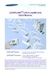
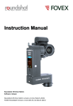
Figure 1 shows the main system components (motor, controllers, and pump head) and Figure 2 illustrates
the accessories.
2a
3b
3a
1
2a
Figure 1: Pump system BPS-4000 with standard components
8d
9a
9b
7
4b
8c
8b
9c
9d
4a
9f
9e
8a
6a
Figure 2: Pump System Accessories
PL-4016-00, Rev02, DCO# 10-109
4
User Manual for BPS-4000
www.levitronix.com
System Name
Article #
BPS-4000.1
100-90372
BPS-4000.2
100-90373
BPS-4000.16 (ATEX)
100-90436
BPS-4000.17 (ATEX)
100-90438
Pump-head
Motor
Controller
LPC-4000.1
LPM-4000.2
LPC-4000.2
LPP-4000.1
LPC-4000.1
LPM-4000.8
(ATEX)
LPC-4000.2
Note
Adaptor/Extension (0.5 - 10m) cables according to Table 4 (position 4a and 4b) have to
be ordered as separate article with specified length.
Adaptor/Extension (0.5 - 10m) cables according to Table 4 (Position 5a and 5b) have to
be ordered as separate article with specified length.
ATEX Cable Sealing System can be ordered according to Table 4 (Position 8)
Table 1: Standard system configurations
Pos.
1a
2a
2b
Component
Pump-Head
Motor
Motor
(ATEX certified)
Article Name
Article #
LPP-4000.1
100-90294
LPM-4000.2
Characteristics
Value / Feature
Impeller / Pump Housing
Reinforcing Housing
Sealing Ring
Fittings
ECTFE / PTFE (wet parts)
PP + GF30
Kalrez® perfluoroelastomer 1
ANSI Flange 1.5” Inlet / 1” Outlet
Max. Flow
Max. Diff.-Pressure
Max. Viscosity / Density
280 liters/min / 74 gallons/min
6.3 bar / 91 psi
30 cP / 1.8 g/cm3
Max. Liquid Temp.
Full performance: 70 0C / 158 0F
0
0
Limited performance: 70-90 C / 158-194 F (see Figure 6
Max. Static Pressure
0
0
8.2 bar / 119 psi @ 25 C / 77 F liquid temp. (mounted on motor)
Weight
5 kg / 11 lb
Housing
- ETFE (chemical resistant) coated Aluminum
- waterproofed (IP67 without connectors)
- protective screw (SS with PTFE coating) for mounting thread
included (see Figure 1, Pos. 2a)
Cable / Connectors
2x 3m cables with FEP jacket / 2x circular (AMP types)
Weight
35 kg / 77 lb
100-10043
LPM-4000.8
100-10048
Cable / Connectors
3a
3b
Extended
Controller
(PLC and USB)
LPC-4000.1
2x 3m cables with FEP jacket / 2x circular (M23, IP67)
100-30012
Electrical Power
1 x 200-240 V AC ±10%
3 x 200-240 V AC ±10%
4 kW
(Controller with power
supply and Enable
connector incl. in
100-90370)
Weight
6.5 kg / 14.3 lb
Voltage
Standalone
Controller
(User Panel)
II 3G Ex nA T5
II 3D Ex tD A22 IP67 T100°C
ATEX Marking
Interfaces for
Standalone Controller
Panel to set speed (automatic storage on internal EEPROM)
PLC with
1x analog input (“Speed”)
1x digital input (“Enable”)
1x digital output (“Status”)
4 - 20 mA
0 - 24 V (optocoupler)
0 - 24 V (relais)
PLC with
- up to 4 digital inputs
- up to 4 digital outputs
- up to 2 analog inputs
- up to 2 analog inputs
- up to 2 analog outputs
0 - 24V (optocoupler)
0 - 24 V (relais)
4 - 20mA
0 – 10 V
0–5V
100-30013
(Controller with power
supply and PLC
connector incl. in
100-90371)
LPC-4000.2
Interfaces for
Extended Controller
/ 1 x 22 – 18.4 A ±10%
/ 3 x 10.9 – 9.1 A ±10%
USB interface (for service and system monitoring)
Table 2: Specification of standard components
¹ Kalrez® is a registered trademark of DuPont Dow Elastomers
Pos.
Article Name
Component
Article #
Sensor Cable
Power Cable
Sensor
Power
Characteristics
Value / Feature
4a
4b
Extension Adaptor
Cable for Sensor (a)
and Power (b)
MCAS-600.1-05 (0.5m)
MCAS-600.1-30 (3m)
MCAS-600.1-50 (5m)
MCAS-600.1-70 (7m)
MCAS-600.1-100 (10m)
MCAP-4000.1-05
MCAP-4000.1-30
MCAP-4000.1-50
MCAP-4000.1-70
MCAP-4000.1-100
190-10122
190-10123
190-10124
190-10101
190-10125
190-10172
190-10173
190-10174
190-10175
190-10176
Jacket Material
Connector Types
Connector Material
PVC
Circular AMP to D-SUB
Plastics (PA)
5a
5b
Extension Adaptor
Cable for Sensor (a)
and Power (b) Wires
MCAS-600.3-05 (0.5m)
MCAS-600.3-30 (3m)
MCAS-600.3-50 (5m)
MCAS-600.3-70 (7m)
MCAS-600.3-100 (10m)
MCAP-4000.2-05
MCAP-4000.2-30
MCAP-4000.2-50
MCAP-4000.2-70
MCAP-4000.2-100
190-10158
190-10159
190-10130
190-10160
190-10161
190-10180
190-10181
190-10182
190-10183
190-10184
Jacket Material
Connector Types
Connector Material
PVC
Circular M23 (IP-67) to D-SUB
Metallic – Nickel coated
Table 3: Specification of adaptor/extension cables
Pos.
Component
Article Name
Article #
Characteristics
Value / Feature
PP / NPT 1/2”
~1 - 3 bar (14 – 43 psi)
6a
Air Cooling Module
ACM-4000.1
190-10177
Material / Connection Port
Air Pressure
6b
Air Cooling Module
ACM-4000.3
190-10190
Material
PP-EL-S with conductive additive for operation with ATEX motor
Housing Material
Cable
Supply Spec. / IP Rating
Impeller LPI-4000.1 (a)
O-Ring (b)
Pump Casing Screws (c)
Pump Motor Screws (d)
Sleeve (a) and Gasket (b)
Frame (c)
2x Cable Module (d)
PP (+ 40% Talkum)
PVC, 6m, open-end wires
20.4 – 27.6 VDC, 31.2 W, 1.3 A I IP-55
ECTFE
O-Ring, Kalrez®, 113.9 x 3.53
8pcs M10x35, PVDF
8pcs M10x35, Stainless Steel with PTFE coating
Stainless Steel and EPDM
Note:
Roxylon (EPDM rubber)
Lubricant (e) and measurement
Roxylon (EPDM rubber)
plates (f) are included.
7
Fan Cooling Module
FCM-4000.1
190-10178
8
(a - d)
Impeller Exchange Kit
IEK-4000.1
100-90522
9
(a – f)
ATEX Cable
Sealing System
ACS-A.1
(Roxtec)
100-90292
Table 4: Specification of accessories
PL-4016-00, Rev02, DCO# 10-109
5
User Manual for BPS-4000
www.levitronix.com
2.2 Standard System Configurations
2.2.1 Stand-Alone System Configuration
The stand-alone configuration of the BPS-4000 pump system (see Figure 3) consists of a controller with an
integrated user panel to set the speed manually. The speed is automatically stored in the internal EEPROM
of the controller. As an option, the speed can also be set with an analogue signal.
3a
1
4a
4b
2
Figure 3: System configuration for standalone operation (Speed setting with integrated user panel)
2.2.2 Extended System Configuration
The extended version of the BPS-4000 pump system (Figure 4) consists of a controller with an extended
PLC interface. This allows setting the speed by an external signal (see specification of Position 3b in Table
2) and enables precise closed-loop flow or pressure control in connection with either a flow or a pressure
sensor. A USB interface allows communication with a PC in connection with the Levitronix® Service
Software. Hence parameterization, firmware updates and failure analysis are possible.
3b
1
4a
4b
2
Figure 4: Extended operation (flow or pressure control) with extended controller
PL-4016-00, Rev02, DCO# 10-109
6
User Manual for BPS-4000
www.levitronix.com
2.2.3 ATEX System Configuration
Together with the standard pump-head and controllers an ATEX certified motor allows installation of motor
and pump-head within an ATEX Zone 2 area (see Figure 5). The ATEX motor (Pos. 2b in Table 2) comes
delivered with special connectors and according extension cables (Pos. 5a and 5b in Table 4). One option to
lead the cables outside of the ATEX area is an ATEX certified cable sealing system as listed in Table 4 (see
Pos. 9) and shown in Figure 2.
Cabinet Boundary for
ATEX Zone 2 Area
Fluid In
All
Controller
Types
3
1
Fluid Out
Adaptor/Extension
Cable for Sensors
Pump Head
8
Adaptor/Extension
Cable for Power
Motor Sensor Cable
5a
Motor Power Cable
5b
3 x AC 200-240V or
1 x AC 200-240V
Motor
(ATEX)
2b
ATEX Zone 2 Classified Location
ATEX conform cable sealing system
Chemical Resistance and IP-67 Space
Figure 5: System configuration for ATEX applications
PL-4016-00, Rev02, DCO# 10-109
7
User Manual for BPS-4000
www.levitronix.com
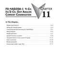
2.3 Pressure-Flow Curves
0
10
20
30
[gallons/min]
40
50
60
70
7.0
100
8000 rpm
Specific gravity = 1 g/cm
Viscosity = 0.7 cP
Liquid Temp.: 40C
6.0
7500 rpm
5.0
3
80
7000 rpm
60
4.0
Limits for up to 70C Liquid Temp.
[bar]
[psi]
3.0
40
6000 rpm
Limits for 90C Liquid Temp.
2.0
20
1.0
4000 rpm
5000 rpm
0.0
0
25
50
75
100
125
150
175
200
225
250
275
0
300
[liters/min]
Figure 6: Pressure/flow rate charts for aqueous liquids
(Measured with pump-head LPP-4000.1)
0
10
20
30
[gallons/min]
40
50
60
70
7.0
100
6.0
Specific gravity = 1.8 g/cm
Viscosity = 24 cP
Liquid Temp.: 20 C
5300 rpm
5.0
3
80
5000 rpm
[bar]
60
4.0
[psi]
3.0
40
4000 rpm
2.0
20
1.0
3000 rpm
0.0
0
25
50
75
100
125
150
175
200
225
250
275
0
300
[liters/min]
Figure 7: Pressure/flow rate charts for high density and viscosity liquids
(Measured with pump-head LPP-4000.1)
PL-4016-00, Rev02, DCO# 10-109
8
User Manual for BPS-4000
www.levitronix.com
2.4 NPSHr Curves
0
10
20
30
[gpm]
40
50
60
70
1.0
10
0.9
9
0.8
8
6000 rpm
0.7
7000 rpm
7
5000 rpm
8000 rpm
0.6
6
[bar]
[m]
7500 rpm
0.5
5
7000 rpm
Upper Axial Position
Limit of Impeller
6000 rpm
0.4
4
5000 rpm
Specific gravity = 1 g/cm
Viscosity = 0.7 cP
Liquid Temp.: 40 C
0.3
3
3
NPSHr Limitation Reasons:
- The min. absolute inlet pressure were the pump pressure is reduced by 3%
- Limitation resulting from the axial limit of the impeller
0.2
2
0.1
1
0.0
0
25
50
75
100
125
[lpm]
150
175
200
225
250
275
0
300
Figure 8: NPSHr curves
(Measured with pump-head LPP-4000.1)
2.5 General Environmental Conditions
Usage
Indoor (motor with pump head can be placed outdoor)
Altitude
Up to 2000m
Operating ambient temperature
0 to 40ºC
Storage ambient temperature
-20 to 80ºC
Operating humidity range (relative humidity)
15 – 95% (non condensing)
Storage humidity range (relative humidity)
15 – 95% (non condensing)
AC supply fluctuations
± 10% of nominal voltage
Transient over-voltages typically present on the mains supply
Surge immunity according to EN 61000-4-5
Pollution degree
2
Table 5: Environmental conditions for pump system
PL-4016-00, Rev02, DCO# 10-109
9
User Manual for BPS-4000
www.levitronix.com
2.6 Basic Dimensions of Main Components
Figure 9: Basic dimensions (in mm and [inch]) of LPM-4000.2 motor
Figure 10: Basic dimensions (in mm and [inch]) of LPM-4000.2 motor with LPP-4000.1 pump head
(for other configurations refer to according drawings)
PL-4016-00, Rev02, DCO# 10-109
10
User Manual for BPS-4000
www.levitronix.com
Figure 11: Basic dimensions (in mm and [inch]) LPM-4000 motor
with ACM-4000.1 & 3 Air Cooling Module
Figure 12: Basic dimensions (in mm and [inch]) LPM-4000 motor
with FCM-4000.1 Fan Cooling Module
PL-4016-00, Rev02, DCO# 10-109
11
User Manual for BPS-4000
www.levitronix.com
LPC-4000.1
LPC-4000.2
Figure 13: Basic dimensions (in mm and [inch]) of LPC-4000.1/2 controllers
PL-4016-00, Rev02, DCO# 10-109
12
User Manual for BPS-4000
www.levitronix.com
3 Engineering Information
3.1 Sealing and Material Concept
9
10
2
1
5
11
6
7
4
3
8
Figure 14: Sealing and material concept
System
Component
Pump-Head
LPP-4000.1
Motor
LPM-4000.2
Item
Materials
No
Description
1
Pump casing (lid and bottom)
PTFE
2
ANSI Flange rings 1.5” Inlet / 1” Outlet
PFA coated stainless steel
3
Pump Adapter and Fixation Ring
PP (+ GF 30%)
4
Static sealing O-ring of pump casing
Kalrez
5
8 screws for pump casing
PVDF
6
Impeller LPI-4000.1
ECTFE
7
Rotor magnet
Rare-earth material
8
8 screws for pump/motor mounting
PTFE coated stainless steel screws
9
Flat gasket for motor housing
FPM (= FKM)
10
Cable bushing
PVDF, cable jacket is FEP
11
Motor housing
ETFE coating, waterproof (IP-67)
Coils and electromagnetic circuit potted with
an epoxy compound (UL94 V0).
Table 6: Materials used in the LPM-4000.2 motor and LPP-4000.1 pump head
PL-4016-00, Rev02, DCO# 10-109
13
User Manual for BPS-4000
www.levitronix.com
3.2 Power Consumption
0
10
20
30
[gallons/min]
40
50
60
70
4500
8000 rpm
Specific gravity = 1 g/cm
Viscosity = ~ 0.7 cP
0
Liquid Temp.: 40 C
7500 rpm
4000
7000 rpm
3
3500
6000 rpm
3000
2500
[Watts]
5000 rpm
2000
1500
4000 rpm
1000
500
0
0
25
50
75
100
125
[liters/min]
150
175
200
225
250
275
300
275
300
Figure 15: Electrical power consumption for aqueous liquids
(Controller LPC-4000.x with pump-head LPP-4000.1)
0
10
20
30
[gallons/min]
40
50
60
70
4500
4000
Specific gravity = 1.8 g/cm
Viscosity = 24 cP
0
Liquid Temp.: 20 C
3
3500
5300 rpm
3000
5000 rpm
2500
4000 rpm
[Watts]
2000
1500
3000 rpm
1000
500
0
0
25
50
75
100
125
150
175
200
225
250
[liters/min]
Figure 16: Electrical power consumption for higher density/viscosity liquids
(Controller LPC-4000.x with pump-head LPP-4000.1)
PL-4016-00, Rev02, DCO# 10-109
14
User Manual for BPS-4000
www.levitronix.com
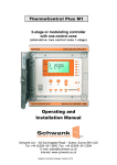
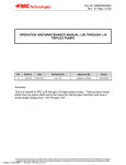
3.3 Temperature Monitoring
To avoid overheating of the system, the controller and motor temperatures are monitored. If the controller
temperature exceeds 70°C (158°F) or the motor temperature 90°C (194°F) for a duration of more than 10
minutes, the system goes into an error state and the pump stops. At 80°C (176 F) controller temperature or
100°C (212°F) motor temperature, the system stops immediately.
Start
Temperature
Monitoring
Start
Temperature
Monitoring
WARNING
YES
Temperature
> 70°C ?
NO
WARNING
YES
YES
ERROR
YES
YES
Temperature
higher than 70°C
for more than 10
minutes?
Temperature
> 80°C ?
ERROR
YES
Temperature
higher than 90°C
for more than 10
minutes?
NO
NO
Figure 17: Controller temp. monitoring
PL-4016-00, Rev02, DCO# 10-109
NO
YES
NO
ERROR
Temperature
> 90°C ?
ERROR
YES
Temperature
> 100°C ?
NO
Figure 18: Motor temp. monitoring
15
User Manual for BPS-4000
www.levitronix.com
3.4 Thermal Management
3.4.1 Motor Temperature
The motor temperature depends on the ambient and liquid temperature, as well as on the hydraulic
operation point and the characteristics (viscosity and density) of the liquid. Figure 19 illustrates the
temperature characteristics of the motor depending on these parameters. For higher liquid temperatures, and
hydraulic operating points active cooling is recommended for example with the Air Cooling Module ACM4000.1 (see Figure 21, Table 4, Figure 11) or the Fan Cooling Module FCM-4000.1 (see Figure 20, Table 4,
Figure 12).
0
10
95
20
[gpm]
30
40
50
60
8000 rpm
Absolute Temperature Limit
197
7500 rpm
85
70
7000 rpm
Recommended Operational Limit
177
75
5000 rpm
6000 rpm
4000 rpm
157
65
[F]
[ 0 C]
137
55
Ambient Temp = 25 C
Liquid Temp. = 25 C
Specific gravity = 1 g/cm3
Viscosity = 0.7 cP
Temp. Time Constant = ~5 hours
45
117
97
35
Aqueous Liquids
25
0
25
0
50
10
75
100
20
125
[lpm]
[gpm]
30
150
175
40
200
50
225
250
60
275
77
300
70
5300 rpm
95
Absolute Temperature Limit
197
85
Recommended Operational Limit
75
5000 rpm
177
4000 rpm
157
Ambient Temp = 25 C
Liquid Temp. = 25 C
3
Specific gravity = 1.8 g/cm
Viscosity = 24 cP
Temp. Time Constant = ~5 hours
65
[ 0 C]
55
[F]
137
3000 rpm
117
45
97
35
High Density/Viscosity Liquids
25
0
25
50
75
100
125
[lpm]
150
175
200
225
250
275
77
300
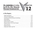
Figure 19: Temperature curves for the LPM-4000.2 motor @ 25 C liquid temperature
(Pumping with pump head LPP-4000.1, temperature is measured inside of the motor,
temperature of housing and sensor electronics is significantly below this temperature)
PL-4016-00, Rev02, DCO# 10-109
16
User Manual for BPS-4000
www.levitronix.com
0
10
20
[gpm]
30
40
50
60
70
95
Absolute Temperature Limit
197
85
Recommended Operational Limit
177
7000 rpm
8000 rpm
75
6000 rpm
7500 rpm
157
65
[F]
[ 0 C]
137
5000 rpm
55
117
45
Ambient Temp = 25 C
Liquid Temp. = 40 C
Specific gravity = 1 g/cm3
Viscosity = 0.7 cP
Temp. Time Constant: ~ 4 hours
35
Aqueous Liquids
Air cooling with FCM-4000.1
25
0
25
0
97
50
75
10
100
20
125
[lpm]
[gpm]
30
150
175
40
200
225
50
250
60
275
77
300
70
95
Absolute Temperature Limit
197
85
Recommended Operational Limit
5300 rpm
75
5000 rpm
177
4000 rpm
157
65
[F]
[ 0 C]
137
55
3000 rpm
Ambient Temp = 25 C
Liquid Temp. = 70 C
Specific gravity = 1.8 g/cm3
Viscosity = 24 cP
Temp. Time Constant: ~ 5 hours
45
117
97
35
Air cooling with FCM-4000.1
High Density/Viscosity/Temperature Liquids
25
0
25
50
75
100
125
[lpm]
150
175
200
225
250
275
77
300
Figure 20: Temperature curves of motor LPM-4000.2
with fan cooling module FCM-4000.1
(Pump head LPP-4000.1, Fan Cooling Module FCM-4000.1 at 25°C)
PL-4016-00, Rev02, DCO# 10-109
17
User Manual for BPS-4000
www.levitronix.com
0
10
20
[gpm]
30
40
50
60
70
95
197
Absolute Temperature Limit
85
Recommended Operational Limit
177
75
7500 rpm
8000 rpm
7000 rpm
6000 rpm
157
65
5000 rpm
[ 0 C]
[F]
137
55
Ambient Temp = 25 C
Liquid Temp. = 40C
Specific gravity = 1 g/cm3
Viscosity = 0.7 cP
45
117
Air cooling with ACM-4000.1
(Air Atenuator 0.5mm elevated)
35
97
0.9 bar, ~25 C air
Aqueous Liquids
25
0
25
0
50
75
10
100
20
125
[lpm]
[gpm]
30
150
175
40
200
50
225
250
60
275
77
300
70
95
Absolute Temperature Limit
197
85
Recommended Operational Limit
177
75
5000 rpm
4000 rpm
157
65
[F]
Ambient Temp = 25 C
Liquid Temp. = 70 C
Specific gravity = 1.8 g/cm3
Viscosity = 24 cP
Temp. Time Constant: ~ 5 hours
[ 0 C]
55
3000 rpm
137
Air cooling with ACM-4000.1
117
(Air Atenuator 0.5mm elevated)
45
0.9 bar, ~25 C air
97
35
High Density/Viscosity/Temperature Liquids
25
0
25
50
75
100
125
[lpm]
150
175
200
225
250
275
77
300
Figure 21: Temperature curves of motor LPM-4000.2
with air cooling module ACM-4000.1 & 3
(Pump head LPP-4000.1, Air Cooling Module ACM-4000.1 with 0.9 bar air at 25°C)
PL-4016-00, Rev02, DCO# 10-109
18
User Manual for BPS-4000
www.levitronix.com
77
87
97
107
117
127
[F]
137
147
157
167
177
187
95
197
85
177
No Active Cooling:
Temp. Gradiant = 0.41
75
[ 0 C]
157
65
[F]
137
Active Cooling with FCM-4000.1:
Temp. Gradiant = 0.36
55
Active Cooling with ACM-4000.1:
Cooling Pressure = 0.9 bar
Temp. Gradiant = 0.37
117
45
Ambient Temp = 25 C
Specific gravity = 1 g/cm3
Viscosity = 0.7 cP
35
97
Note: Gradiants measured for 6000 rpm / 100 l/min but
representative also for other flows and speeds
77
25
25
30
35
40
45
50
55
60
Liquid Temperature in [C]
65
70
75
80
85
90
Figure 22: Influence of liquid temperature on motor temperature
(Measurement at 6000 rpm 100 lpm, but gradients are representative for other operational points)
The above curves are measurements of the motor temperature at certain liquid and ambient temperatures.
Equation (Eq. 1) shows how to calculate the motor temperature for other liquid and ambient temperatures
based on these curves.
TM (TL , TA ) ≈ TM (TL = 250 C , TA = 250 C ) + (TL − 250 C ) ⋅
14444244443
see Figure 19
tg LM
{
+ (TA − 250 C )
see Figure 22
(Eq. 1)
TM
= Motor temperature
TL
= Liquid temperature
TA
=
tg LM
= Temperature gradient liquid/motor
Ambient temperature
In order to account for thermal variations (like ambient temperature, closed chemical cabinets or corners
without ventilations) and to not significantly reduce the MTBF of the motor it is recommended to keep about
10 to 20°C safety distance to the absolute thermal limit of the motor (90°C) when designing the thermal
concept of the pump system.
PL-4016-00, Rev02, DCO# 10-109
19
User Manual for BPS-4000
www.levitronix.com
3.4.2 Controller Temperature
Depending on the ambient temperature and the placement of the controller additional cooling may be
required (see Figure 23). To improve cooling of the controller, place the device into a moving air stream. If
the controller is mounted in a compact area or adjacent to additional heat sources (e.g. a 2nd controller)
ensure that there is sufficient ventilation.
0
10
20
[gpm]
30
40
50
60
70
167
75
Absolute Temperature Limit
70
157
65
147
Ambient temp. = 25 C
Specific gravity = 1 g/cm 3
Viscosity = 0.7 cP
PWM Drive = 5 kHz
PWM Bearing = 20 kHz
Fan: Temp. Controlled
Firmware: F1.48 Revision > 07
60
55
137
127
[ 0 C]
[F]
50
117
45
6000 rpm
7500 rpm
8000 rpm
107
7000 rpm
40
5000 rpm
35
97
4000 rpm
87
30
Aqueous Liquids
25
0
25
0
50
75
10
100
20
125
30
[lpm]
[gpm]
150
175
40
200
50
225
250
60
275
77
300
70
75
167
Absolute Temperature Limit
70
157
65
Ambient temp. = 25 C
Specific gravity = 1.8 g/cm3
Viscosity = 24 cP
PWM Drive = 5 kHz
PWM Bearing = 20 kHz
Fan: Temp. Controlled
Firmware: F1.48 Rev08
60
55
147
137
127
[°C]
[F]
50
5300 rpm
117
4000 rpm
5000 rpm
45
107
40
97
35
30
87
High Density/Viscosity Liquids
25
0
25
50
75
100
125
[lpm]
150
175
200
225
250
275
77
300
Figure 23: Temperature curves of controller LPC-4000 vs. flow and speed
(for pumping with pump head LPP-4000.1 and motor LPM-4000.2)
The above curves are measurements of the controller temperature at 25°C ambient. Equation (Eq. 2) shows
how to calculate the controller temperature for at other ambient temperatures based on this curve.
TC (TA ) ≈ TC (TA = 250 C ) + (TA − 250 C )
144244
3
see Figure 23
PL-4016-00, Rev02, DCO# 10-109
TC
= Controller temperature
TA
=
Ambient temperature
(Eq. 2)
20
User Manual for BPS-4000
www.levitronix.com
4 Installation
4.1 Electrical Installation of Controller
4.1.1 Overview
The LPC-4000 controllers have signal processor controlled power converters with six switched inverters for
the drive and the bearing windings of the motor. The signal processor allows precise control of pump speed
and impeller position. Figure 24 shows the interfaces of the standalone controller LPC-4000.1 with standalone and minimal PLC functions and Figure 25 the interfaces of the controller LPC-4000.2 with extended
PLC functions and USB interface for communication.
9 10
2
1
4
F1.25
8
3
11
5
7
6
Figure 24: Overview of the controller LPC-4000.1 for standalone operation
1
2
Interface (as labeled)
Description
“SENSORIC”
Position, field and temperature sensor signals from motor
1 Digital Input
- Galvanic isolation with optocoupler
- Switching voltage / current: minimal 5 V / 7 mA,
Typical 24 V / 16 mA, maximal 30 V / 20 mA
- Input resistance: RIN = 2.2 kΩ
1 Digital Output
- Galvanic isolation with relay
- Relay: 1A / 30VDC, 0.3A / 125 VAC
1 Analog Input
- Analog current input: 4 – 20 mA
- 450 Ohm shunt input
“USER INTERFACE”
3
“POWER OUTPUT”
Drive and bearing currents of the motor
4
“POWER INPUT”
DC power input
5
“Power on” Green LED
LED is on if supply voltage of signal electronics is present.
6
“Power Output not active”
Red LED
Red LED is off if the switched output stage of the controller is enabled. If the LED is on, the
bearing and drive coils of the motor carry no current.
7
“RESET” Button
Reset button of the controller stage. The button is sunk mounted and can be activated for
example with a small screw driver.
8
2-Digit Display “Speed”
Rotational speed display in 100rpm
9
“UP” Button
Button for speed increasing
10
“DOWN” Button
Button for speed decreasing
11
“Firmware” Label
Firmware version and revision number
Table 7: Description of interfaces of LPC-4000.1 controller
PL-4016-00, Rev02, DCO# 10-109
21
User Manual for BPS-4000
www.levitronix.com
3
1
5
4
2
6
8
7
Figure 25: Overview of the controller LPC-4000.2 for extended operation
1
2
Interface (as labeled)
Description
“SENSORIC”
Position, field and temperature sensor signals from motor.
“USER INTERFACE”
2 Analog Input
- Analog current input: 4 – 20 mA
- 450 Ohm shunt input
2 Analog Input
- Analog voltage input 0 – 10 V
- Direct connection, no galvanic isolation
- 7.8 kΩ input resistance
2 Analog Output
- Analog voltage output: 0 – 10 V
- - Direct connection, no galvanic isolation
- - Max. Output current: 2mA
4 Digital Input
-
4 Digital Output
- Galvanic isolation with relay
- Relay: 1A / 30VDC, 0.3A / 125 VAC
Galvanic isolation with optocoupler
Switching voltage / current: minimal 5 V / 7 mA,
Typical 24 V / 16 mA, maximal 30 V / 20 mA
Input resistance: RIN = 2.2 kΩ
3
“USB”
USB interface
4
“POWER OUTPUT”
Drive and bearing currents of the motor.
5
“POWER INPUT”
DC power input
6
“Power on” Green LED
LED is on if supply voltage of signal electronics is present.
7
“Power Output not active”
Red LED
LED is off if the switched output stage of the controller is enabled. If the LED is on, the
bearing and drive coils of the motor carry no current.
8
“RESET” Button
Reset button of the controller stage
Table 8: Description of interfaces of LPC-4000.2 controller
PL-4016-00, Rev02, DCO# 10-109
22
User Manual for BPS-4000
www.levitronix.com
4.1.2 General Installation Instructions
! WARNING
Hazardous voltage may be present.
Always isolate the electrical power supply before making or changing
connections to the unit. To remove the power it is recommended to use
an over-current or circuit breaker in close proximity to the controller.
! WARNING
Hazardous voltage may be present.
The controller housing must be properly grounded. Use the specified
screws on the feet of the controller housing.
! WARNING
Incorrect assembling of the “POWER INPUT” connector
Î short circuit possible.
Assure that the pin assignments of the “POWER INPUT” connector are
correct before it is plugged in.
1.
2.
3.
Connect the protective earth wire with a crimp-type end on the specified earth screw (see
Figure 26) on the feet of the controller (see also protective earth labels on controller).
Connect the two motor connectors (sensor and power) to the controller. Assure that the
“POWER OUTPUT” connector from the motor is correctly aligned with the connector of the
controller before it is plugged in.
Connect the AC power input connector. Make sure that the pin connections are correct
(see Figure 26):
- 1 x 200-240V (1-phase)
⇒
- 3 x 200-240V (3-phase)
⇒ L1 ,L2, L3, PE (lines can be switched), Y-voltage = 115 – 139V AC
L1 (⇒ L), L2 (⇒ N), PE (= Protective Earth)
2
- Minimum Wire Gauge = AWG 12 (cooper diameter = 2.052 mm, crosssection = 3.3 mm )
- External fuses of 25A / medium (m) in all power lines are recommended
4.
To secure the connectors, tighten all retaining screws.
Figure 26: AC power input and protective earth of LPC-4000 controller
PL-4016-00, Rev02, DCO# 10-109
23
User Manual for BPS-4000
www.levitronix.com
4.1.3 Electrical Installation of Controller LPC-4000.1 for Standalone Operation
For standalone operation the LPC-4000.1 is disabled when power is turned on. It can be enabled manually by
using the “UP” button on the display. If the controller shall be enabled automatically, when power is applied
the “ENABLE” pin on the “USER INTERFACE” connector (see Table 9) has to be active (typically 24V).
4.1.4 Electrical Installation of Controller LPC-4000.1 for Extended Operation
If the LPC-4000.1 shall to be controlled with external signals the “USER INTERFACE” can be used with the
PIN designations described in Table 9.
Pin Name
Connector
Pin Number
Analog In, (Signal)
5
Ground Analog In
6
Digital In, (Signal)
3
Ground Digital In
4
Digital Out
1
Ground Digital Out
2
Designation
Reference
Speed
Levels
Note
4..20 mA = 0..10000 rpm
Direct connection, no protection.
Galvanic isolation on the user
side is required.
Æ Speed Limit = 8000 rpm ≅ 16.8 mA
Æ Cut-off (min.) speed = 300 rpm
⇒ active
⇒ not active
Enable
24 V
0V
Status
Relay closed
Relay open
⇒ active, system on
⇒ not active, system off
Is needed to enable the system
with an external signal.
This signal indicates if the
system is active.
Table 9: Description of „USER INTERFACE“ connector
(Description is for firmware F1.25, for other configurations refer to alternate firmware documentation)
Figure 27: „USER INTERFACE“ connector
- Delivered with controller LPC-4000.1
- Supplier: PTR Messtechnik GmbH, Germany
- Connector Type: AK1550/06-3.81-GREEN
1
F1.25
6
Figure 28: Mounted “USER INTERFACE” connector and Pin numbering
PL-4016-00, Rev02, DCO# 10-109
24
User Manual for BPS-4000
www.levitronix.com
4.1.5 Installation of PLC Interface for Extended Controller LPC-4000.2
To operate the pump system with a PLC, a minimum set of two digital inputs and one analog input is needed.
The digital and analog outputs can be used to monitor the pump status and operating parameters.
CAUTION
The analog inputs and outputs are not galvanic isolated from the
controller electronics. To avoid ground loops and mal-functions, use
floating analog signals.
1. Detach the PLC connector from the controller
2. Connect the designated wires of a cable the pins of the detached connector according to
Table 10. Assignment and functions of the I/Os can be changed with the controller firmware
version (refer to according firmware documentation).
3. Connect the PLC connector (Figure 29) to the controller.
2
Connector Code
1
28
27
Figure 29: PLC connector
- Delivered with controller LPC-4000.2
- Supplier: Weidmüller
- Connector Type: B2L 3.5/28 SN BK BX
27
28
Connector Code
2
1
Figure 30: Mounted PLC connector and Pin numbering
PL-4016-00, Rev02, DCO# 10-109
25
User Manual for BPS-4000
www.levitronix.com
Connector
Pin
Wire name
Analog In1, (Signal)
Designation
17
Analog In2, (Signal)
20
Ground Analog In2
19
Note
4..20 mA = 0..10000 rpm (speed mode)
18
Ground Analog In1
Levels
Ref Value
(Current Input)
Æ Speed Limit = 8000 rpm ≅ 16.8Ma
Æ Cut-off (min.) speed = 300 rpm
4..20 mA = 0..100% (process mode)
Actual Process
Control Value
4..20 mA = 0..100%
(Current Input)
0..10 V = 0..10000 rpm
Analog In3, (Signal)
22
Ref Value
Ground Analog In3
21
(Voltage Input)
Analog In4, (Signal)
24
Actual Process
Control Value
Ground Analog In4
23
Analog Out1, (Signal)
26
Actual Speed
0..5 V = 0..10000 rpm
Analog Out2, (Signal)
28
Actual Process
Control Value
0..5 V = 0..100%
--
--
Reset
24 V
0V
⇒ active
⇒ not active
Com. Ground Analog Out
Digital In1, (Signal)
25, 27
1
Digital In2, (Signal)
4
3
Digital In3, (Signal)
6
Ground Digital In3
5
Digital In4, (Signal)
8
Ground Digital In4
7
Digital Out1
10
Ground Digital Out1
9
Digital Out2
12
Ground Digital Out2
11
Digital Out3
14
Ground Digital Out3
13
Digital Out4
16
Ground Digital Out4
15
- Default input settings:
Current inputs selected. Voltage
input can be selected with
EEPROM–editor in Service
Software (consult detailed firmware
specification F1.48 and Service
Software Manual with Doc.# PL2034-00)
0..10 V = 0..100 %
Direct connection, no protection.
Galvanic isolation on the user side
is required.
Resets error state
24 V
⇒ active
0V
⇒ not active
Switches between process mode
and speed mode
Enable
24 V
0V
⇒ active, system on
⇒ not active, system off
The Enable signal switches the
pump system on and off.
Not used
--
--
Status
Relay closed ⇒ active, system on
Relay open ⇒ not active, system off
This signal indicates the state of
the pump system.
Error
Relay closed ⇒ not active, system on
Relay open ⇒ active, system off
When active, the system drives the
impeller to zero rpm and shuts
down. With a reset pulse the
system can be re-initialized.
Warning
Relay closed ⇒ not active, system o.k.
Relay open ⇒ active, system not o.k.
The warning signal indicates if a
system fault has been detected.
The warning signal indicates a
system fault but the system does
not shut down
Trend Warning
Relay closed ⇒ warning active
Relay open ⇒ warning not active
Default setting: Relay closed if
trend warning is active. Can be
changed in EEPROM with Service
Software
Process mode
Ground Digital In2
- Direct connection, no protection.
Galvanic isolation on the user side
is required.
(Voltage Input)
2
Ground Digital In1
Æ Speed Limit = 9000 rpm ≅ 9 V
Æ Cut-off (min.) speed = 300 rpm
0..10 V mA = 0..100% (process mode)
- Grounds are internally connected
Table 10: Signals of the PLC connector for standard firmware F1.48
(For other configurations of PLC inputs and outputs refer to alternate firmware documentation.)
PL-4016-00, Rev02, DCO# 10-109
26
User Manual for BPS-4000
www.levitronix.com
4.2 Mechanical Installation of the Pump/Motor
4.2.1 Standard Installation Instructions and Information
!
WARNING
Overheating of the Motor Power and Extension Power Cable
To prevent an overheating of the motor power and extension power
cables, do not roll-up or install several motor power cables in the same
cable channel. This is has especially to be considered when long motor
power cables are used.
The motor can be fixed with four screws on the motor feet (see Figure 9)
As an alternative the motor can be mounted with 12 screws on the back (see Figure 9)
The motor can be mounted in either the horizontal or vertical position
Each motor is identified with a unique serial number. This serial number consists of a series of
6 digits were the 5th and the 6th digit representing the manufacturing year.
To prevent an overheating of > 90°C of the motor power cable in extension power cable,
please don’t roll-up or install several motor power cables in the same cable channel.
4.2.2 Installation of ATEX Motors
! WARNING
Motors for ATEX applications. Only specific types of motors LPM-4000
are classified for the use in ATEX Zone 2 classified locations. Refer to
the corresponding section in the manual.
! WARNING
Motors for ATEX applications. Use only, if necessary, the cooling
module ACM-4000.3 for motors installed in ATEX Zone 2 classified
locations. The use of the Fan Cooling Module FCM-4000.1 is not
allowed in ATEX applications.
An ATEX conform solution is needed for the motor cable to leave the ATEX area (see Figure 5). One option
is an ATEX certified cable sealing system as listed in Table 4 (see Pos. 8) and shown in Figure 2.
A protective earth wire shall be attached to the ATEX specific motor housing by using one of the eight M8
threads on the backside of the motor.
•
Remove one of the eight M8 screws on the backside of the motor
•
Use a crimp-type end together with a spacer sleeve to connect a earth wire
•
Attach the grounding wire with a M8 stainless steel screw to the motor according to
Figure 31: Attachment of a protective earth wire to the backside of the motor
PL-4016-00, Rev02, DCO# 10-109
27
User Manual for BPS-4000
www.levitronix.com
4.3 Mechanical Installation of the Controller
The controller can be fixed with four screws (for example M7) on the Controller feet (see
Figure 13)
If no forced air-cooling is used, mount the controller in upright position and assure that the
heat of the controller can dissipate. Avoid mounting the controller in a cabinet were heat is
stagnated and accumulated.
! WARNING
Hazardous voltage may be present.
In order to avoiding fluid spills shorting mains or other voltages within
the controller, place the controller in a spill protected environment (for
example protected electronic cabinets).
If explosive flammable gases are present, place the controller in an
explosion-proof cabinet.
CAUTION
Do not under any circumstances open the controller. Levitronix does
not assume responsibility for any damage, which occurs under such
circumstances.
PL-4016-00, Rev02, DCO# 10-109
28
User Manual for BPS-4000
www.levitronix.com
5 Operation
5.1 System Operation with LPC-4000.1 (Stand-Alone Version)
5.1.1 State Diagram of LPC-4000.1
The controller LPC-4000.1 allows stand-alone operation with manual speed setting (“Button Control Mode”)
as well as extended operation with analog speed setting (Analog Control Mode). Figure 32 shows the state
diagram which can be controlled with the manual buttons and the signals on the “USER INTERFACE”
connector. The operation mode can be chosen by pressing the “UP” and “DOWN” buttons simultaneously
during 5 seconds. For the standard firmware F1.25 default setting ex factory is “Button Control Mode”.
Reset Button
Power On
Factory default setting
ButtonControl saved
in EEPROM
AnalogControl saved
in EEPROM
OFF
ButtonControl
!
Error
OFF
AnalogControl
Press both
for 5 sec
Enable
input = 24V
System Error
Enable
input = 0V
Enable
input = 0V
Enable
input = 24V
If Speed
@ 0 RPM
!
Press up
for 1 sec
Error
Ref. Speed
UP
Press up
for 2 sec
Press down
for 1 sec
ON
(Speed Mode)
ButtonControl
Ref. Speed
DOWN
Ref.-Speed set
to stored value*
Press down
for 2 sec
ON
(Speed Mode)
AnalogControl
Press both
for 5 sec
Button Control Mode
Ref.-Speed set by
analog input
Analog Control Mode
!
Error
!
Error
Figure 32: State diagram for operation with LPC-4000.1 controller
(Description is for firmware F1.25, for other configurations refer to alternate firmware documentation)
PL-4016-00, Rev02, DCO# 10-109
29
User Manual for BPS-4000
www.levitronix.com
5.1.2 Standalone Operation (Button Control Mode)
When applying power the system defaults into the “Button Control Mode” and goes into the
status “OFF ButtonControl” according to Figure 32. Levitation is disabled and the display
indicates “OF”.
Levitation can be enable by pressing the “UP” button during 1 second (display shortly
indicates “ON”) or by activating (typically 24V) the “ENABLE” pin on the “USER INTERFACE”
connector (see Table 9). The system goes then into the status “ON Button Control” and is
running at the speed which is stored in the EEPROM.
The speed can be changed by pressing accordingly the “UP” and “DOWN” buttons.
As long as the digits on the display are blinking the set speed is shown. As soon as blinking
stops the actual speed is shown and the set-speed is stored in the EEPROM of the controller
after about 2 seconds.
The system can be disabled by pressing the “DOWN” button until 0 rpm is achieved. Pressing
further 1 second the “DOWN” button the system disables levitation and shows “OF” on the
display. The system can also be disabled by deactivating (0 V) the “ENABLE” pin on the
“USER INTERFACE” connector (see Table 9). Before disabling the system the speed is
automatically reduced to 0 rpm and the impeller is properly touched down without grinding the
wall.
In case of an error the “RESET” button (see Table 7) can be used to restart the system or the
power can be switch off and on. For detailed error analysis the codes described in Table 11
are shown on the two digit display (blinking between “Er” and the according code number).
Figure 33: User Panel of LPC-4000.1
PL-4016-00, Rev02, DCO# 10-109
30
User Manual for BPS-4000
www.levitronix.com
5.1.3 Extended Operation (“Analog Control Mode”)
In order to be able to control the pump with external signals (PLC) the mode “Analog Control
Mode” has to be set with the display buttons. The “UP” and “Down” buttons have to be pressed
simultaneously during 5 seconds. The display should feedback the change by blinking between
the stored speed value and “An”. The chosen mode is then stored in the EEPROM of the
controller.
The system and levitation can be enabled/disabled with the digital input on the “USER
INTERFACE” connector (see Table 9). When disabling the running system, the speed is
automatically reduced to 0 rpm and the impeller is smoothly touched down without grinding the
wall.
The speed can be set with an analog signal on the “USER INTERFACE” connector according to
Table 9. It is strongly recommended to use galvanic separated signal values
For monitoring purposes a digital output on the “USER INTERFACE” connector (see Table 9)
indicates an error. In case of an error the codes described in Table 11 are displayed (blinking
between “An” and the according code number)
5.1.4 Error Display on the Integrated Panel
Error
Source
Errors
Error Code
on Display
Motor
No Motor
Er 01
Motor
Motor cable (power wires) not connected to controller
Er 02
Motor
Motor cable (sensor wires) not connected to controller
Er 03
Motor
No Rotor
Er 04
Controller
Short circuit
Er 05
Controller
Over current in the bearing coils
Er 06
Controller
Over current in the drive coils
Er 07
DC-Link voltage out of range
Æ Voltage range for monitoring: 243 – 378 V DC
Controller
Æ If the voltage is out of range the system starts to reduce the speed. When reaching 0 rpm and
the voltage is still out of range an Error is generated.
Er 08
Æ In case the voltage is again within the range during speed reduction the system switches to
normal operation and no Error is generated.
Controller
Communication problems EEPROM Controller
Er 09
Motor
Communication problems EEPROM Motor
Er 10
Controller
Controller temp. over 80°C or more than 10 minutes above 70°C
Er 11
Motor
Motor temp. over 100°Cor more than 10 minutes above 90°C
Er 12
Dry running of pump circuit:
Pump
Æ Pump keeps running on reduced speed (5000 rpm)
Æ The system accelerates to the original speed value when the pump is refilled with liquid
Æ Note that the speed is only reduced during dry running if the pump speed was ≥ 6000 rpm.
Blinking
dots on
display
Table 11: Errors and warnings with indication on display of LPC-4000.1
- In case of an error the system can only be restarted with a reset or a power supply restart
- Standard firmware is F1.25
- For other configurations of error codes refer to alternate controller or firmware documentation
PL-4016-00, Rev02, DCO# 10-109
31
User Manual for BPS-4000
www.levitronix.com
5.2 System Operation with Controller LPC-4000.2 (PLC version)
5.2.1 State Diagram of the PLC Interface
Power On
OFF
Reset: active
Status : not active
Enable: active
Reset: not active
Enable: not active
ON
ERROR
(Speed Control Mode)
Enable: not active
Internal Error
Status : Active
Error : not active
Process Mode:
not active
Status : not active
Error : active
Process Mode:
active
ON
(Process Control
Mode)
Internal Error
Status : Active
Error : not active
Figure 34: PLC interface state diagram for standard firmware F1.48
(For other configurations refer to alternate firmware documentation)
PL-4016-00, Rev02, DCO# 10-109
32
User Manual for BPS-4000
www.levitronix.com
State “Off”:
The pump system is switched off and the motor has no power. In this state, Levitronix Service Software has
full control.
State “ON” (speed control mode):
The pump system is switched ON and the impeller is rotating with the referenced speed. The motor has
electrical power when in this state.
State “ON” (process control mode):
The pump system is switched ON and the impeller speed is controlled in order to get the referenced
flow/pressure. The motor has electrical power when in this state.
State “Error”:
If an error according to Table 12 occurs in the pump system, the system defaults to the Error state. The
designated digital output on the PLC Interface is activated. The pump system is switched OFF. By activating
the “Reset” input the system gets back to the “Off” state.
Error Source
Errors
Effect on Designated
Digital Output of the PLC
Motor
No rotor
Error = relay open
Motor
Temperature over 100°C
Error = relay open
Motor
Temp. was higher than 90°C for more than 10 minutes.
Error = relay open
Motor
Temperature more than 90°C
Warning = relay open
Motor
No motor temperature signal
Warning = relay open
Motor
Motor power cable not connected with controller
Error = relay open
Motor
Motor sensor cable not connected with controller
Error = relay open
Controller
Over-current
Error = relay open
Controller
Power channel interrupted
Error = relay open
Controller
Temperature over 80°C
Error = relay open
Controller
Temp. was higher than 70°C for more than 10 minutes.
Error = relay open
DC link (supply voltage) out of range (< 243 or > 378 V DC)
Controller
Controller
If the voltage is out of range the system starts to reduce the speed and a
warning is generated. When reaching 0 rpm and the voltage is still out of
range the system is disabled and an error is generated. In case the voltage
is again within the range during speed reduction the system switches to
normal operation and no Error is generated.
Temperature over 70°C
Error = relay open
Warning = relay open
Dry Running Detection
Æ Pump keeps running on reduced speed (5000 rpm)
Controller
Æ The system accelerates to the set speed value when the pump is
refilled with liquid
Warning = relay open
Æ Note that the speed is only reduced during dry running if the pump
speed was ≥ 6000 rpm
Table 12: Errors and warnings with indication on PLC interface for standard firmware F1.48
(For other configurations refer to alternate firmware documentation)
PL-4016-00, Rev02, DCO# 10-109
33
User Manual for BPS-4000
www.levitronix.com
5.3 System Operation for ATEX Applications
5.3.1 General Safety Requirements
Specific precautions may be considered while using the pump system in potential explosive gas
atmospheres according to ATEX category 3G/3D (Zone 2 and 22).
The user shall prevent priming issues during normal pump operation. Especially precautions have to be
considered during installing and maintenance operations to prevent the occurrence of combustible
atmospheres.
The user shall prevent electrostatic charging of the system at cleaning processes by using dry cleaning cloth.
User shall use wet cleaning rags to avoid issues with charging during a cleaning process.
CAUTION
Precautions have to be considered to prevent priming issues during
installation operation and maintenance of the pump head / motor.
! WARNING
Operational Temperature T5
Maximum allowed pump liquid temperature is 90°C / 194°F for the use
in ATEX Zone2 applications.
! WARNING
Do not operate the pump against closed valves
Refer to the corresponding section in the manual.
5.3.2 Control of Motor Casing Temperature
To avoid high motor casing temperatures and to control the temperature sensor operation the following steps
shall be considered:
For operation with the LPC-4000.2 controller the “Digital Out 3” of the PLC connector (see Table 10 ) shall be
monitored for warnings during operation in order to check if the communication to the temperature sensor is
established. If “Digital Out 3” is active (this output indicates warnings caused by various sources, inter alia
communication problems with the motor) the pump system may be checked for correct operation. The motor
temperature readings can be monitored via the Levitronix Service Software.
For standalone operation with the LPC-2000.1 controller the display shall be checked periodically for error
messages according to Table 11 (see error Er10 = “Communication problems EEPROM Motor”).
Additionally the motor casing temperature shall be periodically measured and compared to the internal motor
temperature readings. This comparison measurement checks potential drifts of the internal motor
temperature sensor. Adhesive foil made of aluminum can be used to improve the thermal junction between
motor casing and the external temperature sensor.
CAUTION
To prevent possible drifts of the motor temperature sensor the sensor shall be
checked and compared to an external measurement of the motor casing
temperature. This comparison measurement should be carried out at
maintenance procedures every 12 month. The internal temperature sensor
should not vary more than -10 °C to the external measurements. Positive drifts
are not considered as critical.
PL-4016-00, Rev02, DCO# 10-109
34
User Manual for BPS-4000
www.levitronix.com
6 Inspection and Maintenance
6.1 Replacement Interval of the Impeller
The impeller has a limited lifetime depending on the chemical type, concentration and temperature of the
fluid which is pumped. Therefore a preventive periodical exchange of the impeller is recommended. Contact
the Levitronix Technical Service Department (see Section 8) for further information on replacement times.
6.2 Impeller Replacement Procedure
6.2.1 Preparation
Before starting the impeller replacement procedure
the parts and tools illustrated in Figure 36 should
be prepared. Impeller exchange kits, which contain
these parts are available at Levitronix. Figure 36
lists the standard components. For special configurations contact Levitronix. Please verify that
you have the right types of impellers, O-rings and
screws.
MagLev Motor
! WARNING
The impeller could splash TOXIC or
CORROSIVE CHEMICALS because of the
strong magnetic forces. Flush the pump housing
before opening it.
! WARNING
O-Ring
Adapter Ring
Pump Casing Bottom
Impeller
Pump Casing Lid
Semi Fixation rings
HARMFULL CHEMICALS may be present.
Skin contact and toxic gases may be hazardous
to your health. Wear safety gloves and other
appropriate safety equipment.
Figure 35: Explosion view of pump head with motor
! CAUTION
O-Ring
Impeller
The rotating impeller could cause injury. Do not
run the pump system when opening the pump
head.
CAUTION
Pump casing screws
Pump motor screws
Figure 36: components for impeller replacement
The following warnings and cautions should be
read carefully before starting the replacement of
the impeller.
PL-4016-00, Rev02, DCO# 10-109
Pay attention to the magnetic forces when
handling the impeller. The attraction of magnetic
parts and particles should be avoided in order to
keep the impeller and the pump head clean and
free of contamination.
35
User Manual for BPS-4000
www.levitronix.com
6.2.2 Instructions for Replacement
1. Power down the pump system and remove
the AC supply voltage. It is necessary to let
cool down to a workable temperature (near
ambient) before the impeller can be exchanged.
4. Unscrew the 8 screws on the both semi
fixation rings.
2. Unscrew the 8 PTFE coated stainless steel
screws of the adapter ring after the motor is
cooled down.
3. Remove the complete pump head from the
motor. Make sure that the motor is fixed
sufficiently to withstand the coupling forces of
the impeller magnet. Do not use the inlet or
outlet fitting to pull away the pump head as
they are maid of PTFE with limited strength.
PL-4016-00, Rev02, DCO# 10-109
5. Twist the semi fixation rings together to
release the snap clips and separate it from the
pump head. Alternative use 2 screwdriver to lift
the snap clips.
36
User Manual for BPS-4000
www.levitronix.com
6. Press the adapter ring down.
! CAUTION
Pay attention to the magnetic forces when
handling the impeller. The attraction of
magnetic parts and particles should be
avoided in order to keep the impeller and the
pump head clean and free of contamination.
Avoid magnetic and metal parts within a radius
of about 1 meter.
8. Replace the impeller. If necessary, remove the
existing O-Ring and press the new O-Ring into
the lid of the pump casing.
7. Remove the pump housing lid with the sealing
ring. Remove the impeller. Inspect the wet
area of the pump head carefully. In case of
material damage, also replace the pump
casing.
CAUTION
Use always the specified O-Ring type. If
necessary, consult the Levitronix Technical
Service Department. Do NOT twist or roll the
O-Ring as this may cause leaking to occur.
9. Press the lid with the O-ring flush into the
bottom of the pump casing.
PL-4016-00, Rev02, DCO# 10-109
37
User Manual for BPS-4000
www.levitronix.com
10.Press the pump casing into the adapter ring
and add both fixation rings.
11.Tighten the 8 PVDF screws crosswise and
symmetric regular on the semi fixation rings.
The screws should not be used to press the
lid with the O-ring into the bottom of the pump
casing. Do not apply too much torque. The
torque specification is:
Maximum torque for pump casing screws:
PVDF M10: 100Ncm
12.Insert the pump casing to the motor by placing
the bottom of the pump head on the side of
the protecting cup and move it afterwards to
the center until the pump-head locks in. Do
not directly insert the pump head to the center
of the motor as the fingers could be squeezed
by the magnetic forces.
Mount the pump head with the 8 stainless steel
screws crosswise and symmetric regular on the
Motor. Do not apply too much torque. The torque
specification is:
Maximum torque for pump motor screws:
PTFE coated stainless steel M10: 120Ncm
13.
14.Start the system and check if the impeller is
rotating properly and the pump head doesn’t
leak.
15.If the pump head leaks, check and make sure
that the lid and the O-Ring are properly
pressed into the bottom of the pump casing. It
may be necessary to change the O-Ring if it
has been damaged.
CAUTION
Take care of your fingers. Hold the pump head
on the outer side and not on the bottom
because of risk to get the fingers squeezed.
OK!
PL-4016-00, Rev02, DCO# 10-109
38
User Manual for BPS-4000
www.levitronix.com
7 Troubleshooting
7.1 Troubleshooting for Operation with Controller LPC-4000.1
For troubleshooting and failure analysis with the stand-alone controller LPC-4000.1 the following procedure
is recommended:
- Check the status of the LEDs. The specific LEDs are described in Table 7
- Use the ERROR codes on the display. The specific error codes are described in Table 11
- A digital output on the “USER INTERFACE” connector (“Status”) indicates if the system is active.
However, the source of an error cannot be identified by this signal
7.2 Troubleshooting for Operation with Controller LPC-4000.2
The integrated PLC provides a Warning and an Error signals according to Table 12. However, the source of
error cannot be identified by these signals.
For more detailed analysis the Levitronix® Service Software can be used with a PC and a USB interface to
the controller.
7.3 Troubleshooting with Service Software
The Levitronix® Service Software allows communication with the pump system in connection with a PC and
a USB interface. The software can be used for performing detailed troubleshooting. For usage of the Service
Software refer to the Service Software User Manual (Document #: PL-2034-00), which is available in the
download section on the Levitronix Web-page or contact the Levitronix® Technical Service Department (see
under Section 8).
Note: the Service Software can not be used with the standalone controller LPC-4000.1.
PL-4016-00, Rev02, DCO# 10-109
39
User Manual for BPS-4000
www.levitronix.com
8 Technical Support
For troubleshooting, support and detailed technical information contact Levitronix® Technical Service
Department:
Levitronix®
Technical Service Department
Technoparkstr. 1
CH-8005 Zurich
Switzerland
Phone for US:
888-569 07 18
Phone for outside US:
+1 888-569 07 18
E-Mail:
[email protected]
PL-4016-00, Rev02, DCO# 10-109
40
User Manual for BPS-4000
www.levitronix.com
9 Appendix
9.1 Regulatory Status
9.1.1 CE Marking
The Bearingless Centrifugal Pump System BPS-4000, in its various configurations, is in conformity with the
essential requirements of the Machinery Directive 2006/42/EC (according to Annex II under A) and the
essential requirements of the Low Voltage Directive 2006/95/EC.
The following particular harmonized standards of the EMC Directive 2004/108/EC are tested and confirmed
at a certified laboratory (Hochschule für Technik Zurich, Technoparkstr.1, CH-8005 Zürich, Swiss
Certification No.: STS404):
EN61000-6-2
EN61000-6-4
Generic standards, Immunity for industrial environments
Generic standards, Emission standard for industrial environments
Additionally the following standards have been used as a guideline for the design and validation:
EN61010-1
EN60990
EN809
EN12162
Safety requirements for electrical equipment: used as general design guide for controller and motor.
Procedure for measurements of leakage currents: measured according to picture 4.
Pumps for Fluids: basic requirements are followed.
Procedure for hydrostatic pressure testing in fluid pumps: max. pressure testing.
9.1.2 ATEX Marking
Specific motors together with the pump head of the BPS-4000 pump system are in conformity with the
requirements of the Directive 94/9/EC. The following standards are tested and confirmed at a certified
laboratory (Electrosuisse, Switzerland, CH-8320 Fehraltorf, Swiss testing No. STS 001, conformity statement
SEV 10 ATEX 0131).
EN60079-0
EN60079-15
EN61241-0
EN61241-1
Electrical apparatus for explosive gas atmospheres. General requirements.
Electrical Apparatus for explosive gas atmospheres. Construction, test and marking of type of
protection, “n” electrical apparatus.
Electrical apparatus for use in the presence of combustible dust. General requirements
Electrical apparatus for use in the presence of combustible dust. Protection by enclosure tD
The Levitronix Ex motors are marked clearly and in accordance to the ATEX Directive. The protection EX nA
means non sparking electrical apparatus.
II 3G Ex nA IIC T5
II 3D Ex tD A22 IP67 T100°C
Classification:
Category 3GD (Zone 2 for Gas and Zone 22 for Dust)
Explosion Groups:
Group IIA: Propane (IPA), Methane, Aceton, Acetaldehyde
Group IIB: Ethylene, Ethylenglycol
Group IIC: Acetylene, Hydrogen (not carbon disulphide)
Thermal Classification:
Thermal classification of motor is T5 (< 100 C = 212 F) for maximum full-load operating
0
0
temperature at a maximum liquid temperature of 90 C / 194 F.
UL Correspondence:
ATEX listing corresponds to UL hazardous location Class 1 Division 2.
0
PL-4016-00, Rev02, DCO# 10-109
0
41
User Manual for BPS-4000
www.levitronix.com
9.2 Symbols and Signal Words
Symbol /
Signal Word
Description
Type
Source
DANGER
Indication of an imminently hazardous situation that, if
not avoided, will result in death or severe injury.
Limited to the most extreme situation
Signal word
SEMI S1-0701
WARNING
Indication of a potentially hazardous situation which, if
not avoided, could result in death or severe injury.
Signal word
SEMI S1-0701
CAUTION
Indication of potentially hazardous situations which, if
not avoided, could result in moderate or minor injury.
Also alert against unsafe practice.
Without safety alert indication of hazardous situation
which, if not avoided, could result in property damage.
Signal word
SEMI S1-0701
Safety alert for “Warning” and “Caution”
Safety alert
SEMI S1-0701
Safety alert for “Danger”
Safety alert
SEMI S1-0701
Refer to manual
ISO 3864
Toxic material, poison
Hazard identification
IEC 61310
Corrosive material, corrosion
Hazard identification
IEC 61310
Cut/sever hand, sharp object
Hazard identification
ANSI Z535.3
Strong magnetic field
Hazard identification
SEMI S1-0701
Danger: electricity, electrical hazard
Hazard identification
IEC 61310,
ISO 3864
Wear safety gloves
Hazard avoidance
Mandatory action
IEC 61310
Wear face shield
Hazard avoidance
Mandatory action
SEMI S1-0701
Unplug power line
Hazard avoidance
Mandatory action
SEMI S1-0701
No pacemakers
Hazard avoidance
Prohibition
SEMI S1-0701
Used for hazard
identificat. in warnings
--
!
!
Caution (refer to accompanying documents)
(is used on article labels for reference to manual)
ATEX Logo
Table 13: Safety symbols and signal words
PL-4016-00, Rev02, DCO# 10-109
42