1
HAMGSM133
5.
Overview
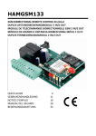
Refer to the illustrations on page 2 of this manual.
1
2
O1
O2
LD1
LD2
LD3
LD4
LD5
U1
U2
6.
power supply
USB interface (optional)*
3
4
output 1
output 2
I1
I2
SIM card (not included)
antenna connector
* HAMGSM133/USB, not included
input 1
input 2
U3
mini USB connector
relay 1 active
relay 2 active
input 1 active (logical condition reached)
input 2 active (logical condition reached)
GSM network connection status
transmit LED
receive LED
Installation
•
When applicable install the USB interface HAMGSM133/USB [2] (not included). The mini USB connector
must be on top.
•
Insert a valid SIM card [3]. Make sure the PIN code of the SIM card is disabled. Use a normal mobile
phone for this.
•
Connect the antenna to the antenna connector [4].
•
Make all necessary connections (I1, I2, O1, O2). Only connect a SELV (Safety Extra Low Voltage) load
to the outputs. Tension applied to the contacts of each relay must not exceed 60Vdc; switching current
on the relays must not exceed 10A (short peak). The maximum tension applied to the digital inputs is
32Vdc.
•
Connect the power supply [1] (not included). Use a stabilized current-limited power supply (not
included) providing 9~32Vdc and at least 500mA current (able to deal with absorption peaks of 1A).
Note that the centre tip is positive.
•
Close the housing (not included).
7.
Introduction
•
The HAMGSM133 is a bidirectional remote control module capable of remotely controlling two relays
(in monostable or bistable mode) through the use of special SMS commands sent from any mobile
phone.
•
Memory for up to 8 telephone numbers to which SMS and/or ringtones can be sent when input status
changes (master list).
•
It is also possible to use the HAMGSM133 as a gate control receiver controlled by up to 200 entered
phone numbers (gate control list).
•
To facilitate programming, it is possible to connect a USB interface module and manage the device via
PC through downloadable software. This module must be purchased separately; order code
HAMGSM133/USB.
8.
Configuration
There are 3 ways to set up the device:
8.1
•
through call (only at start-up)
•
through SMS
•
through USB (USB interface required, not included).
Through call (only at start-up)
When the device is supplied with power, “LD5” will immediately flash at 1 Hz frequency. The HAMGSM133 will
try to connect to the GSM network. When connected, “LD5” will briefly flash every 2 seconds. After the system
initialization (which may take several seconds), the device alternately illuminates yellow LEDs “LD3” and “LD4”
to indicate the “configuration call” on hold mode for 3 minutes. If during this time the unit receives a call, it
stores the caller’s number (to which reply SMS will be sent) in the first memory location and LD3 and LD4 turn
off.
V. 02 – 15/05/2012
7
©Velleman nv