1
ENERGRID INVERTER 3300
Operating and
installation manual
(1-28)
Bedienungsanleitung
(29- 56)
TENESOL
12-14 Allée du Levant
69890 LA TOUR DE SALVAGNY
France
Téléphone: +33 (0)4 78 48 88 50
Fax: +33 (0)4 78 19 44 83
www.tenesol.com
Operating and installation manual
Table of Contents
EI 3300
1
Scope of delivery
2
2
General / Notes on safety
2
3
Introduction
3
4
System
4.1
Data evaluation and communication
4.2
Technical structure of the solar power inverter
4.3
Equipment overview
5
Installation
3
4
4
5
6
6
Installation of equipment
6.1
Installation location
6.2
Minimum requirements
6.3
Lightning protection
6.4
Installation
6.5
Ambient temperature
6.6
Network connection
6.7
PV generator connection
6.7.1 Solar inverter range
6.7.2 Efficieny
6.8
Interface connection RS485 (EIA485)
6.9
Electrical connection and operational startup
6.10
LED operation and fault display
6
6
6
7
7
8
8
9
10
10
11
12
13
7
Operating concept
7.1
The display
7.2
Navigation in the display
7.3
Main menu
7.3.1 Submenu N (Now)
7.3.2 Submenu D (Day)
7.3.3 Submenu W (Week)
7.3.4 Submenu M (Month)
7.3.5 Submenu Y (Year)
7.3.6 Submenu T (Total)
7.3.7 Submenu S (Set-up)
14
14
14
14
16
16
17
17
17
18
18
8
Diagnostics and data evaluation
Malfunction rectification
Display messages
19
19
19
Technical Data
21
10
Appendix
10.1
Connection examples
10.2
Accessories 22
22
24
11
Glossary
25
12
Certificates
27
8.1
8.2
9
Operating and installation manual
Rev: 5
Page of 28
1
Scope of delivery
EI 3300
• Solar Inverter
• Mounting plate
• Operating and installation manual
• AC connector
2
General / Notes on safety
Dear Customer,
Congratulations on the purchase of this technically high-quality solar inverter.
These directions will help you become familiar with this product.
Please consider the safety regulations as well (VDE, VDEW, BGFE, technical connection conditions
for local utility company). Careful handling with your product will contribute to its service life durability and reliability. These are significant prerequisites for outstanding results.
Please consider the following notes on safety:
• During operation of electrical devices, certain parts are under dangerous voltage.
• Inappropriate handling can lead to physical injury and material damage!
• Adhere to the installation regulations.
• Installation and operational startup work may be implemented only through qualified electrical experts
• Repair work on the device may be carried out by the manufacturer only.
• Please consider all points in the operating and installation manual!
• Isolate the device from the mains network and the PV modules before you carry out any work
on it.
• As a result of very high temperatures, the device surface area can become hot.
• Sufficient cooling is necessary.
• Do not bring the device into operation without covering the DC connectors.
Do not open the Solar Inverter. No user serviceable parts. Risk of electrical hazard and invalidated warranty.
Dangeorous voltage present for 5 minutes after disconnecting all sources of
power.
This manual accompanies our equipment for use by the end users.
The technical instructions and illustrations contained in this manual are to be treated as confidential and no part may be reproduced without the prior written permission of Tenesol Service engineers and end users may not divulge the information contained
herein or use this manual for purposes other than those strictly connected with correct use of the equipment. All information and
specifications are subject to change without notice.
Operating and installation manual
Rev: 5
Page of 28
3
Introduction
EI 3300
With this device you have acquired a solar inverter for the mains connection of photovoltaic systems. This solar inverter is characterized by its advanced housing design and state-of-the-art radio
frequency technology, which enable the highest levels of efficiency.
The solar inverter includes series monitoring units, such as ENS, display and RS485 (EIA485)
interface.
The inverter is usable indoors and outdoors. It fulfills the directives of the VDEW (Union of German
Electrical Power Stations) for parallel operation of power generation plants on low-voltage network
of regional electrical utility companies.
The function of the ENS (automatic isolation point for in-plant generation systems) stipulates compliance with the specifications of DIN VDE 0126-1-1 and compliance with the low-voltage guideline.
These are declared through the attached GS-Innova character and the CE mark (CE Certification
- see Appendix).
In the following technical description, the precise functions are explained to the installer, as well
as the user, which are required for the installation, operational startup and handling of the solar
inverter.
4
System
The content of renewable energy with respect to overall power consumption worldwide is increasing annually by approx. 25%. The reason for this rise can be primarily attributed to the constantly
increasing demand for power, the increasing interest in environmentally friendly technologies, as
well as the increasing costs of non-renewable energy.
By the use of renewable energy sources, the earth‘s atmosphere can be enormously relieved of
increases in CO2 and other harmful gases which result from power generation.
The solar inverter converts direct current from the solar cells into alternating current. This enables
you to feed your self-produced solar energy into the public mains.
Thanks to efficient MPP tracking, maximum capacity utilization of the solar energy plant is ensured
even in case of a misty and clouded over sky.
The string concept means that PV modules are always connected in series (in a string) and/or that
strings with the same voltage are connected in parallel to the solar inverter with the aim of significantly reducing the photovoltaic system’s cabling requirements.
The fact that the modules are connected in strings also means that the photovoltaic system
can be perfectly matched to the solar inverter’s input voltage range.
Operating and installation manual
Rev: 5
Page of 28
EI 3300
4.1
Data evaluation and communication
The integrated data display, processing and communication of the device enables easy operation
of the solar inverter. Monitoring of the operational status and signaling of operational failures are
capable of being called up over the device display. The data interfaces enable the downloading of
data which can be evaluated with the aid of a PC system and thus guarantees continuous recording
of operating data.
The best way of accessing this functionality is via the available accessories (e.g. Energrid Data);
and a complete monitoring of the solar inverter is ensured.
The read-out of the data over the integrated interface and the display is possible only in solar operation.
4.2
Technical structure of the solar power inverter
A potential isolation of the solar inverter from the mains network is achieved through a radio frequency converter with integrated transformer. The photovoltaic voltage is adjusted so that the maximum power output of the PV modules is also achieved with different solar irradiation levels and
temperatures (MPP-Tracking).
The MPP range of the solar inverter is between 150 V and 450 V. This facilitates the use of PV
modules by a variety of manufacturers. Measures must be taken to ensure that the maximum noload voltage of 540 V is never exceeded. Please note that the maximum no-load voltage will occur
at the lowest temperatures anticipated. You will find more detailed information about temperature
dependency in the data sheet for the PV modules.
The device’s power consumption is kept to a minimum.
The high-quality aluminum casing corresponds to Protection Type IP65 (water-jet-proof and dustproof) and is protected against weathering processes by surface refinement. The cooling characteristic profile is designed so that operation of the inverter is possible with ambient temperatures
from -25°C to +70°C.
A cooling characteristic profile is used for the removal of the power dissipation caused through
the voltage conversion. An internal temperature control protects the device against too high temperatures in the interior of the solar inverter. In case of high ambient temperatures, the maximum
transferable power is limited (see diagram under 6.5).
The solar inverter is controlled by microcontrollers, which also realize the communication of the
interfaces and the display.
Two independent and redundant microcontrollers control the monitoring of the network, which is
consistent with the feed-in directives of VDEW and DIN 0126-1-1 (ENS). This enables an installation of the solar inverter in the in-house mains network.
Operator protection requirements are met by electrically isolating the mains from the PV module
and by implementing measures for PV module insulation monitoring in respect of the PE (protective
earth). Relevant standards concerning the electromagnetic compatibility (EMC) and the security
system are fulfilled.
The solar inverter is functional in network parallel operation exclusively. An automatically-acting
isolation point, which was accepted by a certification agency, guarantees secure disconnection in
case of circuit isolation or interruptions in power supply and avoids isolated operation.
Operating and installation manual
Rev: 5
Page of 28
EI 3300
The equipment provided for the disconnection is a so-called „automatic isolation for in-plant generation systems of nominal power ≤ 4.6 kVA, with single-phase parallel feed-in over solar inverter into
the mains network of the public supply“.
4.3
Equipment overview
(5)
(4)
(3)
(1)
(2)
(1) Covering for DC connectors and connections for PV modules
(2) Mains connection
(3) Interface connection RS485 (EIA485)
(4) Display for status display and keyboard for operation
(5) 3 Light-emitting diodes for operating status display
Covering for DC connectors must be fixed during operation!
Operating and installation manual
Rev: 5
Page of 28
5
EI 3300
Installation
Installation and commissioning must only be carried out by qualified electrical experts!
The prescribed safety regulations, the technical interface conditions (TAB 2000), as well as the VDE
specification, are to be complied with.
In order to be able to carry out an energy measurement, a meter must be attached between the
network feed-in point and the solar inverter (in accordance with the VDEW directive concerning „Inplant generation systems on the low-voltage mains network“).
By means of the integrated ENS, the function of the prescribed section switch is fulfilled in accordance with the VDEW directive concerning „In-plant generation systems on the low-voltage mains
network“. In case of ENS not being present, precautions must be provided through a section switch
for the disconnection from the network, in accordance with above directive.
Caution: The secondary short-circuit current rating is increased at the transfer connection point to
the public electricity supply system by the nominal current of the connected solar inverter.
6
Installation of equipment
The solar inverter must be installed at a location where it is not exposed to direct rain and direct
sunshine. An increased ambient temperature can reduce the efficiency of the PV system.
6.1
Installation location
• Install the device on a non-inflammable support base
• Avoid installation on resonating bodies (light construction walls etc.)
• Installation is possible both indoors and protected outdoor area
• Noise generation possible (avoid installation in the residential area)
• Ensure legibility of the LED‘s and the display (read-off angle / installation height)
6.2
Minimum requirements
• Free convection around the solar inverter must not be impaired
• Leave an open space of approx. 50 cm for air circulation around the device
• The network impedance at the supply terminal is to be considered (cable length, cable cross-
section)
• The prescribed installation position is to be adhered to (vertical)
• Unused DC connectors (Tyco) must be shut through sealing connectors.
50 cm
Wall
Wall
50 cm
50 cm
50 cm
Operating and installation manual
Rev: 5
Page of 28
EI 3300
Minimum 50 cm
6.3
Lightning protection
The risk posed by lightning strikes is reduced by means of a single-point earthing system. With this
kind of system, all earthing lines terminate at the same point. As a general rule, this point will be
the earthing arrangement that was installed by the electric utility company when the building was
wired.
6.4
Installation
You should employ the delivered mounting plate for problem-free installation of the solar inverter.
The attachment on the wall should be implemented with adequate hexagonal bolts or socket bolts.
Mount the wall bracket so that the solar inverter only has to be simply attached at a later time. After
that, the device is to be bolted on securely.
Assembly instructions
1.
Mount the mounting plate. You can employ the mounting plate as a drill template for marking the positions for the boreholes.
2.
Place the solar inverter onto the mounting plate.
3.
Fasten the supplied mounting nuts and washers on the threaded bolt intended for secu-
ring the device.
4.
Check the solar inverter for secure seating.
358
350
396.9
290
t=2,5
Mounting
plate
38
90
2.5
Ø1
12
6.5
12
Locking screw
150
319.5
390 ± 0.3
410 ± 0.5
Operating and installation manual
Rev: 5
Page of 28
EI 3300
6.5
Ambient temperature
The solar inverter can be operated in an ambient temperature between -25°C to +70°C.
The following diagram illustrates how the power supplied by the solar inverter is reduced automatically in accordance with ambient temperature.
The device should be installed in a well-ventilated, cool and dry location.
3600
3300
3000
2700
AC Power (W)
2400
2100
1800
1500
1200
900
600
300
0
30.0
40.0
50.0
60.0
70.0
80.0
Ambient temperature (°C)
PV Voltage 150V
PV Voltage 270V
PV Voltage 400V
6.6
Network connection
The network (AC output) is connected over a Wieland RST25i3S AC connector. You can find the
correct allocation on the screw-type terminal connection of the connector. The solar inverter must
be connected to the network over a three-core line (L, N, PE). The connected AC line must be
switched potential-free before the disconnection or the insertion of the AC connector.
The connection to the Wieland AC connector must be implemented with a flexible line and a conductor cross section of min. 2.5 mm² to max. 4.0 mm².
Between the mains and each inverter, there must be an automatic cutout with a nominal current of
25 A and a type B tripping characteristic in the phase cable (L). Care must also be taken to ensure
that any lightning arresters are selected appropriately.
Please note the cable length and the cable cross-section.
An insulation fault on the DC side (or earth fault) is detected before the solar inverter is connected
to the mains. In this way the power supply connection is prevented in case of insulation faults. All
safety equipment meets the requirement for single-fault tolerance.
The AC connector is protected from unintentional disconnection by a clip mechanism which can be
released with a screwdriver.
Operating and installation manual
Rev: 5
Page of 28
EI 3300
6.7
PV generator connection
Before the photovoltaic system is connected, the cover must be removed from the DC connector
and the polarity of the PV voltage at the Tyco connectors must be checked to ensure that it is correct. The connectors are colour-coded red (+) and blue (-).
The connection of the PV module is implemented using a Tyco Solarlok connector, where the minus
pole is located on the connector upper row and the positive pole on the connector lower row.
Connectors cannot be incorrectly connected.
Please ensure the following at all times:
• that there is never any risk of anyone coming into contact with the solar inverter connection terminals, due to the risk of dangerous voltages across them.
• that the inputs of the solar inverter must not have any reference to the ground potential. This
reference leads to instant disconnection of the device.
• that under no circumstances the PV modules are disconnected from the solar inverter under
load. If a disconnection should be necessary, first switch the network off so that the solar inverter cannot absorb any further power.
The solar inverter is equipped with the connector connection system from the company Tyco. The
maximum input voltage is 540 Vdc.
Cable
coupler
polarity
Wire size
2.5 mm2
(AWG 14)
Plus
coupler
•
•
Minus
coupler
Plus
coupler
Minus
coupler
Wire size
4.0 mm2
(AWG 12)
Wire size
6.0 mm2
(AWG 10)
Female cable Female cable Tyco
coupler
coupler
Order
Plus coded
Minus coded number
•
1394462-1
•
•
•
Plus
coupler
Minus
coupler
Operating and installation manual
Rev: 5
•
1394462-3
•
•
•
1394462-2
•
1394462-4
1394462-5
•
1394462-6
Page of 28
EI 3300
6.7.1
Solar inverter range
Energrid 3300
Please consider the following
curve diagram
of the der
solar
inverter:
Maximalelimit
Ausgangsleistung
als Funktion
Eingangsspannung
3500
3400
3300
Output
power (W) / W
Ausgangsleistung
3200
3100
3000
2900
2800
2700
2600
2500
125
150
175
200
225
250
275
300
325
350
375
400
425
450
Spannung der PV Module / V
Voltage of PV Modules (V)
6.7.2
Efficieny
The best efficiency of the solar inverter is obtained at input voltages > 250 V.
98,0
96,0
Efficiency (%)
94,0
92,0
90,0
88,0
86,0
84,0
82,0
80,0
0
500
1000
1500
2000
2500
3000
3500
Output power (W)
PV Voltage 150V
Operating and installation manual
Rev: 5
PV Voltage 275V
PV Voltage 400V
Page 10 of 28
EI 3300
6.8
Interface connection RS485 (EIA485)
The interfaces not used must always be closed off. In case of utilization of an interface, only the
counterpart fitting the interface connector is to be employed.
Mating connector supplier HARTING Deutschland GmbH & Co. KG (Postal Code 2451, D - 32381
Minden; www.harting.com)
Order designation: 09 45 145 1510, Cable Manager Blue IP67 Push-Pull Data Plug
09 45 145 1500, Cable Manager White IP67 Push-Pull Data Plug
Power
Controller
BFS
Communication
ENS
Operating- and System Control
DC
String A
String C
String D
DC
DC
MPPTracker
-
Isolation
-
-
-
DC-Bus
String B
Booster
-
Public
mains
~
AC
DC
Solar Inverter
-
~
~
~
~
230 V - House connection line
RS485 (EIA485) - Connection
Energrid Data
Operating and installation manual
Rev: 5
Page 11 of 28
EI 3300
6.9
Electrical connection and operational startup
The solar inverter is delivered in an operable status.
The electrical connection is implemented on this solar inverter using the connector contacts which
are attached to the casing. In no case must the device be opened!
In order to connect the device electrically, the following procedures must be followed:
1. DC connection: Start by connecting the PV module strings to the Tyco connectors on the solar inverter.
2. Install the cover for the Tyco connectors.
3. AC connection: Next, connect the AC connector to the solar inverter and then to the mains.
4. Before switching on the power, check all feeders and connections one last time.
5. Close automatic cutouts on the input side.
6. In case of sufficient PV voltage (UPV > 150 V), the solar inverter now goes into the start-up mode.
Any Tyco connectors not being used must be sealed using the plugs supplied with
the inverter!
Operating and installation manual
Rev: 5
Page 12 of 28
EI 3300
6.10
LED operation and fault display
Three light-emitting diodes (LED‘s), which display the operational state of the solar power inverter,
are attached on the front:
Operation
(A)
Earth Fault (B)
Failure
(C)
• LED (A), green: „Operation“ displays the operational state.
• LED (B), red: „Earth Fault“ displays an insula-
tion resistance fault on the DC side. Additio-
nal output of “Error 508” on the display.
• LED (C), yellow: „Failure“ displays existing faults internally or externally and whether the network feed-in operation has been inter-
rupted.
LED-Status
Operational state
Explanation
green: <Off>
red: <Off>
yellow: <Off>
Night disconnection.
The input voltage (UPV) is lower than 100 V.
The inverter is completely disconnected from the
grid. All internal supply voltages are switched off.
green: <On>
red: <On>
yellow: <On>
Initialization.
Input voltages:
UPV: 100V to 150 V
(self test ongoing).
green: <Flashes>
red: <Off>
yellow: <Off>
Network monitoring.
Starting conditions are tested:
UPV: > 150V.
green: <On>
red: <Off>
yellow: <Off>
Feed-in operation.
Normal operational state:
UPV: 125V to 540V.
green: <Off/Flashes>
red: <On/Off>
yellow: <On>
Equipment fault.
Internal or external fault (interrupted feed).
See also display messages!
Operating and installation manual
Rev: 5
Page 13 of 28
7
EI 3300
Operating concept
7.1
The display
The delivery of the solar inverter is implemented ready for operation. No presetting adjustments are
therefore necessary for the user.
The display on the device indicates different information. The enter keys are used for the adjustment
of the device and for the call-up of information. The indicated measuring data can deviate with a
tolerance of up to 8%.
Key (A):
(A)
(B)
(C)
ESC
(D)
For changing from the menu
items into the main menu
and for exiting the set-up
menu.
Key (B) and (C): For scrolling in the individual
menu items and/or carrying
out adjustments in the set-up
menu.
Key (D):
ENTER key for changing into
the menu levels and for input
acknowledgement in the
set-up menu.
7.2
Navigation in the display
Lighting of the display
Through pressing the ENTER key in automatic operation, the display lighting is implemented. If no
key should be activated within 30 seconds, the display lighting automatically goes out. The set-up
menu enables selection between continuous or automatic lighting. Through pressing the ENTER
key, the display lighting is switched on again.
7.3
Main menu
The main menu consists of 7 menu items which are subdivided into submenus:
• Menu N (Now)
• Menu D (Day)
• Menu W (Week)
• Menu M (Month)
• Menu Y (Year)
• Menu T (Total)
• Menu S (Set-up)
Handling of the menu items:
You can scroll the main menu by activating the selector keys
.
Press the ENTER key to select the submenus. In order to exit the menus again, activate the ESC
key.
Operating and installation manual
Rev: 5
Page 14 of 28
EI 3300
ESC
ENTER
1. Menu - N
Now (act. Data)
Sub Menu
2. Menu - D
Day Statistic
Sub Menu
3. Menu - W
Week Statistic
Sub Menu
4. Menu - M
Month-Statistic
Sub Menu
5. Menu - Y
Year Statistic
Sub Menu
6. Menu - T
Total Statistic
Sub Menu
7. Menu - S
Setup Inverter
Sub Menu
Operating and installation manual
Rev: 5
Page 15 of 28
EI 3300
7.3.1
Submenu N (Now)
This menu item displays the instantaneous values.
ESC
ENTER
1. Menu - N
Now (act. Data)
1. N -> AC-Power
xxxx W
Display of the
active output power
2. N -> AC-Voltage
xxx V
Display of the active
output voltage
3. N -> AC-Current
xx.x A
Display of the active
output current
4. N -> AC-Frequency
xx.xx Hz
Display of the active
mains frequency
5. N -> Solar-Voltage
xxx V
Display of the active
solar cell voltage
6. N -> Solar-Current
xx.x A
Display of the active
solar cell current
7. N -> Time
HH:MM:SS
Display of the
current time
8. N -> Date
WD, DD.MM.YYYY
Display of the
current date
7.3.2
Submenu D (Day)
This menu item displays the daily values for the mains feed.
ESC
ENTER
1. Menu - D
Day Statistic
1. D -> Energy
xxxx Wh
Display of the daily
energy gain
2. D -> Revenue
xxxxx.xx Euro
Display of the daily revenue
3. D -> AC-Power-Max.
xxxx W
Display of the daily
maximum power
4. D -> AC-Volt.-Max.
xxx V
Display of the daily max.
input voltage
5. D -> AC-Volt.-Min.
xxx V
Display of the daily min.
input voltage
6. D -> AC-Curr-Max.
xx.x A
Display of the daily
maximum current
7. D -> AC-Freq.-Max.
xx.xx Hz
Display of the daily
maximum frequency
8. D -> AC-Freq.-Min.
xx.xx Hz
Display of the daily
minimum frequency
9. D -> Runtime
HHH:MM
Display of the daily operating
time of the solar inverter
Operating and installation manual
Rev: 5
Page 16 of 28
EI 3300
7.3.3
Submenu W (Week)
This menu item displays the average values of the current week.
ESC
ENTER
1. Menu - W
Week Statistic
1. W -> Energy
xxxx kWh
Display of the weekly
energy gain
2. W -> Revenue
xxxxx.xx Euro
Display of the weekly revenue
3. W -> Runtime
HHH:MM
Display of the weekly operating
time of the solar inverter
7.3.4
Submenu M (Month)
This menu item displays the average values of the current month.
ESC
ENTER
1. Menu - M
Month Statistic
1. M -> Energy
xxxx kWh
Display of the monthly
energy gain
2. M -> Revenue
xxxxx.xx Euro
Display of the monthly revenue
3. M -> Runtime
HHH:MM
Display of the monthly operating
time of the solar inverter
7.3.5
Submenu Y (Year)
This menu item displays the average values of the current year.
ESC
ENTER
1. Menu - Y
Year Statistic
1. Y -> Energy
xxxx kWh
Display of the annual
energy gain
2. Y -> Revenue
xxxxx.xx Euro
Display of the annual revenue
3. Y -> Runtime
HHH:MM
Display of the annual operating
time of the solar inverter
Operating and installation manual
Rev: 5
Page 17 of 28
EI 3300
7.3.6
Submenu T (Total)
This menu item displays the values of the mains feed since initial startup of the solar inverter.
ESC
ENTER
1. Menu - T
Total Statistic
1. T -> Energy
xxxx kWh
Display of the total
energy gain
2. T -> Revenue
xxxxx.xx Euro
Display of the total
revenue
3. T -> Sol.-Vol.-Max.
xxx V
Display of the total max.
solar cell voltage
4. T -> Sol.-Cur.-Max.
xx.x A
Display of the total solar
cell current
5. T -> Sol.-Pow.-Max.
xxxx W
Display of the total solar
cell power
6. T -> Isolation-Max.
xxxx kOhm
Display of the largest
insulation resistance
7. T -> Isolation-Min.
xxxx kOhm
Display of the smallest
insulation resistance
8. T -> Runtime
HHH:MM
Display of the total operating
time of the solar inverter
7.3.7
Submenu S (Set-up)
This menu item is used for changing the presettings of the solar inverter.
ESC
ENTER
1. Menu - S
Setup Inverter
1. S -> LCD-Contrast
2. S -> LCD-Backlight
3. S -> Menu-Mode
4. S -> Cash
5. S -> ID-Number
6. S -> Baudrate
0 ... 9
Auto / On
Now ... Setup
xx.xx Euro
001 ... 254
2400 ... 38400
7. S -> Time
HH:MM:SS
8. S -> Date
WD, DD.MM.YYYY
Adjustment of the brightness of
the LCD display between 0 ... 9
Adjustment of the LCD
background lighting
Selection of the start menu
on restart of the device
Input of the kWh price
Input of the ID number of the solar inverter
Adjustment of the baud rate
between 2400 ... 38400 Baud
Adjustment of the internal clock
Adjustment of the date
Display of the version number of
module assemblies:
9. S -> Firmware
AC-Control x.xx
AC monitoring board
DC-Control x.xx
DC monitoring board
ENS Master x.xx
ENS board (for ENS version only)
ENS Slave x.xx
ENS board (for ENS version only)
Display x.xx
Operating and installation manual
Rev: 5
Display
Page 18 of 28
8
EI 3300
Diagnostics and data evaluation
8.1
Malfunction rectification
The solar inverter is provided with an automatic diagnostics system which independently identifies
certain faults and which can make them visible externally on the display.
Troubleshooting in the field
In principle, it is always worth attempting a reset by reinitialising the solar inverter whenever an error
message appears on the display.
To reset the device, proceed as follows:
1. Isolate the solar inverter from the mains (open the circuit-breaker).
2. Disconnect the solar cells from the inverter.
3. Reconnect the solar cells to the inverter.
4. Reconnect the mains (close the circuit-breaker).
In the field, the first step is to scan for potential fault causes.
The information on the display can be used for troubleshooting.
Current values in the N menu
AC Voltage -> Display of current output voltage -> Voltage limiting values
AC Frequency -> Display of current mains frequency -> Frequency limiting values
Solar Voltage -> Display of current voltage of the solar modules
8.2
Display messages
Display message
Characteristic behavior
Elimination
AC frequency failure
Mains frequency overshooting
or undershooting specified limit
range.
- Check the mains frequency via the
display in the N menu.
AC voltage failure
Mains voltage overshooting or undershooting specified limit range.
- Check the mains voltage via the
display in the N menu.
- In the event of a lack of voltage, check the
circuit-breaker on the mains side.
DC injection failure
DC component of input-side alternating current is too high.
- If the fault persists after the device has been
reset, please inform your service technician.
Error # 101
Display communication is faulty.
- If the fault persists after the device has been
reset, please inform your service technician.
Operating and installation manual
Rev: 5
Page 19 of 28
EI 3300
Error # 301
Internal communication error
or hardware fault.
- If the fault persists after the device has been
reset, please inform your service technician.
Error # 302, over
temperature
The device trips and reverts
to mains input mode once
the temperature has dropped
again.
- Check the installation site (no direct
sunlight, air circulation).
Error # 508
Insulation resistance fault on
the DC side. The red LED
lights up.
- You must check the insulation resistance on the
DC side of the solar modules.
MOV warning error
Internal varistor at the DC
input is defective.
- Although you can, in theory, carry on using the
solar inverter, the varistors should be replaced at
the earliest opportunity. This will involve returning
the device.
Relay error
One of the ENS output relays
is faulty/defective.
- The solar inverter is defective.
- Return the device.
Self test ongoing
Initialisation of solar inverter
on start-up.
- Normal function with a solar cell voltage of
between 100 V and 150 V.
- Verification of the operating state of the LEDs.
Solar power too low
Insufficient solar power.
- Solar cell voltage less than 150 V.
- Check the solar cell voltage via the display in the
N menu.
Solar voltage too low
The PV generator voltage is
between 100 V and 150 V.
- Insufficient insolation.
- Check the solar cell voltage via the display in the
N menu.
Synchronize to AC
Checks mains voltage and
mains frequency for mains
input mode. The green LED
flashes to indicate that the
check is in progress.
- Check the mains voltage and frequency via the
display in the N menu.
- Normal function before input mode.
Please follow the instructions above before contacting your service technician!
Operating and installation manual
Rev: 5
Page 20 of 28
9
EI 3300
Technical Data
Input (DC)
Output (AC)
Max. recommended PV power
4000 Wc
Nominal power
3300 W AC
Nominal power
3630 W DC
Max. power
3485 W AC
Nominal voltage
270 V DC
Nominal voltage
230 V AC
Voltage range
125 ... 540 V DC
Voltage range
196 ... 253 V AC
MPP range
150 ... 450 V DC
Nominal current
14,4 A AC
Full power MPP range
150 ... 450 V DC
Max. current
17,0 A AC
Nominal current
13.0 A DC
Nominal frequency
50 Hz
Max. current
24.0 A DC
Frequency range
47.5 ... 50.2 Hz /
(4)
49.0 ... 51.0 Hz
Stand-by power
< 0.2 W
Distortion factor
<3%
General Specification
(1), (2)
(3)
Mechanical Design
Efficiency max.
96.0 %
Efficiency EU / California
94.8 %
Operating temperature range
-25 ... +70 °C
Weight
21.5 kg
Storage temperature range
-25 ... +80 °C
Cooling
Natural convection
Humidity
0 ... 98 %
AC connector
Wieland RST25i3S
DC connector
4 Tyco Solarlok
Certification
Protection class
Size
W x L x D (mm)
410 x 410 x 180
Norms
IP65
ENS
VDE 0126-1-1
(3)
RD1663/2000
(4)
Safety class
1
Switch-off parameter adjustable
Yes
Insulation monitoring
Yes
EN61000-4-2
Overload characteristic
Current limiting;
power limiting
EN61000-4-3
Safety
EN60950-1
EN61000-4-4
Draft IEC 62109-1
EN61000-4-5
Draft IEC 62109-2
EN61000-4-6
IEC 62103
EN61000-4-8
EN 50178
EN61000-3-2
EMI / EMC
EN55022 Class B
(1) Version EOE46010002
196 V ... 253 V
Full power 3300 W AC
184 V ... 196 V
Reduced power 3100 W AC
253 V ... 264 V
Possible for 10 minutes only (according to VDE 0126-1-1)
(2) Version EOE46010003
196 V ... 253 V
Full power 3300 W AC
---
Reduced power 3100 W AC
---
Possible for 10 minutes only (according to VDE 0126-1-1)
(3) Version EOE46010002, according to VDE 0126-1-1
(4) Version EOE46010003, according to RD1663/2000
Operating and installation manual
Rev: 5
Page 21 of 28
EI 3300
10
Appendix
10.1
Connection examples
Individual in-plant generation system in parallel operation without isolated
operation possibility, single-phase feed with ENS.
Low-voltage network ~ 400 / 230 V
House connection line
House connection box
VNB
Owner boundary
Customer
Measurement unit
(1) Meter for power consumption
(2) Meter for power feed-in
with back stop in each case
Z
(2)
Z
(1)
Remark: A meter can also be employed
which registers both energy directions separately
~ 400 / 230 V
Electric circuit distributor
Switching equipment
ENS with voltage and frequency monitoring,
as well as network impedance measurement
Consumer
equipment of
the customer
Photovoltaic
generator with
power inverter
max. 4.6 kVA
~
=
Short-circuit protection
Overload protection
Individual in-plant generation system in parallel operation without isolated
operation possibility, single-phase feed with ENS, separate feed.
Low-voltage network ~ 400 / 230 V
House connection line
House connection box
VNB
Owner boundary
Customer
Z
(3)
Z
(2)
Z
(1)
Remark: A meter can also be
employed which registers both energy
directions separately.
(3) Meter for power take-off of the
customer system
~ 400 / 230 V
Electric circuit distributor
Switching equipment
ENS with voltage and frequency
monitoring, as well as network impedance
measurement
Consumer equipment
of the customer
Photovoltaic
generator with
power inverter
max. 4.6 kVA
Operating and installation manual
Rev: 5
Measurement unit
(1) Meter for power consumption
(2) Meter for power feed-in
with back stop in each case
~
=
Short-circuit protection
Overload protection
Page 22 of 28
EI 3300
Connector pin assignment RS485 (EIA485)
Pin
8
Top View
1
1
2
3
4
5
6
7
8
Not used
Not used
Not used
GND (RS485)
TERM (RS485)
RX_B (RS485)
TX_A (RS485)
Not used
When several devices are connected in series and the total length of the data line measures 2 m or
more, the following options are available for terminating the RS485 (EIA485) interface:
+5V
Not used
0R
TX_A
Pin 7
RX_B
Pin 6
0R
Not used
100 ... 150
Ohm, 0,25W
121R
TERM
GND
+5V
Not used
0R
TX_A
RX_B
Pin 6
0R
Not used
121R
TERM
GND
Operating and installation manual
Rev: 5
Pin 5
Page 23 of 28
EI 3300
10.2
Accessories
Harting Push Pull system cable RJ45, 8-core
System cable for Industrial Ethernet
Technical data
Protection class
IP 65/67 (when plugged in)
Cable used
4x2, twisted pair, shielded, PiMF
Connector types used
RJ45 PushPull
Wiring
8-pin, 1:1
Transmission properties
Category 6, Class E up to 250 MHz in acc. with
ISO/IEC 11 801:2002
Transmission speed
10/100/1000 Mbit/s
Sheath
Green PVC, ø 6.8 mm
Working temperature range
- 10°C to + 70°C
Benefits
Standardised Push Pull interface for IP65/67,
user-friendly and reliable, highly compact
Standard cables:
We have defined certain standard cable lengths ranging from 1 to 50 metres and longer; please
contact us for codes and prices.
Operating and installation manual
Rev: 5
Page 24 of 28
11
Glossary
EI 3300
AC
Abbreviation for „Alternating Current“.
Bridge circuit
Electrical circuit with which the voltage is measured between two impedances, each switched in
series. This can be drawn as a bridge in a circuit diagram.
CE
With the CE identification code, the manufacturer confirms the conformity of the product with the
valid EC Guideline and compliance with the significant requirements stipulated therein.
DC
Abbreviation for „Direct Current“.
EMC
The Electro-Magnetic Compatibility (EMC) concerns the technical and legal basics of the mutual
influencing of electrical devices through electromagnetic fields caused by them in electrical engineering.
ENS
This is a unit for network monitoring with assigned switching elements (ENS) and is an automatic
isolation point for small power generation systems (to 30 kWp).
Initialization
Under initialization (cf. English to initialize) is understood the part of the loading process of a program, in which the storage space required for the execution (e.g. variable, code, buffers ...) for the
program is reserved and is filled with initial values.
Electric utility company
An electric utility company is generally defined as a company which produces electricity and distributes it via the public mains.
Microcontroller
Microcontrollers are single-chip computer systems with which almost all components are integrated.
MPP
The Maximum Power Point is the point of the current-voltage diagram of a solar cell at which the
largest power can be tapped off, i.e. the point at which the product of current and voltage has its
maximum value.
Nominal power
Nominal power is the maximum permissible continuous power output indicated by the manufacturer
for a device or a system. Usually the device is also optimized so that the efficiency is at its maximum
in case of operation with nominal power.
Nominal current
Nominal current is the absorbed current in case of electrical devices if the device is supplied with
the nominal voltage and yields its so-called nominal power.
Operating and installation manual
Rev: 5
Page 25 of 28
EI 3300
PE
In electric systems and cables a protective earth conductor is frequently employed. This is also
called grounding wire, protective grounding device, soil, grounding or PE (English „protective
earth“).
Photovoltaics (abbr.: PV)
The conversion of solar energy into electrical energy.
The name is composed of the component parts: Photos - the Greek word for light - and Volta
- after Alessandro Volta, a pioneer in electrical research.
Potential isolation
No conductive connection between two component parts.
Power dissipation
Power dissipation is designated as the difference between absorbed power and power of a device or process yielded in the required form. Power dissipation is released mainly as heat.
Power inverter
(Also inverter) is an electrical device which converts DC direct voltage into AC voltage and/or
direct current into alternating current.
RS485 (EIA485)
Differential voltage interface on which the genuine signal is transmitted on one core and the
negated (or negative) signal on the other core.
Separate network system
Energy supply equipment which is completely independent of an interconnected network.
Solar cell
Solar cells are large-surface photodiodes which convert light energy (generally sunlight) into
electrical energy. This comes about by utilization of the photoelectric effect (photovoltaics).
Solar module
(Also solar generator) is an application of photovoltaics and converts radiation energy into electrical energy. As the most important modular element, it includes several solar cells.
String
Designates a group of electrical solar modules switched in series.
String power inverter (power inverter concept)
The PV generator is divided up into individual strings which feed into the network over their own
string power inverters in each case. In this way, the installation is considerably facilitated and the
gain decrease, which can arise from the installation or from different shading conditions of the
solar modules, is considerably reduced.
VDE
Verband der Elektrotechnik, Elektronik und Informationstechnik e. V.
(Association of Electrical Engineering, Electronics and Information Technology).
VDEW
Union of German Electrical Power Stations.
Operating and installation manual
Rev: 5
Page 26 of 28
12
EI 3300
Certificates
EC DECLARATION OF CONFORMITY
TENESOL
12-14, allée du Levant
69890 LA TOUR DE SALVAGNY
France
We:
Declare that the following Photovoltaic Inverter types:
Energrid Inverter 3300
Solar inverter for Grid operation
The product described above in the form as delivered is in conformity with the provisions of the following
European Directives:
89/336/EWG
Council Directive on the approximation of the laws of the Member States relating to electromagnetic
compatibility (amended by 91/263/EEC, 92/31/EEC, 93/68/EEC and 93/97/EEC)
73/23/EWG
Council Directive on the approximation of the laws of the Member States related to electrical
equipment designed for use within certain voltage limits (amended by 93/68/EEC)
Conformity to the Directives is assured through the application of the following standards:
Reference number
Edition
Reference number
Edition
Safet y
EN 60950-1
Draft IEC 62109-1
Draft IEC 62109-2
IEC 62103
EN 50178
2005(2nd Ed.); 2006
2003
2005
2003
1998
I m m unity
EN 61000-4-2
EN 61000-4-3
EN 61000-4-4
EN 61000-4-5
EN 61000-4-6
1995; A2: 2001
2002
1995; A2: 2001
1995; A2: 2001
1996; A2: 2001
EM C
EN 55022
EN 61000-6.3
EN 61000-6-4
2004-09 (Class B)
2001; A11 : 2004
2001
Harm onics / Flicker
EN 61000-3-2
EN 61000-3-3
2000; A2: 2005
1995; A1 : 2001
S p ain m arket versio n
RD 1663/2000
2000
Germ an m arket version
DIN VDE V 0126-1-1
2006-02
The Solar inverters Energrid Inverter 3300 does also comply with the VDEW Publication:
“Richtlinie für Anschluss und Parallelbetrieb von Eigenerzeugungsanlagen am Niederspannungsnetz“
Place, Date of declaration:
LA TOUR DE SALVAGNY, 19 October 2006
Guy OLIVIER
"--²&%6-&7"/5
-"5063%&4"-7"(/:'3"/$&
5ÏM
t'BY
UFOFTPM!UFOFTPMGS tXXXUFOFTPMGS
Technical Director
Groupe TENESOL
4"BVDBQJUBMEF&4*3&/3$4-:0/
4*3&5/¡57"'3"1&,
Operating and installation manual
Rev: 5
Page 27 of 28
EI 3300
Innova Product Service GmbH, A Bureau Veritas Company
Gewerbestr. 28
87600 Kaufbeuren
Germany
+ 49 (0) 8341 96660-0
[email protected]
Certificate of compliance
Applicant:
TENESOL
12-14 allée du Levant
69890 LA TOUR DE SALVAGNY
France
Product:
Automatic disconnection device between a
generator and the public low-voltage grid
Model:
EI 3300
Use in accordance with regulations:
Automatic disconnection device with single-phase mains surveillance in accordance
with DIN V VDE V 0126-1-1:2006-02 for photovoltaic systems with a single-phase
parallel coupling via an inverter in the public mains supply. The automatic
disconnection device is an integral part of the aforementioned inverter. This serves
as a replacement for the disconnection device with isolating function which the
distribution network provider can access at any time.
Applied rules and standards:
DIN EN 50178:1998 and/or IEC 62103:2003, and/or Draft IEC 62109-1 as well Draft
IEC 62109-2 and DIN V VDE V 0126-1-1:2006-02 and „Generator at the public lowvoltage grid, 4th edition 2001, guideline for connection and parallel operation of
generators in the public low-voltage grid” with VDN additions (2005) from the German
Electricity Association (VDW) and Association of network operator (VDN).
The safety concept of the aforementioned product, tested in the week 39/2006,
corresponds to the time of issue of this certificate of valid safety specifications for the
specified use in accordance with regulations.
The conformance certificate will be invalidated no later than 12th October 2009.
Report number:
05KFS164
Certificate number:
07-003
Issued:
12th October 2006
This certificate is valid for 3 years from the date of issue. The manufacturing location is subject to an
annual manufacturing inspection by INNOVA.
Volker Räbiger
Operating and installation manual
Rev: 5
Page 28 of 28
Notes
EI 3300
Bedienungsanleitung
EI 3300
Inhaltsverzeichnis
1
Lieferumfang
30
2
Allgemein / Sicherheitshinweise
30
3
Einleitung
31
System
Datenauswertung und Kommunikation
Technischer Aufbau des Solar Inverters
Geräteübersicht
31
32
32
33
Installation
34
4
4.1
4.2
4.3
5
6
Gerätemontage
6.1
Installationsort
6.2
Mindestanforderungen
6.3
Blitzschutz
6.4
Montage
6.5
Umgebungstemperatur
6.6
Netzanschluss
6.7
Anschluss der PV Module
6.7.1 Arbeitsbereich des Solar Inverters
6.7.2 Wirkungsgrad
6.8
Schnittstellenanschluss RS485 (EIA485)
6.9
Elektrischer Anschluss und Inbetriebnahme
6.10
LED Betriebs- und Störungsanzeige
34
34
34
35
35
36
36
37
38
38
39
40
41
7
Bedienkonzept
7.1
Das Display
7.2
Navigation im Display
7.3
Hauptmenü
7.3.1 Untermenü N (Now)
7.3.2 Untermenü D (Day)
7.3.3 Untermenü W (Week)
7.3.4 Untermenü M (Month)
7.3.5 Untermenü Y (Year)
7.3.6 Untermenü T (Total)
7.3.7 Untermenü S (Setup)
42
42
42
42
44
44
45
45
45
46
46
8
8.1
8.2
9
Diagnose und Datenauswertung
Störungsbehebung
Displaymeldungen
47
47
47
Technische Daten
49
10
Anhang
10.1
Anschlussbeispiele
10.2
Zubehör
50
50
52
11
Glossar
53
12
Zertifikate
55
Bedienungsanleitung
Rev: 5
Seite 29 von 56
1
Lieferumfang
EI 3300
• Solar Inverter
• Wandhalterung
• Bedienungsanleitung
• AC Netzstecker
2
Allgemein / Sicherheitshinweise
Sehr geehrter Kunde,
Herzlichen Glückwunsch zum Kauf dieses technisch hochwertigen Solar Inverters.
Die vorliegende Anleitung hilft Ihnen, sich mit diesem Produkt vertraut zu machen.
Beachten Sie die Sicherheitsvorschriften (VDE, VDEW, BG Feinmechanik und Elektrotechnik, technische Anschlussbedingungen EVU). Sorgfältiger Umgang mit Ihrem Produkt unterstützt dessen
langlebige Qualität und Zuverlässigkeit. Das sind wesentliche Voraussetzungen für hervorragende
Ergebnisse.
Bitte beachten Sie folgende Sicherheitshinweise:
• Während des Betriebes elektrischer Geräte stehen bestimmteTeile unter gefährlicher Spannung.
• Unsachgemäßer Umgang kann zu Körperverletzung und Sachschäden führen!
• Halten Sie die Installationsvorschriften ein.
• Installations- und Inbetriebnahmearbeiten dürfen nur durch Elektrofachkräfte ausgeführt werden.
• Reparaturarbeiten am Gerät dürfen nur vom Hersteller durchgeführt werden.
• Bitte beachten sie alle Punkte in der Bedienungsanleitung!
• Trennen Sie das Gerät vom Netz und von den PV Modulen bevor, Sie Arbeiten daran durchfüh-
ren.
• Bei hoher Leistung und hoher Umgebungstemperatur kann die Gehäuseoberfläche heiß werden.
• Ausreichende Kühlung des Gerätes ist notwendig.
• Gerät nicht ohne Abdeckung für DC Stecker in Betrieb nehmen.
Bitte beachten Sie, dass das Gerät unter keinen Umständen geöffnet werden darf,
da sonst die Garantie erlischt!
Nachdem Sie das Gerät vom Netz und von den PV Modulen getrennt haben, sind innerhalb des Gerätes für mindestens 5 Minuten gefährliche Spannungen vorhanden!
Diese Anleitung liegt unseren Produkten bei und ist für den Gebrauch durch den Endanwender bestimmt.
Die in dieser Anleitung enthaltenen technischen Anweisungen und Illustrationen sind vertraulich zu behandeln und dürfen ohne
die vorherige schriftliche Genehmigung durch die Service-Ingenieure von Tenesol weder ganz noch auszugsweise vervielfältigt
werden. Der Endanwender darf die hierin enthaltenen Informationen nicht an Dritte weitergeben oder diese Anleitung für andere
Zwecke als die Gewährleistung einer ordnungsgemäßen Anwendung der Produkte verwenden. Alle Informationen und Spezifikationen unterliegen Änderungen ohne vorherige Ankündigung.
Bedienungsanleitung
Rev: 5
Seite 30 von 56
3
Einleitung
EI 3300
Mit diesem Gerät haben Sie sich einen Solar Inverter zum Netzanschluss von Photovoltaikanlagen
gekauft. Dieser Solar Inverter zeichnet sich durch sein fortschrittliches Gehäusedesign und modernste Hochfrequenztechnik aus, welche höchste Wirkungsgrade ermöglicht.
Dieses Gerät enthält serienmäßig Überwachungseinheiten wie ENS, Display und RS485 (EIA485)
Schnittstelle.
Der Solar Inverter ist im Innen- und Außenbereich einsatzfähig. Er erfüllt die Richtlinien der VDEW
(Vereinigung Deutscher Elektrizitätswerke) für den Parallelbetrieb von Energieerzeugungsanlagen
am Niederspannungsnetz des regionalen Elektrizitätsversorgungsunternehmens.
Die Funktion der ENS (Selbsttätige Freischaltstelle für Eigenerzeugungsanlagen) legt die Befolgung der Vorschriften der DIN VDE 0126-1-1 und die Einhaltung der Niederspannungsrichtlinie
fest. Diese werden durch das GS-Innova Zeichen und das CE-Zeichen erklärt (CE- Zertifizierung
siehe Anhang).
In der folgenden technischen Beschreibung werden dem Installateur sowie dem Anwender die genauen Funktionen erläutert, welche zur Installation, Inbetriebnahme und Handhabung des
Solar Inverters notwendig sind.
4
System
Der Anteil erneuerbarer Energien am gesamten Energieverbrauch steigt weltweit jährlich um ca.
25%. Der Grund für diesen Anstieg ist vor allem auf die stetig steigende Elektrizitätsnachfrage, das
wachsende Interesse an umweltschonenden Technologien sowie den steigenden Kosten nicht-erneuerbarer Energien zurückzuführen.
Durch den Gebrauch von erneuerbaren Energiequellen kann die Erdatmosphäre von CO2 und anderen schädlichen Gasen enorm entlastet werden, die bei der Energieerzeugung entstehen.
Der Solar Inverter wandelt den von den Solarzellen gewonnenen Gleichstrom in Wechselstrom
um. Dies ermöglicht es Ihnen, Ihre selbstproduzierte Solarenergie in das öffentliche Stromnetz
einzuspeisen.
Dank eines effizienten MPP-Trackings ist selbst bei trübem und bewölktem Himmel eine maximale
Leistung der Solaranlage gesichert.
Durch das Stringkonzept wird immer eine Reihenschaltung von PV Modulen (String) bzw. eine
Parallelschaltung von Strings mit gleicher Spannung an den Solar Inverter angeschlossen, sodass
der Verkabelungsaufwand der Photovoltaikanlage wesentlich reduziert wird. Durch das Verschalten
in Strings kann außerdem die Photovoltaikanlage optimal auf den Eingangsspannungsbereich des
Solar Inverters angepasst werden.
Bedienungsanleitung
Rev: 5
Seite 31 von 56
EI 3300
4.1
Datenauswertung und Kommunikation
Die integrierte Datenanzeige, -aufbereitung und -kommunikation des Gerätes ermöglicht eine einfache Bedienung des Solar Inverters. Überwachung des Betriebszustandes und Meldung von Betriebsstörungen sind über das Display des Geräts abrufbar. Die Datenschnittstellen ermöglichen
das Downloaden der Daten, die mit Hilfe eines PC-Systems ausgewertet werden können und somit
eine kontinuierliche Erfassung der Betriebsdaten gewährleisten.
Diese Funktionalität ist optimal durch das angebotene Zubehör (z.B. Energrid Data) erreichbar und
eine vollständige Überwachung des Solar Inverters wird gewährleistet.
Das Auslesen der Daten über die integrierte Schnittstelle und das Display ist nur im Solarbetrieb
möglich.
4.2
Technischer Aufbau des Solar Inverters
Eine Potentialtrennung des Solar Inverters vom Netz wird durch einen Hochfrequenz-Umrichter
mit integriertem Transformator erreicht. Dabei wird die Photovoltaikspannung so eingestellt, dass
die maximale Abgabeleistung der PV Module auch bei unterschiedlichen Einstrahlungsstärken und
Temperaturen erreicht wird (MPP-Tracking).
Der MPP Bereich des Solar Inverters beträgt 150 V bis 450 V. Dies ermöglicht die Verwendung
von PV Modulen verschiedener Hersteller. In jedem Fall ist zu berücksichtigen dass die maximale
Leerlaufspannung von 540 V auf keinen Fall überschritten wird. Bitte beachten Sie, dass die maximale Leerlaufspannung bei den tiefsten zu erwartenden Temperaturen auftritt. Nähere Angaben zur
Temperaturabhängigkeit finden Sie im Datenblatt der PV Module.
Der Eigenverbrauch des Gerätes ist auf ein Minimum begrenzt.
Das hochwertige Aluminiumgehäuse entspricht der Schutzart IP65 (strahlwassergeschützt und
staubdicht) und ist durch eine Oberflächenveredelung vor Witterungsprozessen geschützt. Das
Kühlprofil ist so konzipiert, dass ein Betrieb des Solar Inverters bei Umgebungstemperaturen von
-25°C bis +70°C möglich ist.
Zur Abfuhr der durch die Spannungsumwandlung verursachten Verlustleistung dient ein Kühlprofil.
Eine interne Temperaturregelung schützt das Gerät vor zu hohen Temperaturen im Inneren. Bei hohen Umgebungstemperaturen wird die maximal übertragbare Leistung begrenzt (siehe Diagramm
unter 6.5).
Der Solar Inverter wird durch Mikrocontroller gesteuert, welche auch die Kommunikation der
Schnittstellen und des Display realisieren.
Zwei unabhängige und redundante Mikrocontroller steuern die Überwachung des Netzes, welche
konform ist mit den Einspeiserichtlinien des VDEW und der DIN 0126-1-1 (ENS). Dies ermöglicht
eine Installation des Solar Inverters im Hausnetz unter Einhaltung der einschlägigen Richtlinien,
Vorschriften und Normen.
Der Schutz von Personen wird durch die galvanische Trennung von Netz und PV Modul und der
Isolationsüberwachung der PV-Module gegenüber PE (Erdung) erfüllt. Einschlägige Normen bezüglich der elektromagnetischen Verträglichkeit (EMV) und der Sicherheitstechnik werden erfüllt.
Der Solar Inverter ist ausschließlich im Netzparallelbetrieb funktionsfähig. Eine selbsttätig wirkende
Freischaltstelle, welche von einer Zulassungsstelle abgenommen wurde, gewährleistet die sichere
Abschaltung bei Netztrennung oder Netzstörungen und vermeidet einen Inselbetrieb.
Bedienungsanleitung
Rev: 5
Seite 32 von 56
EI 3300
Die Einrichtung zur Abschaltung ist eine sogenannte „Selbsttätige Freischaltung für
Eigenerzeugungsanlagen einer Nennleistung ≤ 4,6kVA mit einphasiger Paralleleinspeisung über
Solar Inverter in das Netz der öffentlichen Versorgung“.
4.3
Geräteübersicht
(5)
(4)
(3)
(1)
(2)
(1) Abdeckung für DC Stecker und Anschlüsse für PV Module
(2) Netzanschluss
(3) Schnittstellenanschluss RS485 (EIA485)
(4) Display für Zustandsanzeige und Tastenfeld zur Bedienung
(5) 3 Leuchtdioden zur Betriebszustandsanzeige
Abdeckung für DC Stecker muss im Betrieb angebracht sein!
Bedienungsanleitung
Rev: 5
Seite 33 von 56
5
EI 3300
Installation
Die Installation des Solar Inverters darf ausschließlich von Elektrofachkräften vorgenommen werden!
Die vorgeschriebenen Sicherheitsvorschriften, die technischen Anschlussbedingungen (TAB 2000),
sowie die VDE-Vorschriften sind einzuhalten.
Um eine Energiemessung vornehmen zu können, muss zwischen dem Netzeinspeisepunkt und
dem Solar Inverter ein Zähler angebracht werden (gemäß der VDEW Richtlinie zu „Eigenerzeugungsanlagen am Niederspannungsnetz“).
Durch die integrierte ENS wird die Funktion der vorgeschriebenen Kuppelschalters gemäß der
VDEW Richtlinie zu „Eigenerzeugungsanlagen am Niederspannungsnetz“ erfüllt. Im Falle einer
nicht vorhandenen ENS, müssen Vorkehrungen gemäß obenstehender Richtlinie zur Trennung
vom Netz durch eine Einrichtung zum Trennen vorgesehen werden.
Achtung: Der Kurzschlussstrom erhöht sich im Übergabepunkt zum öffentlichen Stromversorgungsnetz um den Nennstrom der angeschlossenen Solar Inverter.
6
Gerätemontage
Der Solar Inverter muss an einem Ort montiert werden, an dem er keinem direkten Regen und
direkter Sonneneinstrahlung ausgesetzt ist. Eine erhöhte Umgebungstemperatur kann den Ertrag
der PV Anlage mindern.
6.1
Installationsort
• Das Gerät auf einem nicht brennbaren Untergrund installieren.
• Montage auf Resonanzkörpern (Leichtbauwände etc.) vermeiden.
• Eine Montage ist sowohl im Innen- als auch im geschützten Außenbereich möglich.
• Leichte Geräuschentwicklung ist möglich (Installation im Wohnbereich vermeiden).
• Auf Lesbarkeit der LEDs und des Displays achten (Ablesewinkel / Montagehöhe).
6.2
Mindestanforderungen
• Die freie Konvektion um den Solar Inverter darf nicht beeinträchtigt sein.
• Zur Luftzirkulierung einen Freiraum von ca. 50 cm um das Gerät belassen.
• Die Netzimpedanz am Einspeisepunkt ist zu beachten (Leitungslänge, -querschnitt).
• Die vorgeschriebene Einbaulage ist einzuhalten (senkrecht).
• Die unbenutzten DC Stecker (Tyco) müssen durch Dichtungsstopfen verschlossen werden.
50 cm
d
Wan
Wand
50 cm
50 cm
50 cm
Bedienungsanleitung
Rev: 5
Seite 34 von 56
EI 3300
Minimum 50 cm
6.3
Blitzschutz
Eine Einzelpunkterdungsanlage reduziert das Risiko von Blitzeinschlägen. Bei dieser Anlage enden alle Erdungsleitungen am gleichen Punkt. Normalerweise handelt es sich bei diesem Punkt
um die während der Gebäudeverkabelung verlegte Erdung des Energieversorgungsunternehmens. Normalerweise besteht diese Erdung aus einer Kupfererdungsstange, die 1,5 bis 2,5 Meter
tief in die Erde getrieben wurde.
6.4
Montage
Zur problemlosen Montage des Solar Inverters sollten Sie die mitgelieferte Wandhalterung verwenden. Die Anbringung sollte mit Hilfe geeigneter Sechskant- oder Inbusschrauben erfolgen. Montieren Sie die Wandhalterung so, dass der Solar Inverter später nur noch eingehängt werden muss.
Danach ist das Gerät fest zu schrauben.
Montageanleitung
1.
Montieren Sie die Wandhalterung. Zum Markieren der Positionen für die Bohrlöcher
können Sie die Wandhalterung auch als Bohrschablone verwenden.
2.
Hängen Sie den Solar Inverter nun in die Wandhalterung ein.
3.
Schrauben Sie die mitgelieferte Befestigungsmutter und Unterlagscheibe auf dem Gewindebolzen zur Gerätesicherung fest.
4.
Prüfen Sie den Solar Inverter auf seinen festen Sitz.
350
358
Wandhalterung
396.9
290
t=2,5
12
38
90
2.5
Ø1
12
6.5
150
319.5
390 ± 0.3
410 ± 0.5
Bedienungsanleitung
Rev: 5
Gewindebolzen zur
Gerätesicherung
Seite 35 von 56
EI 3300
6.5
Umgebungstemperatur
Der Solar Inverter kann bei einer Umgebungstemperatur von -25°C bis +70°C betrieben werden.
Das folgende Diagramm gibt die automatische Leistungsreduzierung der vom Solar Inverter
abgegebenen Leistung in Abhängigkeit von der Umgebungstemperatur wieder.
Das Gerät sollte an einem gut belüfteten, kühlen und trockenen Montageort installiert werden.
3600
3300
Ausgangsleistung (W)
3000
2700
2400
2100
1800
1500
1200
900
600
300
0
30,0
40,0
50,0
60,0
70,0
80,0
Umgebungstemperatur (°C)
PV Spannung 150V
PV Spannung 270V
PV Spannung 400V
6.6
Netzanschluss
Über einen AC Stecker Wieland RST25i3S wird das Netz (AC Output) angeschlossen. Auf dem
Schraubklemmen-Anschluss des Steckers finden Sie die richtige Belegung. Der Solar Inverter
muss über eine dreiadrige Leitung (L, N, PE) an das Netz angeschlossen werden. Die angeschlossene AC Leitung muss vor dem Lösen bzw. vor der Montage des AC Steckers spannungsfrei geschaltet werden.
Der Anschluss an den AC Stecker Wieland muss mit einer flexiblen Leitung mit einem Leiterquerschnitt von min. 2,5 mm² und max. 4,0 mm² erfolgen.
Zwischen dem Netz und jedem Solar Inverter ist in der Leitung Phase (L) ein Sicherungsautomat
vorzusehen mit einem Nennstrom von 25 A und einer Auslösekennlinie Typ B. Außerdem ist auf die
Selektivität der vor dem Automaten geschalteten Sicherungselemente zu achten.
Bitte achten Sie auch auf die Leitungslänge und den Leitungsquerschnitt.
Ein Isolationsdefekt auf der DC Seite (oder Erdschluss) wird erkannt, bevor der Solar Inverter an
das Netz geschaltet wird. So wird die Netzaufschaltung bei Isolationsfehlern verhindert. Alle sicherheitstechnischen Einrichtungen erfüllen die geforderte Ein-Fehler-Sicherheit.
Der AC Stecker hat eine Verriegelung gegen unbeabsichtigtes Lösen. Die Verriegelung kann am
Stecker mit einem Schraubendreher gelöst werden.
Bedienungsanleitung
Rev: 5
Seite 36 von 56
EI 3300
6.7
Anschluss der PV Module
Vor dem Anschließen der Photovoltaikanlage muss die Abdeckung der DC Stecker entfernt werden
und die richtige Polarität der an den Tyco Steckern anliegenden PV Spannung überprüft werden.
Die Stecker sind mit rot (+) und blau (-) gekennzeichnet und kodiert.
Der Anschluss der PV Module erfolgt über Tyco Solarlok Stecker, wobei sich der Minuspol auf der
oberen und der Pluspol auf der unteren Steckerreihe des Gerätes befindet. Die Stecker können
nicht falsch gesteckt werden.
Bitte achten Sie zu jeder Zeit darauf,
• dass die Pole des Solar Inverter Anschlusses in keinem Fall berührt werden können, da zwischen den Polen lebensgefährliches Potential anstehen kann.
• dass die Ausgänge des Solar Inverters keinen Bezug zum Erdpotential haben dürfen. Dieser Bezug führt zur sofortigen Abschaltung des Geräts.
• dass die PV Module unter keinen Umständen vom Solar Inverter unter Last getrennt werden. Falls eine Trennung notwendig sein sollte, schalten Sie zuerst das Netz ab, damit der Solar Inverter keine Leistung mehr aufnehmen kann.
Der Solar Inverter ist mit dem Steckverbindungssystem der Firma Tyco ausgestattet. Die maximale
Eingangsspannung liegt bei 540 Vdc.
Gegenstecker
Polarität
Plus
Stecker
Minus
Stecker
Kabelquerschnitt
2,5 mm2
(AWG 14)
Kabelquerschnitt
4,0 mm2
(AWG 12)
Kabelquerschnitt
Gegenstecker
6,0 mm2
Plus kodiert
(AWG 10)
•
•
Plus
Stecker
Minus
Stecker
Plus
Stecker
Minus
Stecker
Bedienungsanleitung
Rev: 5
Gegenstecker
Minus kodiert
•
1394462-1
•
•
•
•
1394462-2
1394462-3
•
•
•
Tyco
BestellNummer
•
1394462-4
1394462-5
•
1394462-6
Seite 37 von 56
EI 3300
6.7.1
Arbeitsbereich des Solar Inverters
Energrid 3300des Solar Inverters:
Bitte beachten Sie folgendes Grenzkurvendiagramm
Maximale Ausgangsleistung als Funktion der Eingangsspannung
3500
3400
3300
Ausgangsleistung (W)
3200
3100
3000
2900
2800
2700
2600
2500
125
150
175
200
225
250
275
300
325
350
375
400
425
450
Spannung der PV Module (V)
6.7.2
Wirkungsgrad
Den besten Wirkungsgrad des Solar Inverters erhält man bei Eingangsspannungen >250 V.
98,0
Wirkungsgrad (%)
96,0
94,0
92,0
90,0
88,0
86,0
84,0
82,0
80,0
0
500
1000
1500
2000
2500
3000
3500
Ausgangsleistung (W)
PV Spannung 150V
Bedienungsanleitung
Rev: 5
PV Spannung 275V
PV Spannung 400V
Seite 38 von 56
EI 3300
6.8
Schnittstellenanschluss RS485 (EIA485)
Die nicht benutzten Schnittstellen müssen immer verschlossen sein. Bei Verwendung einer Schnittstelle ist nur das zu dem Schnittstellenstecker passende Gegenstück zu verwenden.
Lieferant Gegenstecker Fa. HARTING Deutschland GmbH & Co. KG (PF 2451, D - 32381 Minden;
www.harting.com)
Bestellbezeichnung: 09 45 145 1510 Cable Manager Blue IP67 Push-Pull Data Plug
09 45 145 1500 Cable Manager White IP67 Push-Pull Data Plug
Netzstromregler
BFS
Kommunikation
ENS
Betriebsführung und Systemsteuerung
DC
String A
String C
String D
MPPRegler
DC
-
Isolation
-
-
DC-Bus
String B
-
-
Booster
DC
Öffentliches
Netz
~
AC
DC
Solar Inverter
-
~
~
~
~
230 V - Hausverteilung
RS485 (EIA485) - Verbindung
Energrid Data
Bedienungsanleitung
Rev: 5
Seite 39 von 56
EI 3300
6.9
Elektrischer Anschluss und Inbetriebnahme
Bei der Anlieferung befindet sich der Solar Inverter in einem funktionsbereiten Zustand.
Der elektrische Anschluss erfolgt bei diesem Solar Inverter über die Steckkontakte, die am Gehäuse angebracht sind. In keinem Fall darf das Gerät geöffnet werden!
Um das Gerät elektrisch anzuschließen, müssen folgende Vorgehensweisen eingehalten
werden:
1. DC Anschluss: Zuerst die Strings der PV Module mit den Tyco Steckern verbinden.
2. Anbringung der Abdeckung für Tyco Stecker
4. AC Anschluss: Danach den AC Stecker an den Solar Inverter und dann ans Stromnetz an-
schließen
5. Kontrollieren Sie vor dem Einschalten noch einmal alle Zuleitungen und Befestigungen.
6. Netzseitigen Leitungschutzschalter schließen
7. Der Solar Inverter geht nun bei ausreichender PV Spannnung (UPV > 150V) in den Start-up Modus.
Alle unbelegten Tyco Stecker müssen durch die mitgelieferten Dichtungen verschlossen werden.
Bedienungsanleitung
Rev: 5
Seite 40 von 56
EI 3300
6.10
LED Betriebs- und Störungsanzeige
Drei Leuchtdioden (LEDs), die den Betriebszustand des Solar Inverters anzeigen, sind an der Vorderseite angebracht:
Operation
(A)
Earth Fault (B)
Failure
(C)
• LED (A), grün: „Operation“ zeigt den Betriebs zustand an.
• LED (B), rot: „Earth Fault“ zeigt einen Isolati-
onswiderstandsfehler auf der DC Seite an. Zusätzliche Anzeige „Error 508“ im Display.
• LED (C), gelb: „Failure“ zeigt intern oder ex-
tern vorliegende Störungen an und ob der Netzeinspeisebetrieb unterbrochen ist.
LED-Zustand
Betriebszustand
Erläuterung
grün: <aus>
rot: <aus>
gelb: <aus>
Nachtabschaltung.
Die Eingangsspannung (UPV) ist kleiner als 100 V.
Der Solar Inverter ist vollständig vom Netz getrennt.
Alle internen Versorgungsspannungen sind ausgeschaltet.
grün: <an>
rot: <an>
gelb: <an>
Initialisierung.
Eingangsspannungen:
UPV: 100V bis 150 V.
grün: <blinkt>
rot: <aus>
gelb: <aus>
Netzüberwachung.
Startbedingungen werden geprüft:
UPV: größer 150V.
grün: <an>
rot: <aus>
gelb: <aus>
Einspeisebetrieb.
Normaler Betriebszustand:
UPV: 125V bis 540V.
grün: <aus/blinkt>
rot: <an/aus>
gelb: <an>
Gerätestörung.
Interne oder externe Störung
(Einspeisung unterbrochen).
Siehe Displaymeldungen!
Bedienungsanleitung
Rev: 5
Seite 41 von 56
7
EI 3300
Bedienkonzept
7.1
Das Display
Die Auslieferung des Solar Inverters erfolgt in betriebsbereitem Zustand. Für den Anwender sind
deshalb keine Voreinstellungen erforderlich.
Das Display am Gerät zeigt verschiedene Informationen an. Die Eingabetasten dienen zur Einstellung des Geräts und zum Abruf von Informationen. Die angezeigten Messdaten können mit einer
Toleranz von bis zu 8% abweichen.
Taste (A):
(A)
(B)
ESC
(C)
(D)
Zum Wechsel aus den Menüpunkten ins Haupt-
menü und zum Ausstieg aus dem Setup-Menü
Taste (B) und (C): Zum Scrollen in den einzelnen Menüpunkten bzw. um Einstellungen im
Setup-Menü vorzunehmen.
Taste (D):
ENTER Taste zum Wechsel in die Menüebenen und zur Eingabebestätigung im Setup-Menü.
7.2
Navigation im Display
Beleuchtung des Displays
Durch drücken der ENTER Taste im Automatikbetrieb erfolgt die Displaybeleuchtung. Sollte innerhalb von 30 Sekunden keine Taste betätigt werden, erlischt die Displaybeleuchtung automatisch.
Das Setup-Menü gestattet die Auswahl zwischen durchgängiger oder automatischer Beleuchtung.
Durch drücken der Enter-Taste wird die Displaybeleuchtung wieder eingeschaltet.
7.3
Hauptmenü
Das Hauptmenü besteht aus 7 Menüpunkten, die wiederum in Untermenüs unterteilt sind:
• Menü N (Now)
• Menü D (Day)
• Menü W (Week)
• Menü M (Month)
• Menü Y (Year)
• Menü T (Total)
• Menü S (Setup)
Handhabung der Menüpunkte:
Das Hauptmenü können Sie durch Betätigen der Auswahltasten
durchscrollen.
Drücken Sie die ENTER Taste um die Untermenüs auszuwählen. Um die Menüs wieder zu verlassen, betätigen Sie die ESC Taste.
Bedienungsanleitung
Rev: 5
Seite 42 von 56
EI 3300
ESC
Bedienungsanleitung
Rev: 5
ENTER
1. Menu - N
Now (act. Data)
Sub Menu
2. Menu - D
Day Statistic
Sub Menu
3. Menu - W
Week Statistic
Sub Menu
4. Menu - M
Month-Statistic
Sub Menu
5. Menu - Y
Year Statistic
Sub Menu
6. Menu - T
Total Statistic
Sub Menu
7. Menu - S
Setup Inverter
Sub Menu
Seite 43 von 56
EI 3300
7.3.1
Untermenü N (Now)
Dieser Menüpunkt zeigt die Momentanwerte an.
ESC
ENTER
1. Menu - N
Now (act. Data)
1. N -> AC-Power
xxxx W
Anzeige der aktuellen
Ausgangsleistung
2. N -> AC-Voltage
xxx V
Anzeige der aktuellen
Ausgangsspannung
3. N -> AC-Current
xx.x A
Anzeige des aktuellen
Ausgangsstroms
4. N -> AC-Frequency
xx.xx Hz
Anzeige der aktuellen
Netzfrequenz
5. N -> Solar-Voltage
xxx V
Anzeige der aktuellen
Solarzellenspannung
6. N -> Solar-Current
xx.x A
Anzeige des aktuellen
Solarzellenstroms
7. N -> Time
HH:MM:SS
Anzeige der aktuellen
Zeit
8. N -> Date
WD, DD.MM.YYYY
Anzeige des aktuellen
Datums
7.3.2
Untermenü D (Day)
Dieser Menüpunkt zeigt die tagesaktuellen Werte zur Netzeinspeisung an.
ESC
ENTER
1. Menu - D
Day Statistic
Bedienungsanleitung
Rev: 5
1. D -> Energy
xxxx Wh
Anzeige des täglichen
Energieertrags
2. D -> Revenue
xxxxx.xx Euro
Anzeige des täglichen
Einspeiseertrags
3. D -> AC-Power-Max.
xxxx W
Anzeige der täglichen
maximalen Leistung
4. D -> AC-Volt.-Max.
xxx V
Anzeige der täglichen max.
Eingangsspannung
5. D -> AC-Volt.-Min.
xxx V
Anzeige der täglichen min.
Eingangsspannung
6. D -> AC-Curr-Max.
xx.x A
Anzige des täglichen
maximalen Stroms
7. D -> AC-Freq.-Max.
xx.xx Hz
Anzeige der täglichen
maximalen Frequenz
8. D -> AC-Freq.-Min.
xx.xx Hz
Anzeige der täglichen
minimalen Frequenz
9. D -> Runtime
HHH:MM
Anzeige der täglichen
Betriebsdauer des Solar Inverters
Seite 44 von 56
EI 3300
7.3.3
Untermenü W (Week)
Dieser Menüpunkt zeigt die Durchschnittswerte der laufenden Woche an.
ESC
ENTER
1. Menu - W
Week Statistic
1. W -> Energy
xxxx kWh
Anzeige des wöchentlichen
Energieertrags
2. W -> Revenue
xxxxx.xx Euro
Anzeige des wöchentlichen
Einspeiseertrags
3. W -> Runtime
HHH:MM
Anzeige der wöchentlichen
Betriebsdauer des Solar Inverters
7.3.4
Untermenü M (Month)
Dieser Menüpunkt zeigt die Durchschnittswerte des laufenden Monats an.
ESC
ENTER
1. Menu - M
Month Statistic
1. M -> Energy
xxxx kWh
Anzeige des monatlichen
Energieertrags
2. M -> Revenue
xxxxx.xx Euro
Anzeige des monatlichen
Einspeiseertrags
3. M -> Runtime
HHH:MM
Anzeige der monatlichen
Betriebsdauer des Solar Inverters
7.3.5
Untermenü Y (Year)
Dieser Menüpunkt zeigt die Durchschnittswerte des laufenden Jahres an.
ESC
ENTER
1. Menu - Y
Year Statistic
Bedienungsanleitung
Rev: 5
1. Y -> Energy
xxxx kWh
Anzeige des jährlichen
Energieertrags
2. Y -> Revenue
xxxxx.xx Euro
Anzeige des jährlichen
Einspeiseertrags
3. Y -> Runtime
HHH:MM
Anzeige der jährlichen
Betriebsdauer des Solar Inverters
Seite 45 von 56
EI 3300
7.3.6
Untermenü T (Total)
Dieser Menüpunkt zeigt die Werte der Netzeinspeisung seit Erstinbetriebnahme des Solar Inverters an.
ESC
ENTER
1. Menu - T
Total Statistic
1. T -> Energy
xxxx kWh
Anzeige des gesamten
Energieertrags
2. T -> Revenue
xxxxx.xx Euro
Anzeige des gesamten
Einspeiseertrags
3. T -> Sol.-Vol.-Max.
xxx V
Anzeige der gesamten max.
Solarzellenspannung
4. T -> Sol.-Cur.-Max.
xx.x A
Anzeige des gesamten
Solarzellenstroms
5. T -> Sol.-Pow.-Max.
xxxx W
Anzeige der gesamten
Solarzellenleistung
6. T -> Isolation-Max.
xxxx kOhm
Anzeige des größten
Isolationswiderstands
7. T -> Isolation-Min.
xxxx kOhm
Anzeige des kleinsten
Isolationswiderstands
8. T -> Runtime
HHH:MM
Anzeige der gesamten
Betriebsdauer des Solar Inverters
7.3.7
Untermenü S (Setup)
Dieser Menüpunkt dient der Änderung der Voreinstellungen des Solar Inverters.
ESC
ENTER
1. Menu - S
Setup Inverter
1. S -> LCD-Contrast
2. S -> LCD-Backlight
3. S -> Menu-Mode
4. S -> Cash
5. S -> ID-Number
6. S -> Baudrate
0 ... 9
Auto / On
Now ... Setup
xx.xx Euro
001 ... 254
2400 ... 38400
7. S -> Time
HH:MM:SS
8. S -> Date
WD, DD.MM.YYYY
Einstellung der Helligkeit des
LCD Displays zwischen 0 ... 9
Einstellung der LCD
Hintergrundsbeleuchtung
Auswahl des Startmenüs beim
Wiedereinschalten des Geräts
Eingabe der Einspeisevergütung in €/kWh
Eingabe der ID Nummer
des Solar Inverters
Einstellung der Baudrate
zwischen 2400 ... 38400 Baud
Einstellung der internen Uhr
Einstellung des Datums
Anzeige der Versionsnummer
von Baugruppen:
9. S -> Firmware
AC-Control x.xx
AC Kontrollkarte
DC-Control x.xx
DC Kontrollkarte
ENS Master x.xx
ENS Karte (nur für ENS Version)
ENS Slave x.xx
ENS Karte (nur für ENS Version)
Display x.xx
Bedienungsanleitung
Rev: 5
Display
Seite 46 von 56
8
EI 3300
Diagnose und Datenauswertung
8.1
Störungsbehebung
Der Solar Inverter verfügt über eine Selbstdiagnose, die bestimmte Fehler selbständig erkennen
und über das Display nach außen sichtbar machen kann.
Fehlerbehebung im Feld
Im Prinzip kann bei einer Fehlermeldung im Display immer zuerst versucht werden, durch
Rücksetzen des Solar Inverters einen Reset zu machen.
Rücksetzen des Gerätes bedeutet:
1. Solar Inverter vom Netz trennen (Leitungsschutzschalter ausschalten)
2. Trennen der Solar Module vom Solar Inverter
3. Solar Module wieder mit dem Solar Inverter verbinden
4. Netz zuschalten (Leitungsschutzschalter einschalten)
Im Feld müssen zunächst die möglichen Fehlerursachen abgefragt werden.
Über das Display können verschiedene wichtige Parameter abgefragt werden, bei denen
Rückschlüsse auf die mögliche Fehlerursache gezogen werden können.
Momentanwerte im Menü-N
AC Voltage -> Anzeige der aktuellen Ausgangsspannung -> Spannungsgrenzwerte
AC Frequency -> Anzeige der aktuellen Netzfrequenz -> Frequenzgrenzwerte
Solar Voltage -> Anzeige der aktuellen Spannung der Solar Module
8.2
Displaymeldungen
Bezeichnung
Verhalten
Hinweise
AC frequency failure
Die Netzfrequenz über- oder
unterschreitet den vorgegebenen
Grenzbereich.
- Prüfen Sie die Netzfrequenz über das
Display im Menü N.
AC voltage failure
Die Netzspannung über- oder
unterschreitet den vorgegebenen
Grenzbereich.
- Prüfen Sie die Netzspannung über das
Display im Menü N.
- Wenn keine Spannung vorhanden,
Netzleitungsschutzschalter kontrollieren.
DC injection failure
DC Anteil des netzseitigen Wechselstromes ist zu groß.
- Wenn Fehler nach Rücksetzen des Gerätes
noch immer besteht, informieren Sie Ihren
Servicetechniker.
Error # 101
Displaykommunikation fehlerhaft.
- Wenn Fehler nach Rücksetzen des Gerätes
noch immer besteht, informieren Sie Ihren
Servicetechniker.
Bedienungsanleitung
Rev: 5
Seite 47 von 56
EI 3300
Error # 301
Interner Kommunikationsfehler oder Hardwarefehler.
- Wenn Fehler nach Rücksetzen des Gerätes noch
immer besteht, informieren Sie Ihren Servicetechniker.
Error # 302, over
temperature
Das Gerät schaltet ab und
geht wieder in den Netzeinspeisebetrieb, wenn die
Temperatur wieder gesunken
ist.
- Überprüfen Sie den Installationsstandort (keine
direkte Sonne, Luftzirkulation).
Error # 508
Isolationswiderstandsfehler
auf der DC Seite.
Die rote LED leuchtet.
- Der Isolationswiderstand auf der DC Seite der
Solarmodule muss überprüft werden.
MOV warning error
Der interne Varistor am DC
Eingang ist defekt.
- Der Solar Inverter kann weiterhin betrieben werden. Die Varistoren sollten dennoch aus Sicherheitsgründen sofort gewechselt werden. Dies
erfordert eine Rücksendung des Gerätes.
Relay error
Ein ENS Ausgangsrelais ist
fehlerhaft / defekt.
- Der Solar Inverter ist defekt.
- Rücksendung des Gerätes.
Self test ongoing
Initialisierung des Solar Inverters beim Startvorgang.
- Normalfunktion zwischen 100 V und 150 V
Spannung der Solar Module.
- Überprüfung des Betriebszustands der LED‘s.
Solar power too low
Sonneneinstrahlung zu
gering.
- Spannung der Solar Module kleiner 150V.
- Prüfen Sie die Spannung der Solar Module über
das Display im Menü N.
Solar voltage too low
PV Generatorspannung liegt
zwischen 100 V und 150 V.
- Sonneneinstrahlung zu gering.
- Prüfen Sie die Spannung der Solar Module über
das Display im Menü N.
Synchronize to AC
Überprüft Netzspannung
und Netzfrequenz für den
Netzeinspeisebetrieb.
Während der Prüfung blinkt
die grüne LED.
- Überprüfen Sie die Netzspannung und die
Frequenz über das Display im Menü N.
- Normalfunktion vor dem Einspeisebetrieb.
Bitte befolgen Sie immer zuerst die oben aufgeführten Hinweise. Falls erforderlich kontaktieren Sie Ihren Servicetechniker.
Bedienungsanleitung
Rev: 5
Seite 48 von 56
9
EI 3300
Technische Daten
Eingang (DC)
Ausgang (AC)
Max. empfohlene PV Leistung
4000 Wc
Nennleistung
3300 W AC
Nennleistung
3630 W DC
Max. Leistung
3485 W AC
Nennspannung
270 V DC
Nennspannung
230 V AC
Spannungsbereich
125 ... 540 V DC
Spannungsbereich
196 ... 253 V AC
MPP Arbeitsbereich
150 ... 450 V DC
Nennstrom
14,4 A AC
Max. Leistungsbereich
150 ... 450 V DC
Max. Strom
17,0 A AC
Nennstrom
13,0 A DC
Nennfrequenz
50 Hz
Max. Strom
24,0 A DC
Frequenzbereich
47,5 ... 50,2 Hz /
(4)
49,0 ... 51,0 Hz
Stand-by Verbrauch
< 0,2 W
Klirrfaktor
<3%
Allgemeines
(1), (2)
(3)
Mechanik
Wirkungsgrad max.
96,0 %
Wirkungsgrad EU / California
94,8 %
Arbeitstemperaturbereich
-25 ... +70 °C
Gewicht
21,5 kg
Lagertemperaturbereich
-25 ... +80 °C
Kühlung
Freie Konvektion
Luftfeuchtigkeit
0 ... 98 %
AC Stecker
Wieland RST25i3S
DC Stecker
4 Tyco Solarlok
Sicherheit
Schutzart
Abmessungen
B x L x H (mm)
410 x 410 x 180
Normen
IP65
ENS
VDE 0126-1-1
(3)
RD1663/2000
(4)
Schutzklasse
1
Abschaltparameter einstellbar
Ja
Isolationsüberwachung
Ja
EN61000-4-2
Überlastverhalten
Strombegrenzung;
Leistungsbegrenzung
EN61000-4-3
Sicherheit
EN60950-1
EN61000-4-4
Entwurf IEC 62109-1
EN61000-4-5
Entwurf IEC 62109-2
EN61000-4-6
IEC 62103
EN61000-4-8
EN 50178
EN61000-3-2
EMV
EN55022 Class B
(1) Gerätevariante EOE46010002
196V ... 253V Volle Leistung 3300W AC
184V ... 196V Reduzierte Leistung 3100W AC
253V ... 264V Nur für 10 Minuten möglich (nach VDE 0126-1-1)
(2) Gerätevariante EOE46010003
196V ... 253V Volle Leistung 3300W AC
---
Reduzierte Leistung 3100W AC
---
Nur für 10 Minuten möglich (nach VDE 0126-1-1)
(3) Gerätevariante EOE46010002, Einstellung nach VDE 0126-1-1
(4) Gerätevariante EOE46010003, Einstellung nach RD1663/2000
Bedienungsanleitung
Rev: 5
Seite 49 von 56
EI 3300
10
Anhang
10.1
Anschlussbeispiele
Einzelne Eigenerzeugungsanlage im Parallelbetrieb ohne Inselbetriebsmöglichkeit,
einphasige Einspeisung mit ENS.
Niederspannungsnetz ~ 400 / 230 V
Hausanschlussleitung
Hausanschlusskasten
VNB
Eigentumsgrenze
Kunde
Messeinrichtung
(1) Zähler für Bezug
(2) Zähler für Lieferung
jeweils mit Rücklaufsperre
Z
(2)
Z
(1)
Anmerkung: Es kann auch ein Zähler,
der beide Energierichtungen getrennt
erfasst, eingesetzt werden.
~ 400 / 230 V
Stromkreisverteiler
Schalteinrichtung
ENS mit Spannungs- und Frequenzüberwachung
sowie Netzimpedanzmessung
Verbrauchseinrichtungen des
Kunden
PhotovoltaikGenerator mit
Wechselrichter
max. 4,6 kVA
~
=
Kurzschlussschutz
Überlastschutz
Einzelne Eigenerzeugungsanlage im Parallelbetrieb ohne Inselbetriebsmöglichkeit,
einphasige Einspeisung mit ENS, separate Einspeisung.
Niederspannungsnetz ~ 400 / 230 V
Hausanschlussleitung
Hausanschlusskasten
VNB
Eigentumsgrenze
Kunde
Z
(3)
Z
(2)
Z
(1)
Messeinrichtung
(1) Zähler für Bezug
(2) Zähler für Lieferung
jeweils mit Rücklaufsperre
Anmerkung: Es kann auch ein Zähler,
der beide Energierichtungen getrennt
erfasst, eingesetzt werden.
(3) Zähler für Bezug der Kundenanlage
~ 400 / 230 V
Stromkreisverteiler
Schalteinrichtung
ENS mit Spannungs- und
Frequenzüberwachung
sowie Netzimpedanzmessung
Verbrauchseinrichtungen
des Kunden
PhotovoltaikGenerator mit
Wechselrichter
max. 4,6 kVA
Bedienungsanleitung
Rev: 5
~
=
Kurzschlussschutz
Überlastschutz
Seite 50 von 56
EI 3300
Anschlussbelegung RS485 (EIA485)
Pin
8
1
1
2
3
4
5
6
7
8
Not used
Not used
Not used
GND (RS485)
TERM (RS485)
RX_B (RS485)
TX_A (RS485)
Not used
Top View
Bei Reihenschaltung mehrerer Geräte ab 2m Gesamtlänge der Datenleitung gibt es
für den Abschluss der RS485 (EIA485) Schnittstelle folgende Möglichkeiten:
+5V
Not used
0R
TX_A
Pin 7
RX_B
Pin 6
0R
Not used
100 ... 150
Ohm, 0,25W
121R
TERM
GND
+5V
Not used
0R
TX_A
RX_B
Pin 6
0R
Not used
121R
TERM
GND
Bedienungsanleitung
Rev: 5
Pin 5
Seite 51 von 56
EI 3300
10.2
Zubehör
Harting PushPull Systemkabel RJ45, 8adrig
Systemkabel für Industrial Ethernet
Technische Daten
Schutzart
IP 65/67 (im gesteckten Zustand)
Verwendetes Kabel
4x2, Twisted Pair, geschirmt, PIMF
Verwendete Steckertypen
RJ45 PushPull
Verdrahtung
8polig, 1:1
Übertragungseigenschaften
Kategorie 6, Klasse E bis 250 MHz nach ISO/
IEC 11 801:2002
Übertragungsrate
10/100/1000 Mbit/s
Mantel
PVC grün, ø 6,8 mm
Betriebstemperaturbereich
- 10°C bis + 70°C
Vorteile
standardisiertes PushPull Interface für IP65/67,
einfache und sichere Bedienung, besonders
platzsparend
Vorgegebene Kabel:
Wir haben einige Kabellängen von 1 bis 50 Metern und mehr als Standard festgelegt. Bitte kontaktieren Sie uns für nähere Informationen zu Preisen und Bestellnummern.
Bedienungsanleitung
Rev: 5
Seite 52 von 56
11
Glossar
EI 3300
AC
Abkürzung für „Alternating Current“ (Wechselstrom).
Brückenschaltung
elektrische Schaltung, bei der die Spannung zwischen je zwei in Reihe geschalteten Impedanzen
gemessen wird. In einem elektrischen Schema kann dies wie eine Brücke gezeichnet werden.
CE
Mit der CE-Kennzeichnung bestätigt der Hersteller die Konformität des Produktes mit den zutreffenden EG-Richtlinien und die Einhaltung der darin festgelegten „wesentlichen Anforderungen“.
DC
Abkürzung für „Direct Current“ (Gleichstrom).
EMV
Die Elektromagnetische Verträglichkeit (EMV), engl. electromagnetic compatibility (EMC), behandelt die technischen und rechtlichen Grundlagen der wechselseitigen Beeinflussung elektrischer
Geräte durch die von ihnen hervorgerufenen elektromagnetischen Felder in der Elektrotechnik.
ENS
Eine Einrichtung zur Netzüberwachung mit zugeordneten Schaltorganen (ENS) ist eine automatische Freischaltstelle für kleine Stromerzeugungsanlagen (bis 30kWp).
EVU
Unter einem Energieversorgungsunternehmen (EVU) versteht man meist ein Unternehmen, welches elektrische Energie erzeugt und über das öffentliche Stromnetz verteilt.
Initialisierung
Unter Initialisierung (vgl. engl. to initialize) versteht man den Teil des Ladevorgangs eines Programms, in dem der zur Ausführung benötigte Speicherplatz (z. B. Variablen, Code, Buffer, ...) für
das Programm reserviert und mit Startwerten gefüllt wird.
Inselnetzanlage
Energieversorgungseinrichtung, die völlig unabhängig von einem Netzverbund ist.
Mikrocontroller
Mikrocontroller sind Ein-Chip-Computersysteme, bei welchen nahezu sämtliche Komponenten untergebracht sind.
MPP
Der Maximum Power Point ist der Punkt des Strom-Spannungs-Diagramms einer Solarzelle, an
dem die größte Leistung entnommen werden kann, d.h. der Punkt, an welchem das Produkt von
Strom und Spannung sein Maximum hat.
Nennleistung
Nennleistung ist die vom Hersteller angegebene maximal zulässige Dauerabgabeleistung eines
Gerätes oder einer Anlage. Üblicherweise ist das Gerät auch so optimiert, dass beim Betrieb mit
Nennleistung der Wirkungsgrad maximal ist.
Nennstrom
Nennstrom ist bei elektrischen Geräten der aufgenommene Strom, wenn das Gerät mit der Nennspannung versorgt wird und seine sogenannte Nennleistung abgibt.
Bedienungsanleitung
Rev: 5
Seite 53 von 56
EI 3300
PE
In elektrischen Anlagen und Kabelleitungen wird häufig ein Schutzleiter verwendet. Dieser wird
auch Schutzleitung, Schutzerde, Erde, Erdung oder PE (von englisch protection earth) genannt.
Photovoltaik (Abk.: PV)
Die Umwandlung von Sonnenenergie in elektrische Energie.
Der Name setzt sich aus den Bestandteilen Photos - das griechische Wort für Licht - und Volta
- nach Alessandro Volta, einem Pionier der Elektrizität - zusammen.
Potentialtrennung
Keine leitende Verbindung zwischen zwei Bauteilen.
RJ45
Abkürzung für genormte achtpolige elektrische Steckverbindung. RJ steht für Registered Jack
(genormte Buchse).
RS485 (oder EIA485)
Differentielle Spannungsschnittstelle bei der auf einer Ader das echte Signal und auf der anderen
Ader das invertierte (oder negative) Signal übertragen wird.
Solargenerator
Photovoltaik Anwendung; wandelt Strahlungsenergie in elektrische Energie um.
Solarmodul
Teil eines Solargenerators
Solarzelle
Solarzellen sind großflächige Photodioden, die Lichtenergie (in der Regel Sonnenlicht) in elektrische Energie umwandeln. Dies geschieht unter Ausnutzung des photoelektrischen Effekts (Photovoltaik).
String
Englisch für „Strang“, bezeichnet eine elektrische, in Reihe geschaltete Gruppe von Solarmodulen.
Stringwechselrichter (Wechselrichterkonzept)
Der PV-Generator wird in einzelne Stings aufgeteilt, die über jeweils eigene Stringwechselrichter
in das Netz einspeisen. Dadurch wird die Installation wesentlich erleichtert und die Ertragsminderung, die durch die Installation oder unterschiedliche Verschattung der Solarmodule entstehen
können, erheblich verringert.
VDE
Verband der Elektrotechnik, Elektronik und Informationstechnik e.V
VDEW
Vereinigung Deutscher Elektrizitätswerke
Verlustleistung
Als Verlustleistung bezeichnet man die Differenz zwischen aufgenommener Leistung und in der
gewünschten Form abgegebener Leistung eines Gerätes oder Prozesses. Verlustleistung wird
überwiegend als Wärme frei.
Wechselrichter
(auch Solar Inverter) ist ein elektrisches Gerät, das Gleichspannung in Wechselspannung bzw.
Gleichstrom in einen Wechselstrom umwandelt.
Bedienungsanleitung
Rev: 5
Seite 54 von 56
12
Zertifikate
Bedienungsanleitung
Rev: 5
EI 3300
Seite 55 von 56
EI 3300
Innova Product Service GmbH, A Bureau Veritas Company
Gewerbestr. 28
87600 Kaufbeuren
Deutschland
+ 49 (0) 8341 96660-0
[email protected]
Unbedenklichkeitsbescheinigung
Antragsteller:
TENESOL
12-14, allée du Levant
69890 LA TOUR DE SALVAGNY
Frankreich
Erzeugnis:
Selbsttätige Schaltstelle zwischen einer netzparallelen
Eigenerzeugungsanlage und dem öffentlichen
Niederspannungsnetz
Model:
EI 3300
Bestimmungsgemäße Verwendung:
Selbsttätige Schaltstelle mit einphasiger Netzüberwachung gemäß DIN V VDE V 0126-11:2006-02 für Photovoltaikanlagen mit einer einphasigen Paralleleinspeisung über
Wechselrichter in das Netz der öffentlichen Versorgung. Die selbsttätige Schaltstelle ist
integraler Bestandteil der oben angeführten Wechselrichter. Diese dient als Ersatz für
eine jederzeit dem Verteilungsnetzbetreiber (VNB) zugängliche Schaltstelle mit
Trennfunktion.
Prüfgrundlagen:
IEC 60950-1:2005 (2nd Edition) und/oder DIN EN 60950-1:2006, EN 50178:1998, IEC
62103:2003, Entwurf IEC 62109-1 und -2, DIN V VDE V 0126-1-1:2006-02 und
„Eigenerzeugungsanlagen am Niederspannungsnetz, 4. Ausgabe 2001, Richtlinie für
Anschluss und Parallelbetrieb von Eigenerzeugungsanlagen am Niederspannungsnetz“
mit VDN Ergänzungen, Stand 2005 vom Verband der Elektrizitätswirtschaft (VDW) und
vom Verband der Netzbetreiber (VDN).
Das in der Woche 39/2006
geprüfte Sicherheitskonzept des oben genannten
Erzeugnisses entspricht den zum Zeitpunkt der Ausstellung dieser Bescheinigung
geltenden
sicherheitstechnischen
Anforderungen
für
die
aufgeführte
bestimmungsgemäße Verwendung.
Die Unbedenklichkeitsbescheinigung wird spätestens am 12-Oktober-2009 ungültig.
Bericht Nummer:
06KFS054
Zertifikat Nummer:
07-004
Datum:
12-Oktober-2006
Dieses Zertifikat hat eine Gültigkeit von 3 Jahren ab Ausstellungsdatum. Die Fertigungsstätte unterliegt der
jährlichen Fertigungskontrolle durch INNOVA.
Volker Räbiger
Bedienungsanleitung
Rev: 5
Seite 56 von 56
Notizen
EI 3300
TENESOL
12-14 Allée du Levant
69890 LA TOUR DE SALVAGNY
France
Téléphone: +33 (0)4 78 48 88 50
Fax: +33 (0)4 78 19 44 83
www.tenesol.com
PN 5011222000
30.07.2007
Rev: 05

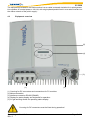
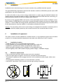
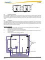
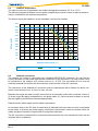

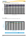
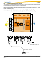
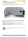
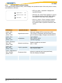
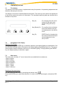
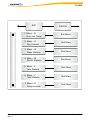

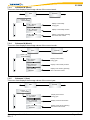
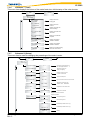
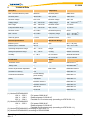
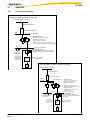
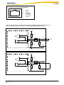
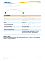


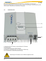
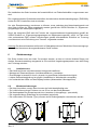
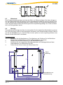
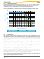
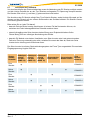
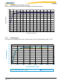
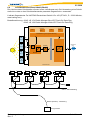
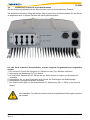
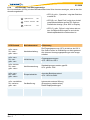
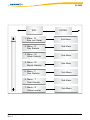
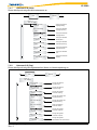
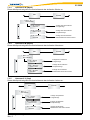
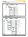
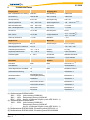
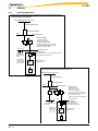
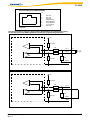


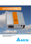


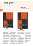
![Fronius Power Control Box [42,0426,0081,DE]](http://vs1.manualzilla.com/store/data/006752103_1-d5425e0b5bcbec528f5a1b8da9a30fb5-150x150.png)