1
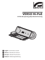
VERSO Hi-PoE
Hi-PoE side opening polycarbonate housing
EN English - Instructions manual
IT Italiano - Manuale di istruzioni
FR Français - Manuel d'instructions
DE Deutsch - Bedienungslanleitung
VERSO Hi-PoE
Hi-PoE side opening polycarbonate housing
EN English - Instructions manual
Contents
EN - English - Instructions manual
ENGLISH
1 About this manual......................................................................................................... 3
1.1 Typographical conventions................................................................................................................................. 3
2 Notes on copyright and information on trademarks................................................. 3
3 Safety rules.................................................................................................................... 3
4 Identification................................................................................................................. 4
4.1 Product description and type designation.................................................................................................... 4
4.2 Product markings.................................................................................................................................................... 4
5 Preparing the product for use...................................................................................... 4
5.1 Contents and unpacking...................................................................................................................................... 4
5.2 Safely disposing of packaging material.......................................................................................................... 4
6 Installing and assembling............................................................................................. 5
6.1 Installation................................................................................................................................................................. 5
6.1.1 How to open the housing.................................................................................................................................................... 5
6.1.2 How to install the camera.................................................................................................................................................... 5
6.1.2.1 RJ45 connection........................................................................................................................................................................................... 5
6.1.3 Cooling device......................................................................................................................................................................... 6
7 Maintaining and cleaning............................................................................................. 7
7.1 Window and plastic cover cleaning (PC)......................................................................................................... 7
8 Disposal of waste materials.......................................................................................... 7
9 Technical specifications................................................................................................ 7
9.1 General........................................................................................................................................................................ 7
9.2 Mechanical................................................................................................................................................................. 7
9.3 Electrical..................................................................................................................................................................... 7
9.4 Environment.............................................................................................................................................................. 7
9.5 Compliance to.......................................................................................................................................................... 8
10 Technical drawings...................................................................................................... 8
2
3 Safety rules
Before installing and using this unit, please read this
manual carefully. Be sure to keep it handy for later
reference.
hh
1.1 Typographical conventions
DANGER!
High level hazard.
Risk of electric shock. Disconnect the
power supply before proceeding with any
operation, unless indicated otherwise.
gg
WARNING!
Medium level hazard.
This operation is very important for the
system to function properly. Please read
the procedure described very carefully and
carry it out as instructed.
hh
INFO
Description of system specifications.
We recommend reading this part carefully
in order to understand the subsequent
stages.
jj
The manufacturer declines all responsibility
for any damage caused by an improper use
of the appliances mentioned in this manual.
Furthermore, the manufacturer reserves
the right to modify its contents without any
prior notice. The documentation contained
in this manual has been collected with great
care, the manufacturer, however, cannot
take any liability for its use. The same thing
can be said for any person or company
involved in the creation and production of
this manual.
• The device must be installed only and exclusively
by qualified technical personnel.
• Before any technical work on the appliance,
disconnect the power supply.
• Do not use power supply cables that seem worn
or old.
• Never, under any circumstances, make any
changes or connections that are not shown in
this handbook: improper use of the appliance
can cause serious hazards, risking the safety of
personnel and of the installation.
2 Notes on copyright and
information on trademarks
• Use only original spare parts. Not original spare
parts could cause fire, electrical discharge or other
hazards.
The quoted names of products or companies are
trademarks or registered trademarks.
• Before proceeding with installation check the
supplied material to make sure it corresponds
to the order specification by examining the
identification labels ("4.2 Product markings", page 4).
3
EN - English - Instructions manual
1 About this manual
EN - English - Instructions manual
4 Identification
4.1 Product description and type
designation
The VERSO Hi-PoE camera housing assures easy plug
and play mounting, system reliability, economical
service and installation for the IP and Megapixel
cameras, thanks to the benefits of High Power PoE
(Power over Ethernet). This technology allows to feed
the 12Vdc cameras as well as the heater directly from
the Ethernet cable. No need to add external power
sources or bring additional power cables into the
enclosure.
If your network does not have Hi-PoE, you can add
it by using the 1 channel Power Injector (accessory
available as an option), in addition Videotec certifies
the compatibility of the Microsemi/PowerDsine HiPoE
Multi Port 7000 Midspans series (available in 6,12 and
24 port versions).
The VERSO Hi-PoE housing ensures total protection
against all environmental conditions. Due to its
side opening, the accessibility to the camera, lens
and all its connections is made far easier. Entirely
manufactured from the newest, most resistant
technopolymer, VERSO Hi-PoE guarantees high
impact resistance, weather protection from external
agents and UV rays. Its weatherproof features are
ensured by the neoprene-rubber gaskets and the
3 cable glands or installed with an internal cable
management bracket and optional sealing rings.
VERSO Hi-PoE offers the possibility of various
mounting options: wall mounted bracket, cable
managed bracket, or on a Pan & Tilt head. A specific
version with a very efficient cooling system is
available for installations with high environmental
temperature.
4.2 Product markings
See the label attached to the outside of the package.
5 Preparing the product
for use
Any change that is not expressly approved
by the manufacturer will invalidate the
guarantee.
hh
5.1 Contents and unpacking
When the product is delivered, make sure that the
package is intact and that there are no signs that it
has been dropped or scratched.
If there are obvious signs of damage, contact the
supplier immediately.
Keep the packaging in case you need to send the
product for repairs.
Check the contents to make sure they correspond
with the list of materials as below:
• VERSO Hi-PoE housing
• RJ45 wiring
• Housing equipment:
• Allen wrench
• Spacers
• Cable glands
• Screws and washers
• Screws for camera
• Desiccant salt bag
• Instructions manual
5.2 Safely disposing of
packaging material
The packaging material can all be recycled. The
installer technician will be responsible for separating
the material for disposal, and in any case for
compliance with the legislation in force where the
device is to be used.
Bear in mind that if the material has to be returned
due to a fault, using the original packaging for its
transport is strongly recommended.
4
6 Installing and
assembling
The housing where this device is installed
must be powered by 12Vdc or 24Vac
voltage.
hh
03
01
02
Turn off the power before performing any
operations.
hh
6.1 Installation
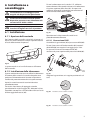
Fig. 02
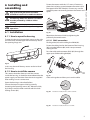
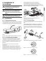
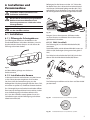
6.1.1 How to open the housing
Reposition the internal slide by tightening the
previously loosened screws.
To open the housing, loosen the 2 screws on the side,
turn the cover and the upper half of the body about
the opening hinge axis.
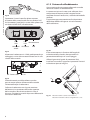
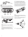
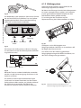
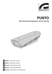
6.1.2.1 RJ45 connection
Fit the gasket (01) to the cable gland M20 (02).
Fasten the cable gland to the bottom of the housing
(03) using the M20 nut (04) with a torque wrench
setting of 7Nm.
Pass the cable with connector RJ45 (05) through the
upper part of M20 cable gland(06).
04
01
02
05
Fig. 01
06
In this way there will be easy access to the inside of
the housing.
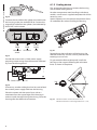
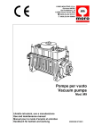
6.1.2 How to install the camera
This section describes how to install the camera
inside the housing. It should be remembered that the
power supply can be taken from the circuit supplied
after making sure it is correct one.
03
Fig. 03
Choose the gasket and then put it on the cable.
Open the housing as described before.
Extract the internal support slide by partially
loosening the fastening screws (01). Move the slide,
by sliding it until the holes coincide with the slide
locking screws (02).
Fig. 04
Diameter of cable; from 3..5mm a 5.5mm.
Fig. 05
Diameter of cable: from 5.5 to 7.5 mm.
5
EN - English - Instructions manual
Only specialised personnel should be
allowed to install and assemble the device.
hh
Fasten the camera with the 1/4" screw; if necessary
place the insulating spacer between the camera and
the upper half of the slide (03). If necessary, use the
supplied spacers to correctly position the camera and
optics.
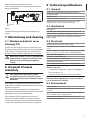
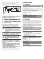
This section describes how to connect the housing
with installed cooling device.
No other components need installing inside these
models, as each one is supplied complete with all the
necessary parts.
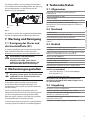
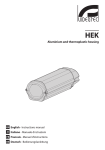
Fig. 06
Connect the net calbe to the splitter mounted inside
the housing in the slot marked POE IN. Connect the
output RJ45 cable from the splitter (slot indicated by
DATA OUT) to the camera.
POE IN
Special attention must be paid to the position of the
air intake filter fins when installing the housing.
IN
DATA OUT DC OUT
LAN
Cable
LAN
Cable
Power
supply
MIDSPAN
switch
IP Camera
PCB
Fig. 07
Provide the camera with a 12Vdc power supply,
preparing output wiring from the terminal indicated
by J4 on the housing board.
OUT
Fig. 09
Depending on the inclination of the housing, the
direction of the fins must be such to prevent water
entering in case of rain.
To guarantee the IP44 weatherproof, install the
housing on the support following the inclination
limits as shown in the picture.
45°
J4 - Camera OUT
J3 - IN
0˚
Fig. 08
45°
EN - English - Instructions manual
6.1.3 Cooling device
If necessary, another cable gland can be used to feed
the camera power supply cable into the housing.
Place the camera with the optics front side to a
centimeter from the upper edge of the housing in
order to avoid damages during the closing. Close the
housing after the electrical connections.
6
Fig. 10
Maximal rotation on the transversal axis: 0˚.
Maximal inclination on the longitudinal axis: +/- 45˚.
Open the housing as explained above.
In this circuit the camera can be powered from the
terminal marked J5.
9 Technical specifications
EN - English - Instructions manual
9.1 General
Entirely made of technopolymer (polycarbonate)
Sunshield in ABS
RAL9002 Colour
Stainless steel external screws
J5 - Camera
OUT
J1 - IN
Supplied with instruction manual, desiccants bag,
accessories for camera and lens mounting
9.2 Mechanical
Fig. 11
Cable glands
Close the housing following these instructions in
reverse.
Polycarbonate window (BxH): 105x64mm (4.1x2.5in)
7 Maintaining and cleaning
Internal usable length with and without accessories:
230mm (9.0in)
7.1 Window and plastic cover
cleaning (PC)
9.3 Electrical
Surface dirt should be rinsed away with water and
then the window cleaned with a neutral soap diluted
with water, or specific products for spectacle lens
cleaning. These should be applied with a soft cloth.
Avoid ethyl alcohol, solvents, hydrogenated
hydrocarbide, strong acid and alkali. Such
products may irreparably damage the
surface.
hh
8 Disposal of waste
materials
This symbol mark and recycle system
are applied only to EU countries and not
applied to the countries in the other area of
the world.
nn
Your product is designed and manufactured with
high quality materials and components which can be
recycled and reused.
This symbol means that electrical and electronic
equipment, at their end-of-life, should be disposed of
separately from your household waste.
Please dispose of this equipment at your local
Community waste collection or Recycling centre.
Internal usable area (BxH): 70x70mm (2.7x2.7in)
Available power for camera: 10W, 12Vdc
Heater Ton 15°C+/-3°C (59°F +/-5°F) Toff 22°C+/-3°C (71°F
+/-5°F)
Blower with thermostat Ton 35°C+/-3°C (95°F+/-5°F) Toff
20°C+/-3°C (71°F+/-5°F) for version with double filter
PoE IN: 10/100/1000Base-T
Data OUT: 10/100/1000Base-T
DC OUT: 12Vdc, external pole GND
Input Voltage: 44-57Vdc
Input Current: 570mA max @Vin = 42Vdc, full-load
Compatible with the Power Injector (ref. OHEPOWINJ
Videotec accessory)
-- 1 channel PoE supply PoE - LAN 10/100/1000Base-T
-- IN AC 90/264Vac, 1A
-- Operating temperature: 0°C/+40°C (32°F/104°F)
Compatible also with the Microsemi/PowerDsine
HiPoE Multi Port 7000 Midspans series (available in
6,12 and 24 channels versions)
9.4 Environment
Indoor / Outdoor
Operating temperature with heater: -20°C / +50°C (-4°F
/ +122°F)
Very good resistance to the following chemical agents:
basics, alcohols, gasses, hydrocarbon
Good resistance: organic and inorganic acids, oils
Low resistance: solvents
In the European Union there are separate collection
systems for used electrical and electronic products.
7
9.5 Compliance to
cable channel
IP44 according to EN 60529 with double filter housing
CE according to EN61000-6-3, EN 60950, EN50130-4
V1 fire-self extinguish compliance according to UL94
IP66 according to EN 60529 with cable glands
Impact resistance IK10 according to EN 50102
IP66 according to EN 60529 with special gasket and
bracket with internal cable channel
IP54 according to EN 60529 with bracket with internal
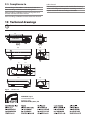
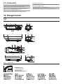
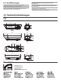
10 Technical drawings
The values are in millimeters.
230
70
USABLE AREA
USABLE
AREA
A A
B B
466
156
113
A
B
141
B
70
jj
A
70
171
73
70
62
70
40
101
156
Fig. 12
VERSO Hi-PoE
VIDEOTEC S.p.A.
www.videotec.com
Printed in Italy
MNVCHPVPOE_0943_EN
129
422
VERSO Hi-PoE
Custodia Hi-PoE in policarbonato ad apertura laterale
IT Italiano - Manuale di istruzioni
Sommario
ITALIANO
1 Informazioni sul presente manuale............................................................................. 3
IT - Italiano - Manuale di istruzioni
1.1 Convenzioni tipografiche..................................................................................................................................... 3
2 Note sul copyright e informazioni sui marchi commerciali....................................... 3
3 Norme di sicurezza........................................................................................................ 3
4 Identificazione............................................................................................................... 4
4.1 Descrizione e designazione del prodotto...................................................................................................... 4
4.2 Marcatura del prodotto......................................................................................................................................... 4
5 Preparazione del prodotto per l'utilizzo..................................................................... 4
5.1 Contenuto e disimballaggio................................................................................................................................ 4
5.2 Smaltimento in sicurezza dei materiali di imballaggio.............................................................................. 4
6 Installazione e assemblaggio....................................................................................... 5
6.1 Installazione.............................................................................................................................................................. 5
6.1.1 Apertura della custodia........................................................................................................................................................ 5
6.1.2 Installazione della telecamera............................................................................................................................................ 5
6.1.2.1 Connessione RJ45........................................................................................................................................................................................ 5
6.1.3 Sistema di raffreddamento.................................................................................................................................................. 6
7 Manutenzione e pulizia................................................................................................ 7
7.1 Pulizia del vetro e delle parti in plastica (PC)................................................................................................. 7
8 Smaltimento dei rifiuti.................................................................................................. 7
9 Dati tecnici..................................................................................................................... 7
9.1 Generale..................................................................................................................................................................... 7
9.2 Meccanica.................................................................................................................................................................. 7
9.3 Elettrico....................................................................................................................................................................... 7
9.4 Ambiente.................................................................................................................................................................... 7
9.5 Conformità................................................................................................................................................................. 8
10 Disegni tecnici............................................................................................................. 8
2
1 Informazioni sul presente
manuale
1.1 Convenzioni tipografiche
PERICOLO!
Pericolosità elevata.
Rischio di scosse elettriche. Togliere
l'alimentazione prima di procedere con le
operazioni, salvo diversa indicazione.
gg
ATTENZIONE!
Pericolosità media.
L'operazione è molto importante per il
corretto funzionamento del sistema. Si
prega di leggere attentamente la procedura
indicata e di eseguirla secondo le modalità
previste.
hh
INFO
Descrizione delle caratteristiche del
sistema.
Si consiglia di leggere attentamente per
comprendere le fasi successive.
jj
2 Note sul copyright e
informazioni sui marchi
commerciali
I nomi di prodotto o di aziende citati sono marchi
commerciali o marchi commerciali registrati
appartenenti alle rispettive società.
Il produttore declina ogni responsabilità
per eventuali danni derivanti da un
uso improprio delle apparecchiature
menzionate in questo manuale. Si
riserva inoltre il diritto di modificarne il
contenuto senza preavviso. Ogni cura è
stata posta nella raccolta e nella verifica
della documentazione contenuta in questo
manuale, tuttavia il produttore non può
assumersi alcuna responsabilità derivante
dall'utilizzo della stessa. Lo stesso dicasi
per ogni persona o società coinvolta nella
creazione e nella produzione di questo
manuale.
hh
• L'installazione e la manutenzione del dispositivo
deve essere eseguita solo da personale tecnico
qualificato.
• Prima di effettuare interventi tecnici
sull'apparecchio togliere l'alimentazione elettrica.
• Non utilizzare cavi di alimentazione con segni di
usura o invecchiamento.
• Non effettuare per nessun motivo alterazioni o
collegamenti non previsti in questo manuale:
l'uso di apparecchi non idonei può portare a
gravi pericoli per la sicurezza del personale e
dell'impianto.
• Utilizzare solo parti di ricambio originali. Pezzi di
ricambio non originali potrebbero causare incendi,
scariche elettriche o altri pericoli.
• Prima di procedere con l'installazione controllare
che il materiale fornito corrisponda alle specifiche
richieste esaminando le etichette di marcatura ("4.2
Marcatura del prodotto", pagina 4).
3
IT - Italiano - Manuale di istruzioni
Prima di installare e utilizzare questa unità, leggere
attentamente questo manuale. Conservare questo
manuale a portata di mano come riferimento futuro.
3 Norme di sicurezza
4 Identificazione
IT - Italiano - Manuale di istruzioni
4.1 Descrizione e designazione
del prodotto
L’innovativa custodia VERSO Hi-PoE assicura estrema
semplicità di montaggio, affidabilità e risparmio
per l’installazione delle telecamere IP e Megapixel
grazie ai vantaggi dello standard High Power PoE
(Power over Ethernet). Questa tecnologia rende
possibile l’alimentazione della telecamera 12Vdc
e del riscaldamento direttamente dal cavo di rete
Ethernet standard. Non serve portare altri cavi di
alimentazione all’interno della custodia.
Se l’HiPoE non è fornito direttamente dalla rete,
la custodia può essere alimentata tramite il Power
Injector a 1 canale (accessorio disponibile su
richiesta). Videotec garantisce inoltre la piena
compatibilità del sistema con il Midspan serie
Microsemi/PowerDsine HiPoE Multi Port 7000
disponibile a 6, 12 o 24 porte.
VERSO Hi-PoE assicura una protezione totale a
tutte le condizioni ambientali, mentre l’apertura
laterale facilita ampiamente l’accessibilità alla
telecamera. Costruita interamente in resistente
tecnopolimero, VERSO Hi-PoE assicura un’elevata
resistenza agli impatti, un’alta protezione contro
gli agenti atmosferici ed ai raggi UV. La tenuta
stagna è mantenuta dalle guarnizioni in gomma
neoprene e da 3 pressacavi o dagli anelli di
tenuta accessori, se installata con supporto per
passaggio interno dei cavi. VERSO Hi-PoE offre
diverse varianti di montaggio, supporto a parete,
supporto con passaggio interno cavi e brandeggio
È disponibile una versione con un sistema di
ventilazione altamente efficiente per applicazioni con
temperature elevate.
4.2 Marcatura del prodotto
Vedere l’etichetta posta sull’esterno dell’imballo.
5 Preparazione del
prodotto per l'utilizzo
Qualsiasi cambiamento non espressamente
approvato dal costruttore fa decadere la
garanzia.
hh
5.1 Contenuto e disimballaggio
Alla consegna del prodotto verificare che l'imballo
sia integro e non abbia segni evidenti di cadute o
abrasioni.
In caso di evidenti segni di danno all'imballo
contattare immediatamente il fornitore.
Conservare l'imballo nel caso sia necessario inviare il
prodotto in riparazione.
Controllare che il contenuto sia rispondente alla lista
del materiale sotto indicata:
• Custodia VERSO Hi-PoE
• Cablaggio RJ45
• Dotazione per custodia:
• Chiave a brugola
• Distanziali
• Pressacavi
• Viti e rondelle
• Viti per telecamera
• Sacchetto sali essiccanti
• Manuale di istruzioni
5.2 Smaltimento in sicurezza
dei materiali di imballaggio
I materiali d'imballo sono costituiti interamente da
materiale riciclabile. Sarà cura del tecnico installatore
smaltirli secondo le modalità di raccolta differenziata
o comunque secondo le norme vigenti nel Paese di
utilizzo.
Si ricorda comunque che in caso di ritorno di
materiale con malfunzionamenti è consigliato
l'imballaggio originale per il trasporto.
4
6 Installazione e
assemblaggio
L'installazione e l'assemblaggio vanno
eseguiti solo da personale specializzato.
hh
IT - Italiano - Manuale di istruzioni
Le versioni di custodia munite di questo
dispositivo possono essere alimentate solo
con tensioni di 12Vdc o 24Vac.
hh
Fissare la telecamera con la vite da 1/4"; collocare
eventualmente il distanziale isolante tra la telecamera
e la parte superiore della slitta (03). Se necessario
utilizzare i distanziali in dotazione per collocare nel
modo corretto telecamera e ottica.
03
01
02
Prima di eseguire qualsiasi operazione
ricordarsi di togliere tensione al prodotto.
hh
6.1 Installazione
Fig. 02
6.1.1 Apertura della custodia
Riposizionare la slitta interna fissando le viti
precedentemente allentate.
Per l’apertura della custodia, svitare le 2 viti poste sul
fianco, far ruotare tettuccio e corpo superiore attorno
all’asse delle cerniere di apertura.
6.1.2.1 Connessione RJ45
Assemblare la guarnizione (01)al pressacavo M20 (02).
Fissare il pressacavo al fondo custodia (03) tramite il
dado M20 (04) con coppia di serraggio pari a 7Nm.
Far passare il cavo con connettore RJ45 (05)
attraverso la parte superiore del pressacavo M20 (06).
04
01
02
05
06
Fig. 01
In questo modo vi sarà un facile accesso all’interno
della custodia.
6.1.2 Installazione della telecamera
Questa sezione descrive come installare la telecamera
all’interno della custodia. Si ricorda che può essere
prelevata l’alimentazione dal circuito in dotazione
verificando preventivamente che sia quella corretta.
03
Fig. 03
Scegliere la guarnizione. e in seguito posizionarla sul
cavo.
Aprire la custodia come da istruzioni descritte
precedentemente.
Estrarre la slitta interna di appoggio svitando
parzialmente le viti di fissaggio (01). Muovere la slitta
facendola scorrere fino a far coincidere i fori con le viti
di bloccaggio della stessa (02).
Fig. 04
Diametro cavo da 3.5mm a 5.5mm.
Fig. 05
Diametro cavo da 5.5mm a 7.5mm.
5
6.1.3 Sistema di raffreddamento
Fig. 06
Connettere il cavo di rete allo splitter montato
all’interno della custodia nello slot con dicitura POE
IN. Connettere il cavo RJ45 in uscita dallo splitter (slot
con dicitura DATA OUT) alla telecamera.
POE IN
In queste versioni non è necessario collocare alcun
componente all’interno perché vengono fornite
complete di tutto il necessario, a seconda del modello
richiesto.
È importante prestare attenzione alla disposizione
delle alette del filtro d’ingresso aria nel momento
dell’installazione.
DATA OUT DC OUT
IN
Cavo
LAN
MIDSPAN
switch
Cavo Alimentazione
LAN
IP Camera
PCB
Fig. 09
Fig. 07
Alimentare la telecamera in 12Vdc predisponendo un
cablaggio in uscita dal morsetto indicato con J4 sulla
scheda della custodia.
Il loro orientamento, in funzione dell’angolo di
inclinazione della custodia, deve prevenire la
penetrazione dell’acqua in caso di pioggia.
Al fine di garantire il grado di protezione IP44,
installare la custodia al supporto rispettando i limiti di
inclinazione riportati in figura.
J3 - IN
Fig. 08
45°
J4 - Camera OUT
OUT
0˚
Eventualmente è possibile utilizzare un altro
pressacavo per portare all’interno della custodia
l’alimentazione per la telecamera.
Collocare la telecamera con la parte anteriore
dell’ottica ad un centimetro dal bordo superiore
della custodia al fine di evitare danni in fase di
chiusura. Chiudere la custodia dopo aver effettuato le
connessioni elettriche.
6
45°
IT - Italiano - Manuale di istruzioni
Questa sezione descrive come collegare le custodie
munite di sistema di raffreddamento.
Fig. 10
Massima rotazione sull'asse trasversale: 0˚.
Massima inclinazione sull'asse longitudinale: +/- 45˚.
Aprire la custodia come da istruzioni precedenti.
Nel circuito c’è la possibilità di prelevare
l’alimentazione per una telecamera sul morsetto
indicato con J5.
9 Dati tecnici
9.1 Generale
Costruita in resistente tecnopolimero (policarbonato)
Tettuccio in ABS
IT - Italiano - Manuale di istruzioni
Colore RAL9002
Viteria esterna in acciaio Inox
Fornita con manuale di istruzioni, sacchetto sale,
accessori montaggio telecamera e obiettivo
J5 - Camera
OUT
J1 - IN
Fig. 11
9.2 Meccanica
3 pressacavi
Finestra policarbonato (BxH): 105x64mm
Chiudere la custodia operando in maniera inversa a
quanto descritto precedentemente.
Dimensioni utili interne (BxH): 70x70mm
7 Manutenzione e pulizia
9.3 Elettrico
7.1 Pulizia del vetro e delle parti
in plastica (PC)
Potenza disponibile per telecamera: 10W, 12Vdc
Si consigliano saponi neutri diluiti con acqua o
prodotti specifici per la pulizia delle lenti degli
occhiali con l’utilizzo di un panno morbido.
Sono da evitare alcool etilico, solventi,
idrocarburi idrogenati, acidi forti e alcali.
L’utilizzo di detti prodotti danneggia in
modo irreparabile la superficie delle parti
in plastica.
hh
8 Smaltimento dei rifiuti
Questo simbolo e il sistema di riciclaggio
sono validi solo nei paesi dell'EU e non
trovano applicazione in altri paesi del
mondo.
nn
Il vostro prodotto è stato costruito da materiali e
componenti di alta qualità, che sono riutilizzabili o
riciclabili.
Prodotti elettrici ed elettronici che portano questo
simbolo alla fine dell'uso devono essere smaltiti
separatamente dai rifiuti casalinghi.
Vi preghiamo di smaltire questo apparecchio in un
Centro di raccolta o in un'Ecostazione.
Lunghezza utile interna con e senza accessori: 230mm
Riscaldamento Ton 15°C+/-3°C Toff 22°C+/-3°C
Ventilatore con termostato Ton 35°C+/-3°C Toff 20°C+/3°C per modelli con doppio filtro per ricambio aria
PoE IN: 10/100/1000Base-T
Data OUT: 10/100/1000Base-T
DC OUT: 12Vdc, polo esterno GND
Voltaggio d’ingresso: 44-57Vdc
Corrente d’ingresso: 570mA max @Vin = 42Vdc, pieno
carico
Compatibile con Power Injector (accessorio opzionale
Videotec ref. OHEPOWINJ)
-- 1 canale alimentazione PoE - LAN 10/100/1000Base-T
-- IN AC 90/264Vac, 1
-- Temperatura d’esercizio: 0°C/ +40°C
Compatibile anche con Midspan serie Microsemi/
PowerDsine HiPoE Multi Port 7000 disponibile a 6, 12
o 24 porte
9.4 Ambiente
Interno / Esterno
Temperatura d’esercizio con riscaldamento: -20°C / +50°C
Resistenza molto buona ai seguenti agenti chimici: basi,
alcoli, gas, idrocarburi
Resistenza buona: acidi organici e inorganici, olii
Resistenza bassa: solventi
Nell'Unione Europea esistono sistemi di raccolta
differenziata per prodotti elettrici ed elettronici.
7
9.5 Conformità
passaggio interno cavi
CE in accordo con EN61000-6-3, EN 60950, EN50130-4
IP44 in accordo con EN 60529 per modelli con doppio
filtro per ricambio d’aria
IP66 in accordo con EN 60529 con pressacavi
Autoestinguente V1 secondo UL94
IP66 in accordo con EN 60529 con anelli di tenuta e
supporto con passaggio interno cavi
Resistenza agli impatti IK10 secondo EN 50102
IP54 in accordo con EN 60529 con supporto con
10 Disegni tecnici
I valori espressi sono in millimetri.
230
70
AREA UTILE
AREA
UTILE
A A
B B
466
156
113
A
B
141
B
70
jj
A
70
171
73
70
62
70
40
101
156
Fig. 12
VERSO Hi-PoE
VIDEOTEC S.p.A.
www.videotec.com
Printed in Italy
MNVCHPVPOE_0943_IT
129
422
VERSO Hi-PoE
Caisson Hi-PoE en poly carbonate à ouverture latérale
FR Français - Manuel d'instructions
Sommaire
FRANÇAIS
1 À propos de ce mode d’emploi..................................................................................... 3
FR - Français - Manuel d'instructions
1.1 Conventions typographiques............................................................................................................................. 3
2 Notes sur le copyright et informations sur les marques de commerce..................... 3
3 Normes de securité........................................................................................................ 3
4 Identification................................................................................................................. 4
4.1 Description et désignation du produit............................................................................................................ 4
4.2 Marquage du produit............................................................................................................................................ 4
5 Préparation du produit en vue de l’utilisation............................................................ 4
5.1 Contenu et déballage............................................................................................................................................ 4
5.2 Élimination sans danger des matériaux d’emballage................................................................................ 4
6 Installation et assemblage............................................................................................ 5
6.1 Installation................................................................................................................................................................. 5
6.1.1 Ouverture du caisson............................................................................................................................................................. 5
6.1.2 Installation de la caméra...................................................................................................................................................... 5
6.1.2.1 Connexion RJ45............................................................................................................................................................................................ 5
6.1.3 Système de refroidissement................................................................................................................................................ 6
7 Entretien et nettoyage.................................................................................................. 7
7.1 Entretiens de la vitre et des parties en plastique (PC)................................................................................ 7
8 Élimination des déchets................................................................................................ 7
9 Données techniques...................................................................................................... 7
9.1 Généralités................................................................................................................................................................. 7
9.2 Mécanique................................................................................................................................................................. 7
9.3 Électrique................................................................................................................................................................... 7
9.4 Environnement........................................................................................................................................................ 7
9.5 En conformité avec................................................................................................................................................. 8
10 Dessins techniques...................................................................................................... 8
2
1 À propos de ce mode
d’emploi
Avant d’installer et d’utiliser cet appareil, veuillez
lire attentivement ce mode d’emploi. Conservez-le à
portée de main pour pouvoir vous y reporter en cas
de besoin.
DANGER!
Risque élevé.
Risque de choc électrique. Sauf indication
contraire, sectionner l’alimentation avant
de procéder à toute opération.
gg
ATTENTION!
Risque moyen.
Opération extrêmement importante en vue
d’un fonctionnement correct du système;
lire avec attention les opérations indiquées
et s’y conformer rigoureusement.
hh
REMARQUE
Description des caractéristiques du
système.
Il est conseillé de procéder à une
lecture attentive pour une meilleure
compréhension des phases suivantes.
jj
2 Notes sur le copyright
et informations sur les
marques de commerce
Les noms de produit ou de sociétés cités sont des
marques de commerce ou des marques de commerce
enregistrées.
Le producteur décline toute responsabilité
pour les dommages éventuels dus à une
utilisation non appropriée des appareils
mentionnés dans ce manuel. On réserve
en outre le droit d’en modifier le contenu
sans préavis. La documentation contenue
dans ce manuel a été rassemblée et vérifiée
avec le plus grand soin, cependant, le
producteur ne peut pas s’assumer aucune
responsabilité dérivante de l’emploi de
celle là. La même chose vaut pour chaque
personne ou société impliquées dans la
création et la production de ce manuel.
hh
• L’installation et l’entretien du dispositif doivent
être exclusivement être effectués par un personnel
technique qualifié.
• Sectionner l’alimentation électrique avant toute
intervention technique sur l’appareil.
• Ne pas utiliser de câbles d’alimentation usés ou
endommagés.
• Ne procéder sous aucun prétexte à des
modifications ou des connexions non prévues
dans ce manuel: l’utilisation d’appareils non
adéquats peut comporter des dangers graves pour
la sécurité du personnel et de l’installation.
• Utiliser uniquement des pièces de rechange
d’origine. Les pièces non d’origine peuvent être
source d’incendies, de choc électrique ou autres.
• Avant de procéder à l’installation, contrôler que
le matériel fourni correspond à la commande
et examiner les étiquettes de marquage ("4.2
Marquage du produit", page 4).
3
FR - Français - Manuel d'instructions
1.1 Conventions typographiques
3 Normes de securité
4 Identification
FR - Français - Manuel d'instructions
4.1 Description et désignation
du produit
Videotec lance le caisson VERSO Hi-PoE et assure une
extrême facilité, fiabilité et économie d’installation
des caméras réseau et Megapixel grâce aux avantages
offerts par le standard High Power PoE (Power over
Ethernet). Cette technologie permet l’alimentation
directe des caméras 12Vdc et du chauffage par câble
de réseau Ethernet standard. Aucun autre câble
d’alimentation supplementaire doit être acheminé à
l’intérieur du caisson.
Si le Hi-PoE n’est fourni directement du reseau, le
caisson peut être alimenté par le power injector à 1
canal (accessoire disponible sur demande). Videotec
garantit en plus une complète compatibilité du
système avec le Midspan de la série Microsemi/
PowerDsine HiPoE Multi Port 7000 disponible à 6, 12
ou 24 portes.
Caisson moderne et novateur, étudié pour simplifier
l’installation et la maintenance, VERSO Hi-PoE assure
une protection maximum dans les environnements
les plus difficiles. Son ouverture latérale facilite
l’accès et la mise en place de la caméra. VERSO
Hi-PoE est entièrement fabriqué avec un nouveau
polycarbonate garantissant ainsi, une grande
résistance aux impacts, une excellente protection aux
agressions atmosphériques et aux rayons UV. Son
étanchéité est assurée grâce à des joints en néoprène,
et à 3 presse-étoupes ou par des passe-câbles
optionnels lors de l’utilisation de supports creux,
permettant le passage protégé des câbles.
VERSO Hi-PoE permet d’utiliser différents modes
de fixation: support standard, support creux ou
installé sur une tourelle. Une version avec ventilateur
rend possible le bon fonctionnement lorsque la
température extérieure est élévée.
4.2 Marquage du produit
Voir l’étiquette sur l’extérieur de l’emballage.
4
5 Préparation du produit
en vue de l’utilisation
Toute modification non approuvée
expressément par le fabricant entraînera
l’annulation de la garantie.
hh
5.1 Contenu et déballage
Lors de la livraison du produit, vérifier que
l’emballage est en bon état et l’absence de tout signe
évident de chute ou d’abrasion.
En cas de dommages évidents, contacter
immédiatement le fournisseur.
Conserver l’emballage en cas de nécessité
d’expédition du produit pour réparation.
Contrôler que le contenu correspond à la liste
matériel indiquée ci-dessous:
• Caisson VERSO Hi-PoE
• Câblage RJ45
• Dotation pour caisson:
• Clé Allen
• Entretoises
• Presse-étoupes
• Vis et rondelles
• Vis pour caméra
• Sachet sel déshydratant
• Manuel d'instructions
5.2 Élimination sans danger des
matériaux d’emballage
Le matériel d’emballage est entièrement composé
de matériaux recyclables. Le technicien chargé de
l’installation est tenu de l’éliminer conformément aux
dispositions en matière de collecte sélective et selon
les normes en vigueur dans le pays d’utilisation.
En cas de dysfonctionnement et de retour de
matériel, il est conseillé d’utiliser l’emballage original
pour le transport.
6 Installation et
assemblage
L’installation et l’assemblage doivent
exclusivement être effectués par un
personnel spécialisé.
hh
hh
Avant d’effectuer toute opération, il est
indispensable de couper l'alimentation.
03
01
02
hh
Fig. 02
6.1 Installation
Replacer la glissière interne en fixant les vis
précédemment desserrées.
6.1.1 Ouverture du caisson
6.1.2.1 Connexion RJ45
Pour l’ouverture du caisson, dévisser les 2 vis placées
sur le côté, faire tourner le toit pare-soleil et le corps
supérieur autour de l’axe des charnières d’ouverture.
Assembler la garniture (f01) au presse-étoupe M20
(02).
FR - Français - Manuel d'instructions
Les versions de caisson équipées de ce
dispositif peuvent exclusivement être
alimentées avec des tensions de 12Vdc ou
24Vac.
Fixer la caméra avec la vis de 1/4"; placer
éventuellement l’entretoise isolante entre la
caméra et la partie supérieure de la glissière (03). Si
nécessaire, utiliser les entretoises fournies pour placer
de façon correcte la caméra et l’optique.
Fixer le presse-étoupe au fond du caisson (03) via
l'écrou M20 (04) avec un couple de serrage de 7Nm.
Faire passer le câble avec connecteur RJ45 (05) à
travers la partie supérieure du presse-étoupe M20
(06).
04
01
02
05
06
Fig. 01
On aura ainsi un accès facile à l’intérieur du caisson.
6.1.2 Installation de la caméra
Cette section décrit comment installer la caméra
à l’intérieur du caisson. Nous rappelons qu’il est
possible de prélever l’alimentation à partir du circuit
fourni, en vérifiant, au préalable, que celle-ci soit
correcte.
03
Fig. 03
Sélectionner la garniture et l'installer sur le câble.
Ouvrez le caisson en suivant les instructions
précédentes.
Extraire la glissière interne d’appui en dévissant
partiellement les vis de fixation (01). Déplacer la
glissière en la faisant glisser jusqu’à ce que les trous
coincident avec les vis de blocage de celle-ci (02).
Fig. 04
Diamètre câble de 3.5mm à 5.5mm.
Fig. 05
Diamètre câble de 5.5mm à 7.5mm.
5
6.1.3 Système de refroidissement
Cette section décrit le mode de connexion des
caissons équipés d’un système de refroidissement.
Pour ces versions, aucun composant ne doit être
installé à l’intérieur, ces dernières étant fournies avec
tout le nécessaire en fonction du modèle requis.
Connecter le câble réseau au splitter monté à
l'intérieur du caisson dans le logement indiquant
POE IN. Connecter le câble RJ45 en sortie du splitter
(encoche indiquant DATA OUT) à la caméra.
POE IN
Cable
LAN
MIDSPAN
switch
Il est important contrôler la disposition des ailettes
du filtre d’entrée d’air lors de l’installation.
IN
DATA OUT DC OUT
Cable Alimentation
LAN
IP Camera
PCB
Fig. 07
Alimenter la caméra à 12Vdc en prévoyant un câblage
en sortie de la borne indiquée comme J4 sur la carte
du caisson.
OUT
Fig. 09
L’orientation des ailettes en fonction de l’angle
d’inclinaison du caisson doit empêcher toute entrée
d’eau en cas de pluie.
Pour garantir un degré de protection IP44, installer
le caisson au support en respectant les limites
d'inclinaison selon la figure.
45°
J4 - Camera OUT
J3 - IN
0˚
Fig. 08
45°
FR - Français - Manuel d'instructions
Fig. 06
Il est possible d’utiliser un autre presse-câble pour
amener l’alimentation de la caméra à l’intérieur du
caisson.
Placer la camèra avec la partie entérieure de l’optique
à un centimètre du bord supérieur du caisson
pour éviter des dommages pendant la fermeture.
Fermer le caisson après avoir effectué les connexion
électriques.
6
Fig. 10
Rotation maxi sur l’axe transversal: 0˚.
Inclination maxi sul l’axe longitudinal: +/- 45˚.
Ouvrir le caisson comme indiqué dans les instructions
précédentes.
9 Données techniques
Le circuit offre la possibilité de prélever l’alimentation
pour une caméra sur la borne indiquée comme J5.
9.1 Généralités
Construction en technopolymère de haute résistance
(poly carbonate)
Toit pare-soleil en ABS
Couleur RAL9002
J5 - Camera
OUT
J1 - IN
Fig. 11
Fermer le caisson en procédant selon les indications
précédentes mais en sens contraire.
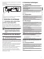
7 Entretien et nettoyage
7.1 Entretiens de la vitre et des
parties en plastique (PC)
Nous conseillons l’emploi, avec un chiffon souple,
de savons neutres dilués avec de l’eau ou bien de
produits spécifiques pour le nettoyage des verres de
lunettes.
On doit éviter: alcool éthylique, solvants,
hydrocarbures hydro-génés, acides forts
et alcali. L’emploi de ce type de produits
abîme d’une façon irréparable la surface
traitée.
hh
8 Élimination des déchets
Ce symbole et le système de recyclage ne
sont appliqués que dans les pays UE et non
dans les autres pays du monde.
nn
Votre produit est conçu et fabriqué avec des matèriels
et des composants de qualité supérieure qui peuvent
être recyclés et réutilisés.
Ce symbole signifie que les équipements électriques
et électroniques en fin de vie doivent être éliminés
séparément des ordures ménagères.
Nous vous prions donc de confier cet équipement à
votre Centre local de collecte ou Recyclage.
Dans l’Union Européenne, il existe des systèmes
sélectifs de collecte pour les produits électriques et
électroniques usagés.
FR - Français - Manuel d'instructions
Visserie extérieure en acier Inox
Livré avec manuel d’instructions, sachet déshydratant,
accessoires destinés au montage de la caméra et de
l’objectif
9.2 Mécanique
3 presse-étoupes
Fenêtre en poly carbonate (BxH): 105x64mm
Surface intérieure utile (BxH): 70x70mm
Longueur utile du caisson avec accessoires: 230mm
9.3 Électrique
Puissance disponible pour caméra: 10W, 12Vdc
Chauffage Ton 15°C+/-3°C Toff 22°C+/-3°C
Ventilateur avec thermostat Ton 35°C+/-3°C Toff
20°C+/-3°C pour les modèles avec double filtre pour le
renouvellement de l’air
PoE IN: 10/100/1000Base-T
Data OUT: 10/100/1000Base-T
DC OUT: 12Vdc, pôle externel GND
Tension d’entrée: 44-57Vdc
Courant d’entrée : 570mA max @Vin = 42Vdc, pleine
charge
Compatible avec le Power Injector à PoE (accessoire
Videotec en option réf. OHEPOWINJ)
-- 1 canal alimentation PoE - LAN 10/100/1000Base-T
-- IN AC 90/264Vac, 1
-- Température d’exercice : 0°C/+40°C
Compatible aussi avec le Midspan modél Microsemi/
PowerDsine HiPoE Multi Port 7000 disponible à 6, 12
ou 24 can.
9.4 Environnement
Intérieur / Extérieur
Température d’exercice avec chauffage: -20°C / +50°C
Très bonne résistance aux agents chimiques suivants:
bases, alcools, gaz, hydrocarbures
Bonne résistance: acides organiques et inorganiques,
huiles
Basse résistance: solvants
7
9.5 En conformité avec
des câbles
CE selon EN61000-6-3, EN 60950, EN50130-4
IP44 selon EN 60529 pour les modèles avec ventilateur
et double filtre
IP66 selon EN 60529 avec presse-étoupes
Auto-extinction V1 selon UL94
IP66 selon EN 60529 avec bagues d’étanchéité et
support avec passage interne des câbles
Résistance aux impacts IK10 selon EN 50102
IP54 selon EN 60529 avec support avec passage interne
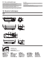
10 Dessins techniques
Les valeurs sont entendues en millimètres.
230
70
SURFACE UTILE
SURFACE
UTILE
A A
B B
466
156
113
A
B
141
B
70
jj
A
70
171
73
70
62
70
40
101
156
Fig. 12
VERSO Hi-PoE
VIDEOTEC S.p.A.
www.videotec.com
Printed in Italy
MNVCHPVPOE_0943_FR
129
422
VERSO Hi-PoE
Hi-PoE Polykarbonatgehäuse mit Seitenöffnung
DE Deutsch - Bedienungslanleitung
Inhaltsverzeichnis
DEUTSCH
1 Allgemeines................................................................................................................... 3
1.1 Schreibweisen.......................................................................................................................................................... 3
DE - Deutsch - Bedienungslanleitung
2 Anmerkungen zum Copyright und Informationen zu den Handelsmarken............. 3
3 Sicherheitsnormen........................................................................................................ 3
4 Identifizierung............................................................................................................... 4
4.1 Beschreibung und Bezeichnung des Produktes.......................................................................................... 4
4.2 Kennzeichnung des Produkts............................................................................................................................. 4
5 Vorbereitung des Produktes auf den Gebrauch......................................................... 4
5.1 Inhalt und Entfernen der Verpackung............................................................................................................. 4
5.2 Sichere Entsorgung der Verpackungsmaterialien....................................................................................... 4
6 Installation und Zusammenbau................................................................................... 5
6.1 Installation................................................................................................................................................................. 5
6.1.1 Öffnung des Schutzgehäuses............................................................................................................................................. 5
6.1.2 Installation der Kamera......................................................................................................................................................... 5
6.1.2.1 RJ45- Anschluß.............................................................................................................................................................................................. 5
6.1.3 Kühlungsystem........................................................................................................................................................................ 6
7 Wartung und Reinigung................................................................................................ 7
7.1 Reinigung des Glases und der Kunststoffteile (PC)..................................................................................... 7
8 Müllentsorgungsstellen................................................................................................ 7
9 Technische Daten........................................................................................................... 7
9.1 Allgemeines............................................................................................................................................................... 7
9.2 Mechanik.................................................................................................................................................................... 7
9.3 Elektrik......................................................................................................................................................................... 7
9.4 Umgebung................................................................................................................................................................ 7
9.5 Zertifizierungen....................................................................................................................................................... 8
10 Technische Zeichnungen............................................................................................ 8
2
1 Allgemeines
3 Sicherheitsnormen
Lesen Sie bitte vor dem Installieren und dem
Verwenden dieses Gerätes die Bedienungsanleitung
sorgfältig durch. Bewahren Sie sie zum späteren
Nachschlagen auf.
hh
1.1 Schreibweisen
ACHTUNG!
Mittlere Gefährdung.
Der genannte Vorgang hat große
Bedeutung für den einwandfreien Betrieb
des Systems: es wird gebeten, sich die
Verfahrensweise anzulesen und zu
befolgen.
hh
ANMERKUNG
Beschreibung der Systemmerkmale.
Eine sorgfältige Lektüre wird empfohlen,
um das Verständnis der folgenden Phasen
zu gewährleisten.
jj
2 Anmerkungen
zum Copyright und
Informationen zu den
Handelsmarken
• Die Installation und Wartung der Vorrichtung ist
technischen Fachleuten vorbehalten.
• Vor technischen Eingriffen am Gerät muss die
Stromversorgung unterbrochen werden.
• Es dürfen keine Versorgungskabel mit Verschleißoder Alterungsspuren verwendet werden.
• Unter keinen Umständen dürfen Veränderungen
oder Anschlüsse vorgenommen werden, die
in diesem Handbuch nicht genannt sind: Der
Gebrauch ungeeigneten Geräts kann die Sicherheit
des Personals und der Anlage schwer gefährden.
• Es dürfen nur Original-Ersatzteile verwendet
werden. Nicht originale Ersatzteile können zu
Bränden, elektrischen Entladungen oder anderen
Gefahren führen.
• Vor der Installation ist anhand des
Kennzeichnungsschildes nachzuprüfen, ob das
gelieferte Material die gewünschten Eigenschaften
aufweist ("4.2 Kennzeichnung des Produkts", Seite 4).
Die angeführten Produkt- oder Firmennamen sind
Handelsmarken oder eingetragene Handelsmarken.
3
DE - Deutsch - Bedienungslanleitung
GEFAHR!
Erhöhte Gefährdung.
Stromschlaggefahr. Falls nichts anderes
angegeben, unterbrechen Sie die
Stromversorgung, bevor die beschriebenen
Arbeiten durchgeführt werden.
gg
Der Hersteller lehnt jede Haftung für
eventuelle Schäden ab, die aufgrund
unsachgemäßer Anwendung der in diesem
Handbuch erwähnten Geräte entstanden
ist. Ferner behält er sich das Recht vor, den
Inhalt ohne Vorkündigung abzuändern.
Die Dokumentation in diesem Handbuch
wurde sorgfältig ausgeführt und überprüft,
dennoch kann der Hersteller keine Haftung
für die Verwendung übernehmen. Dasselbe
gilt für jede Person oder Gesellschaft, die
bei der Schaffung oder Produktion von
diesem Handbuch miteinbezogen ist.
4 Identifizierung
DE - Deutsch - Bedienungslanleitung
4.1 Beschreibung und
Bezeichnung des Produktes
Videotec bringt das erste Gehäuse VERSO Hi-PoE
auf den Markt und garantiert, dank der Vorteile des
Standards High Power PoE (Power over Ethernet),
höchste Bedienerfreundlichkeit, Zuverlässigkeit und
Wirtschaftlichkeit bei der Installation von IP und
Megapixel Kameras. Mit dieser Technik lassen sich
12Vdc Kamera und Heizung direkt über das StandardEthernetkabel speisen. Weitere Versorgungskabel
müssen nicht in das Gehäuseinnere geführt werden.
Wenn das Hi-PoE direkt vom Netzwerk nicht geliefert
ist, kann das Gehäuse durch das 1-Kanal- Power
Injector (auf Anfrage als Zubehör) gespeist werden.
Außerdem garantiert Videotec die vollständige
Kompatibilität des Systems mit dem Midspan der
Serie Microsemi/PowerDsine HiPoE Multi Port 7000,
verfügbar mit 6, 12 oder 24 Ports.
5 Vorbereitung des
Produktes auf den
Gebrauch
Jede vom Hersteller nicht ausdrücklich
genehmigte Veränderung führt zum Verfall
der Gewährleistungsrechte.
hh
5.1 Inhalt und Entfernen der
Verpackung
Bei der Lieferung des Produktes ist zu prüfen, ob die
Verpackung intakt ist oder offensichtliche Anzeichen
von Stürzen oder Abrieb aufweist.
Bei offensichtlichen Schadensspuren an der
Verpackung muss umgehend der Lieferant
verständigt werden.
Bewahren Sie die Verpackung auf für den Fall, dass
das Produkt zur Reparatur eingesendet werden muss.
Als modernes und innovatives Gehäuse, das zur
Vereinfachung von Installation und Service konzipiert
wurde, bietet VERSO Hi-PoE totalen Wetterschutz.
Seine Seitenöffnung erleichtert erheblich den Zugriff
auf die Kamera. Vollständig aus dem neuesten und
wider-standsfähigsten Technopolymer hergestellt,
ist VERSO Hi-PoE sehr schlagfest und bietet einen
wirksamen Schutz gegen Witterungseinflüsse und
UV-Strahlungen. Seine Dichtheit wird von den
Neopren-Dichtungen und den 3 Verschraubungen
oder von den wahlfreien Gummidichtungsringe (mit
Halterung mit innerer Kabelführung) garantiert.
Prüfen Sie, ob der Inhalt mit der nachstehenden
Materialliste übereinstimmt:
VERSO Hi-PoE bietet mit der Wandhalterung, der
Halterung mit innerer Kabelführung und dem
Schwenk-Neige-Kopf mehrere Montagevarianten.
Das Gehäuse ist auch in der Version mit einem sehr
effizienten Luftrad verfügbar für Anwendungen mit
hohe Temperaturen.
• Bedienungslanleitungen
4.2 Kennzeichnung des Produkts
Siehe das Schild außen auf der Verpackung.
• VERSO Hi-PoE Gehäuse
• RJ45 Verkabelung
• Lieferumfang für Gehäuses::
• Innensechskantschlüssel
• Abstandsstücke
• Kabelschellen
• Schrauben und Scheiben
• Schrauben für Kamera
• Beutelchen mir Salz
5.2 Sichere Entsorgung der
Verpackungsmaterialien
Die Verpackungsmaterialien sind vollständig
wiederverwertbar. Es ist Sache des
Installationstechnikers, sie getrennt, auf jeden
Fall aber nach den geltenden Vorschriften des
Anwendungslandes zu entsorgen.
Es wird nochmals empfohlen, mit Fehlfunktionen
behaftetes Material in der Originalverpackung
zurückzusenden.
4
6 Installation und
Zusammenbau
Installation und Zusammenbau sind
Fachleuten vorbehalten.
hh
Die mit dieser Einrichtung ausgestatteten
Gehäuse-versionen können nur mit
Spannungswerten von 12Vdc oder 24Vac
versorgt werden.
hh
Befestigen Sie die Kamera mit der 1/4"-Schraube;
bei Bedarf kann das Isolierstück zwischen Kamera
und oberen Schlittenteil gelegt werden (03). Falls
erforderlich, kann die Kamera samt Optik mit Hilfe
der bei liegenden Paßstücke ausgerichtet werden.
03
01
02
DE - Deutsch - Bedienungslanleitung
Vor allen Eingriffen immer den Netzstecker
aus der Steckdose ziehen.
hh
6.1 Installation
6.1.1 Öffnung des Schutzgehäuses
Zur Öffnung des Gehäuses die beiden an der
Flanke befindlichen Schrauben abdrehen, nun die
Haube und den oberen Korpus um die Achse der
Öffnungsscharniere drehen.
Fig. 02
Bringen Sie nun den internen Schlitten wieder
an seine Position und fixieren ihn mit den vorher
gelockerten Schrauben.
6.1.2.1 RJ45- Anschluß
Die Dichtung (01) an der M20-Kabelschelle (02)
montieren.
Die Kabelschelle mit der Mutter M20 (04) unten am
Gehäuse (03) befestigen (Anzugsmoment gleich 7
Nm).
Das Kabel mit dem Verbinder RJ45 (05) durch den
oberen Teil der M20-Kabelschelle (06) führen.
04
01
02
05
Fig. 01
06
Auf diese Weise gelangt man leicht ans
Gehäuseinnere.
6.1.2 Installation der Kamera
In diesem Abschnitt wird erläutert, wie die Kamera
in das Gehäuseinnere eingebaut wird. Denken
Sie daran, daß die Stromversorgung aus der
beiliegenden Schaltung bezogen werden kann, falls,
wie vorher zu prüfen ist, die Werte übereinstimmen.
03
Fig. 03
Die Dichtung auswählen und sie dann auf dem Kabel
positionieren.
Das Schutzgehäuse wie frueher beschrieben öffnen.
Den internen Auflageschlitten herausziehen, indem
man die Befestigungsschrauben teilweise löst
(01). Nun den Schlitten soweit gleiten lassen, bis
seine Bohrungen mit den Befestigungsschrauben
übereinstimmen (02).
Fig. 04
Kabeldurchmesser von 3,5 mm bis 5,5 mm.
Fig. 05
Kabeldurchmesser von 5,5 mm bis 7,5 mm.
5
6.1.3 Kühlungsystem
Dieser Abschnitt erläutert, wie die Gehäuse mit
Kühlanlage angeschlossen werden.
Fig. 06
POE IN
DATA OUT DC OUT
Kabel
LAN
Kabel
LAN
Speisung
MIDSPAN
switch
IP Camera
PCB
IN
OUT
Fig. 07
Die Kamera mit 12Vdc speisen, indem am Ausgang
aus der Klemme J4 auf der Gehäuseplatine ein Kabel
angeschlossen wird.
Fig. 09
Die Rippen sind in Abhängigkeit vom
Neigungswinkel des Gehäuses so auszurichten, daß
bei Regen kein Wasser eintritt.
Das Gehäuse auf der Halterung gemäß den
Neigungsbegrenzungen des Bildes installieren, um
den IP44- Schutzgrad zu garantieren.
45°
J4 - Camera OUT
Es ist wichtig, bei der Installation auf die
Rippenanordnung des Lufteintrittsfilters zu achten.
J3 - IN
Fig. 08
0˚
DE - Deutsch - Bedienungslanleitung
Das Netzkabel an den Splitter im Gehäuse am Sitz mit
der Aufschrift POE IN anschließen. Das vom Splitter
abgehende Kabel RJ45 (Slot mit der Beschriftung
DATA OUT) mit der Kamera verbinden.
Bei diesen Ausführungen braucht keine Komponente
im Innern untergebracht zu werden, weil sie bereits
je nach gewünschtem Modell komplett mit allen
erforderlichen Teilen geliefert werden.
Das Gehäuse muß mit dem Vorderteil der Optik
im Abstand von einem Zentimeter von der oberen
Gehäuseleiste stellen werden, um Schaden während
des Schlissens zu vermeiden. Die Elektrische
Anschlüsse ausführen und das Gehäuse schließen.
6
45°
Bei Bedarf kann ein anderer Kabelhalter verwendet
werden, um die Stromversorgung der Kamera in das
Gehäuse zu führen.
Fig. 10
Maximale Drehung auf der Querachse: 0˚.
Maximale Neigung auf der Längsachse: +/- 45˚.
Das Gehäuse öffnen, wie vorstehend beschrieben.
Im Schaltkreis besteht die Möglichkeit, die Speisung
für eine Videokamera an der Klemme mit der
Bezeichnung J5 abzugreifen.
9 Technische Daten
9.1 Allgemeines
Hergestellt aus hochfestem Technopolymer
(Polykarbonat)
Sonnenschutzdach aus ABS
Farbe RAL 9002
Externe Schrauben aus rostfreiem Stahl
J1 - IN
Fig. 11
Das Gehäuse wird in der umgekehrten Reihenfolge
wie der vorstehend beschriebenen geschlossen.
7 Wartung und Reinigung
7.1 Reinigung des Glases und
der Kunststoffteile (PC)
Es werden empfohlen verwässerte neutrale Seifen
oder spezifische Produkte zur Reinigung der
Brillenlinsen zusammen mit einem weichen Tuch.
Zu vermeiden sind Äthylalkohol,
Lösungsmittel, hydrierte
Kohlenwasserstoffe, starke Säuren
und Alkali. Diese Produkte können die
behandelte Oberfläche beschädigen.
hh
8 Müllentsorgungsstellen
Dieses Symbol und das entsprechende
Recycling-System gelten nur für EULänder
und finden in den anderen Ländern der
Welt keine Anwendung.
nn
Ihr Produkt wurde entworfen und hergestellt
mit qualitativ hochwertigen Materialien und
Komponenten, die recycelt und wiederverwendet
werden können.
DE - Deutsch - Bedienungslanleitung
J5 - Camera
OUT
Im Lieferumfang enthalten Betriebsanleitung,
Beutelchen mit Salz, Montagezubehör für Telekamera
und Objektiv
9.2 Mechanik
3 Kabelschellen
Polykarbonatfenster (BxH): 105x64mm
Innere Nutzabmessungen (BxH): 70x70mm
Nutzlänge des Gehäuses mit oder ohne Zubehör:
230mm
9.3 Elektrik
Verfügbare Leistung für Kamera: 10W, 12Vdc
Heizung Ton 15°C+/-3°C Toff 22°C+/-3°C
Lüfter mit Thermostat Ton 35°C+/-3°C Toff 20°C+/-3°C für
Modelle mit Doppelfilter für die Luftwechsel
PoE IN: 10/100/1000Base-T
Data OUT: 10/100/1000Base-T
DC OUT: 12Vdc, äussere Pol GND
Eingangsspannung : 44-57Vdc
Eingangsstrom: 570mA max @Vin = 42Vdc, Vollast Kompatibel mit Power Injector 1 Kanal (Videotec
Zubehör ref. OHEPOWINJ)
-- 1 Kanal PoE Netzwerk - LAN 10/100/1000Mbps
-- IN AC 90/264Vac, 1A
-- Betriebstemperatur: 0°C/+40°C
Kompatibel auch mit Midspan Serie Microsemi/
PowerDsine HiPoE Multi Port 7000 verfügbar mit 6,
12 oder 24 Kanalen
9.4 Umgebung
Für innere / externe Installationen
Dieses Symbol bedeutet, daß elektrische und
elektronische Geräte am Ende ihrer Nutzungsdauer
von Hausmüll getrennt entsorgt werden sollen.
Betriebstemperatur mit Heizung: -20°C / +50°C
Bitte entsorgen Sie dieses Gerät bei Ihrer örtlichen
Sammelstelle oder im Recycling Centre.
Gute Beständigkeit gegen: anorganische Säuren,
organische Säuren, Öle
In der Europäischen Union gibt es unterschiedliche
Sammelsysteme für Elektrik- und Elektronikgeräte.
Geringe Beständigkeit gegen: Lösungsmittel
Sehr gute Chemikalienbeständigkeit gegen: Basen,
Alkohol, Gas, Kohlenwasserstoffe
7
9.5 Zertifizierungen
IP54 gemäß EN 60529 mit Halterung mit innerer
Kabelführung
CE gemäß EN61000-6-3, EN 60950, EN50130-4
IP44 gemäß EN 60529 für Modelle mit Doppelfilter für
den Luftwechsel
IP66 gemäß EN 60529 mit Kabelschellen
Selbstlöschend V1 gemäß UL94
IP66 gemäß EN 60529 mit Dichtungsringe und mit
Halterung mit innerer Kabelführung
Schlagfestigkeit IK10 gemäß EN 50102
10 Technische Zeichnungen
Maßangabe in Millimeter.
230
70
NUTZFLÄCHE
NUTZFLÄCHE
A A
B B
466
156
113
A
B
141
B
70
jj
A
70
171
73
70
62
70
40
101
156
Fig. 12
VERSO Hi-PoE
VIDEOTEC S.p.A.
www.videotec.com
Printed in Italy
MNVCHPVPOE_0943_DE
129
422
VIDEOTEC S.p.A.
www.videotec.com
Printed in Italy
MNVCHPVPOE_0943