1
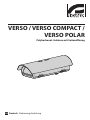
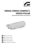
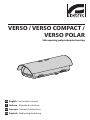
VERSO / VERSO COMPACT /
VERSO POLAR
Side opening polycarbonate housing
EN English - Instructions manual
IT Italiano - Manuale di istruzioni
FR Français - Manuel d'instructions
DE Deutsch - Bedienungslanleitung
VERSO / VERSO COMPACT /
VERSO POLAR
Side opening polycarbonate housing
EN English - Instructions manual
Contents
ENGLISH
1.1 Typographical conventions................................................................................................................................. 5
2 Notes on copyright and information on trademarks................................................. 5
3 Safety rules.................................................................................................................... 5
4 Identification................................................................................................................. 6
4.1 Product description and type designation.................................................................................................... 6
4.2 Product markings.................................................................................................................................................... 6
5 Preparing the product for use...................................................................................... 6
5.1 Contents and unpacking...................................................................................................................................... 6
5.2 Safely disposing of packaging material.......................................................................................................... 6
6 Installing and assembling............................................................................................. 7
6.1 Installation................................................................................................................................................................. 7
6.1.1 How to open the housing.................................................................................................................................................... 7
6.1.2 How to install the camera.................................................................................................................................................... 7
6.1.3 Connection to the power supply line.............................................................................................................................. 7
6.1.3.1 Type of cable.................................................................................................................................................................................................. 7
6.1.3.2 Attaching the housing................................................................................................................................................................................ 8
6.1.4 How to install the heater...................................................................................................................................................... 8
6.1.5 How to install the camera power supply........................................................................................................................ 9
6.1.6 How to install the blower..................................................................................................................................................... 9
6.1.6.1 100-240Vac power supply.......................................................................................................................................................................10
6.1.6.2 12Vdc or 24Vac power supply................................................................................................................................................................10
6.1.7 Cooling device.......................................................................................................................................................................10
6.1.8 Configuration for low temperatures..............................................................................................................................11
7 Maintaining and cleaning........................................................................................... 11
7.1 Window and plastic cover cleaning (PC).......................................................................................................11
8 Disposal of waste materials........................................................................................ 11
9 Technical specifications.............................................................................................. 11
9.1 VERSO........................................................................................................................................................................11
9.1.1 General......................................................................................................................................................................................11
9.1.2 Mechanical..............................................................................................................................................................................12
9.1.3 Electrical...................................................................................................................................................................................12
9.1.4 Environment...........................................................................................................................................................................12
9.1.5 Certifications...........................................................................................................................................................................12
9.2 VERSO COMPACT...................................................................................................................................................12
9.2.1 General......................................................................................................................................................................................12
9.2.2 Mechanical..............................................................................................................................................................................12
9.2.3 Electrical...................................................................................................................................................................................12
9.2.4 Environment...........................................................................................................................................................................12
9.2.5 Certifications...........................................................................................................................................................................12
9.3 VERSO POLAR..........................................................................................................................................................13
9.3.1 General......................................................................................................................................................................................13
9.3.2 Mechanical..............................................................................................................................................................................13
3
EN - English - Instructions manual
1 About this manual......................................................................................................... 5
EN - English - Instructions manual
9.3.3 Electrical...................................................................................................................................................................................13
9.3.4 Environment...........................................................................................................................................................................13
9.3.5 Certifications...........................................................................................................................................................................13
10 Technical drawings.................................................................................................... 13
4
3 Safety rules
Before installing and using this unit, please read this
manual carefully. Be sure to keep it handy for later
reference.
hh
1.1 Typographical conventions
DANGER!
High level hazard.
Risk of electric shock. Disconnect the
power supply before proceeding with any
operation, unless indicated otherwise.
gg
WARNING!
Medium level hazard.
This operation is very important for the
system to function properly. Please read
the procedure described very carefully and
carry it out as instructed.
hh
INFO
Description of system specifications.
We recommend reading this part carefully
in order to understand the subsequent
stages.
jj
The manufacturer declines all responsibility
for any damage caused by an improper use
of the appliances mentioned in this manual.
Furthermore, the manufacturer reserves
the right to modify its contents without any
prior notice. The documentation contained
in this manual has been collected with great
care, the manufacturer, however, cannot
take any liability for its use. The same thing
can be said for any person or company
involved in the creation and production of
this manual.
• The device must be installed only and exclusively
by qualified technical personnel.
• Before any technical work on the appliance,
disconnect the power supply.
• Do not use power supply cables that seem worn
or old.
• Never, under any circumstances, make any
changes or connections that are not shown in
this handbook: improper use of the appliance
can cause serious hazards, risking the safety of
personnel and of the installation.
2 Notes on copyright and
information on trademarks
• Use only original spare parts. Not original spare
parts could cause fire, electrical discharge or other
hazards.
The quoted names of products or companies are
trademarks or registered trademarks.
• Before proceeding with installation check the
supplied material to make sure it corresponds
to the order specification by examining the
identification labels ("4.2 Product markings", page 6).
• This device was designed to be permanently
installed on a building or on a suitable structure.
• When installing the device, comply with all the
national standards.
• The electrical system of the building on which
the device is to be installed must have a two-pole
protection circuit (circuit breaker) complete with
an automatic two-pole switch which provides
protection for earth fault current (circuit breaker
+ differential) with a minimum distance between
contacts of 3 mm.
• Any device which could be installed inside the
housing must comply with the current standards.
5
EN - English - Instructions manual
1 About this manual
EN - English - Instructions manual
4 Identification
4.1 Product description and
type designation
Innovative and stylish housing, entirely built in
technopolymer, and designed to simplify installation
and servicing, the VERSO/VERSO COMPACT ensures
total protection against all environmental conditions.
Due to opening from its side, accessibility to the
camera, lens and all its connections is made far easier.
Entirely manufactured from the newest, most
resistant technopolymer, VERSO/VERSO COMPACT
guarantees high impact resistance, weather
protection from external agents and UV rays. Its
weatherproof features are ensured by the neoprenerubber gaskets and the cable glands or installed with
an internal cable management bracket and optional
sealing rings.
VERSO/VERSO COMPACT offers the possibility of
various mounting options: wall mounted bracket,
cable managed bracket, or on a Pan & Tilt head which
includes the ability to house most combinations of
cameras and lenses.
A specific version of VERSO with a very efficient
cooling system is available for installation with IP
cameras and for high environmental temperature.
VERSO POLAR is provided with a high performance
heating system which allows the working/
functioning even at the most severe temperatures.
A wide range of accessories is available, including
sunshield, heater kit, blower, camera power supply,
heater fan-assistant or alarm tamper switch (only
VERSO). The accessories are supplied factory installed
or as a simple upgrade kit.
4.2 Product markings
See the label attached to the outside of the package.
6
5 Preparing the product
for use
Any change that is not expressly approved
by the manufacturer will invalidate the
guarantee.
hh
5.1 Contents and unpacking
When the product is delivered, make sure that the
package is intact and that there are no signs that it
has been dropped or scratched.
If there are obvious signs of damage, contact the
supplier immediately.
Keep the packaging in case you need to send the
product for repairs.
Check the contents to make sure they correspond
with the list of materials as below:
• Housing
• Housing equipment:
• Allen wrench
• Spacers
• Cable glands
• Screws and washers
• Screws for camera
• Instructions manual
5.2 Safely disposing of
packaging material
The packaging material can all be recycled. The
installer technician will be responsible for separating
the material for disposal, and in any case for
compliance with the legislation in force where the
device is to be used.
Bear in mind that if the material has to be returned
due to a fault, using the original packaging for its
transport is strongly recommended.
6 Installing and
assembling
01
03
EN - English - Instructions manual
02
Only specialised personnel should be
allowed to install and assemble the device.
hh
The housing where this device is installed
must be powered by 12Vdc or 24Vac
voltage.
hh
Turn off the power before performing any
operations.
hh
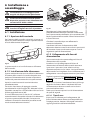
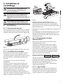
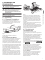
6.1 Installation
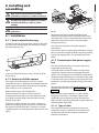
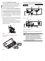
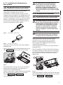
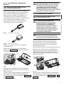
6.1.1 How to open the housing
To open the housing, loosen the 2 screws on the side,
turn the cover and the upper half of the body about
the opening hinge axis.
Fig. 02
Reposition the internal slide by tightening the
previously loosened screws. Place the camera with
the optics front side to a centimeter from the upper
edge of the housing in order to avoid damages
during the closing.
Close the housing after making the electrical
connections.
The camera’s power supply cable conductors must be
tied up next to the terminal. Make sure the signalling
and power supply cables are separated from each
other.
6.1.3 Connection to the power supply
line
This section describes how to connect the power
supply line to the housing.
Fig. 01
In this way there will be easy access to the inside of
the housing.
6.1.2 How to install the camera
This section describes how to install the camera
inside the housing. It should be remembered that the
power supply can be taken from the circuit supplied
after making sure it is correct one.
Open the housing as described before.
Extract the internal support slide by partially
loosening the fastening screws (01). Move the slide,
by sliding it until the holes coincide with the slide
locking screws (02).
Fasten the camera with the 1/4" screw; if necessary
place the insulating spacer between the camera and
the upper half of the slide (03). If necessary, use the
supplied spacers to correctly position the camera and
optics.
Insert the cables for the connection to the power
supply line inside the housing through the cable
glands. The cable glands are suitable for cables with a
diameter comprised between 5 and 10mm. The cable
inside the housing must be long enough to allow the
connection and the appropriate locking of the cable
glands.
Remove the conductors protective sheathing and
connect them to terminal J3 (Fig. 05, page 8 and Fig.
06, page 8).
Make sure the earth conductor is at least 10mm.
longer than the others. The power supply cable
conductors must be tied up next to the terminal.
Make sure the signalling and power supply cables are
separated from each other
6.1.3.1 Type of cable
The cable used for the connection to the power
supply line must be suitable for the intended use.
Comply with the current national standards on
electrical installations.
7
EN - English - Instructions manual
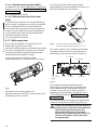
6.1.3.2 Attaching the housing
The housing must be attached using suitable means,
such as brackets or supports. The fastening means
must guarantee the mechanical seal when a force
equal to at least four times the weight of the device
is applied.
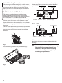
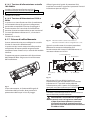
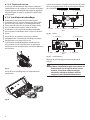
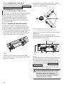
Insert the 2-pin connector at the end of the cable into
the correspondent support circuit socket, identified
by J2 HEATER (Fig. 05, page 8 and Fig. 06, page 8).
J2 - Heater
J6 - Blower
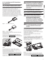
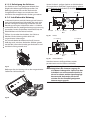
6.1.4 How to install the heater
This section describes how to install the heater
option in the dust-proof housings not provided
with. Heaters can be supplied with working voltages
of 12Vdc/24Vac or 115/230Vac and include the
pre-wired heating element suitable for the working
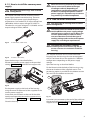
voltage, metal dissipators and kit fastening screws.
Open the housing as described before. Fix the heater
kit to the prearranged points on the body of the
housing.
J4 - OUT
Fig. 05
J3 - IN J1 - Camera
OUT
J5 - Power supply
VERSO.
J2 - Heater
J5 - Power supply
The pre-wired heating element should be positioned
between the 2 dissipators before attachment to
ensure contact and hence guarantee correct heat
diffusion.
J4 - OUT
Fig. 06
J3 - IN
J1 - Camera
OUT
J6 - Blower
VERSO COMPACT.
Reposition the internal support slide and close the
housing.
Fig. 03
Pass the heating wire into the provided seatings.
Fig. 04
8
The circuit is also able to provide the
power supply for a camera. While powering
the circuit from an external source, pay
attention to the type of working voltage
and use the correct power supply kit,
according to requirements.
hh
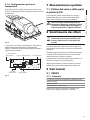
6.1.5 How to install the camera power
supply
When the circuit is powered by an external
source care must be taken to the type
of voltage used and, depending on
requirements, to the correct power supply
kit. When installing the optional camera
power supply it is not necessary to remove
any previously installed component.
hh
This chapter describes how to install the camera
power supply option into the housing. There are
2 types of camera power supply depending on
requirements. One model has an input voltage from
100-240Vac with an output voltage of 12Vdc, 1A.
The other has an input voltage of 115/230Vac and an
output voltage of 24Vac, 400mA.
EN - English - Instructions manual
Not applicable to housings with installed
cooling device.
hh
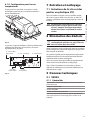
6.1.6 How to install the blower
Not applicable to housings with installed
cooling device.
hh
The terminal board marked J4 can be used
to take off the main power supply voltage
coming from an external source. When the
circuit is powered by an external source
care must be taken to check the type of
working voltage and use the correct power
supply kit, according to requirements.
hh
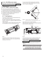
Fig. 07
IN 100-240Vac - OUT 12Vdc.
The blower kit should be assembled
according to the instructions (Fig. 05) to
ensure a correct air circulation inside the
housing.
hh
Fig. 08
IN 230Vac - OUT 24Vac.
Open the housing as described before.
Position the camera power supply in the provided
seating (Fig. 04, page 8) parallel to the support ribs.
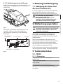
This chapter describes how to install the blower
kit option into the housings that are not equipped
with it. The blower kit can be supplied in 3 different
configurations depending on the power supply
voltage.
Open the housing as described before.
Fix the blower inside the body of the housing, using
the corner bracket and the supplied screws. One
positioning option is possible for the 420mm version
(01) and 2 for the 360mm version (02).
01
Fig. 09
Fix the power supply to the body of the housing
using the corner bracket and screws supplied in the
camera power supply kit.
Insert the 6-pin connector at the end of the cable
into the correspondent one on the support circuit,
identified by J5 (Fig. 05, page 8 and Fig. 06, page 8).
Close the housing.
02
Fig. 10
Insert the 2 pin connector at the end of the cable into
the corresponding one indicated by J6 (FAN) on the
support circuit (Fig. 05, page 8 and Fig. 06, page 8).
9
Install the camera power supply supplied with the
blower kit as described in the chapter "6.1.5 How to
install the camera power supply", page 9.
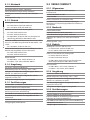
To guarantee the IP44 weatherproof, install the
housing on the support following the inclination
limits as shown in the picture.
Close the housing.
6.1.6.2 12Vdc or 24Vac power supply
45°
0˚
In this housing the blower kit is supplied with a
connector fitted with the appropriate connections to
make the support circuit compatible with operation
at the power supply voltage available. This connector
should be inserted into the correspondent one
marked J5, on the supplied circuit.
45°
EN - English - Instructions manual
6.1.6.1 100-240Vac power supply
Close the housing.
6.1.7 Cooling device
This section describes how to connect the housing
with installed cooling device.
No other components need installing inside these
models, as each one is supplied complete with all the
necessary parts.
Special attention must be paid to the position of the
air intake filter fins when installing the housing.
Fig. 12
Maximal rotation on the transversal axis: 0˚.
Maximal inclination on the longitudinal axis: +/- 45˚.
Open the housing as explained above.
Make the electric connections for the cooling device
to the terminal marked J8 FAN.
J3 - Heater
J7 - Power supply
IN
OUT
J5 - Camera
OUT
J1 - IN
J2 - OUT
J8 - Blower
Fig. 11
Fig. 13
Depending on the inclination of the housing, the
direction of the fins must be such to prevent water
entering in case of rain.
In this circuit the camera can be powered from the
terminal marked J2. The power for the optional
heating system can be taken from the terminal
marked J3 HEATER ("6.1.3 Connection to the power
supply line", page 7).
Close the housing following these instructions in
reverse.
If the circuit is powered from an external
source, pay special attention to the voltage,
as the housings with this device must only
be powered with 12Vdc or 24V AC voltage.
hh
10
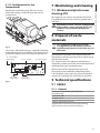
7 Maintaining and cleaning
6.1.8 Configuration for low
temperatures
7.1 Window and plastic cover
cleaning (PC)
We suggest to use neutral soap diluted with water
or specific products for lens cleaning applied with a
soft cloth.
Avoid ethyl alcohol, solvents, hydrogenated
hydrocarbide, strong acid and alkali. Such
products may irreparably damage the
surface.
hh
8 Disposal of waste
materials
Fig. 14
The version with triple heating is supplied completely
wired directly by the manufacturer. The relative circuit
mounted in the housing is illustrated in the diagram.
J6 - Camera OUT
24Vac/12Vdc
J1-J2-J3 - Heater
J8 - Power supply
This symbol mark and recycle system
are applied only to EU countries and not
applied to the countries in the other area of
the world.
nn
Your product is designed and manufactured with
high quality materials and components which can be
recycled and reused.
This symbol means that electrical and electronic
equipment, at their end-of-life, should be disposed of
separately from your household waste.
Please dispose of this equipment at your local
Community waste collection or Recycling centre.
J10 - OUT
230Vac/24Vac
Fig. 15
J7 - IN
230Vac/24Vac
In the European Union there are separate collection
systems for used electrical and electronic products.
9 Technical specifications
9.1 VERSO
9.1.1 General
Entirely constructed from technopolymer
(polycarbonate)
Sunshield in ABS
RAL9002 Colour
Stainless steel external screws
Supplied with instruction manual, desiccant bag,
accessories for camera and lens mounting
11
EN - English - Instructions manual
Besides the standard housing, there is a version
with triple heating, suitable for operation at low
temperatures.
9.1.2 Mechanical
EN - English - Instructions manual
3xM16 cable glands
Polycarbonate window (WxH): 105x64mm (4.1x2.5in)
Internal usable area (WxH): 70x70mm (2.7x2.7in)
Internal usable length with and without accessories:
270mm (10.6in)
9.2 VERSO COMPACT
9.2.1 General
Entirely constructed from technopolymer
(polycarbonate)
Sunshield in ABS
Unit weight: 1.5kg / 3.3lb
RAL9002 Colour
9.1.3 Electrical
Supplied with instruction manual, desiccant bag,
accessories for camera and lens mounting
Heater Ton 15°C±3°C (59°F ±37°F) Toff 22°C±3°C (71°F
±37°F)
9.2.2 Mechanical
-- IN 12Vdc/24Vac, consumption 20W max
-- IN 115/230Vac, consumption 40W max
Heater fan assistant, continuous duty
-- IN 12Vdc, consumption 4W max
-- IN 24Vac, consumption 4W max
-- IN 100-240Vac, consumption 4W max, with wide
range power supply IN 100-240Vac/12Vdc
Blower with thermostat air filter, Ton 35°C±3°C
(95°F±37°F) Toff 20°C±3°C (71°F±37°F) with wide range
power supply IN 100-240Vac - OUT 12Vdc, out 1A
-- IN 110-240Vac, consumption 4W max
Blower with thermostat Ton 35°C±3°C (95°F±37°F) Toff
20°C±3°C (71°F±37°F) for version with double filter
-- IN 12Vdc, consumption 4W max
-- IN 24Vac, consumption 4W max
Camera power supply
-- IN 100-240Vac - OUT 12Vdc, 50/60 Hz, 1A
-- IN 230Vac - OUT 24Vac, 50/60Hz, 400mA
9.1.4 Environment
Indoor / Outdoor
Operating temperature with heater: -20°C / +60°C (-4°F
/ +140°F)
Very good resistance to the following chemical agents:
basics, alcohols, gasses, hydrocarbon
Stainless steel external screws
2xM16 cable glands
Polycarbonate window (WxH): 98x55mm (3.9x2.2in)
Internal usable area (WxH): 63x63mm (2.5x2.5in)
Internal usable length with and without accessories:
210mm (8.3in)
Unit weight: 1.1kg / 2.4lb
9.2.3 Electrical
Heater Ton 15°C±3°C (59°F ±37°F) Toff 22°C±3°C (71°F
±37°F)
-- IN 12Vdc/24Vac, consumption 20W max
-- IN 115/230Vac, consumption 40W max
Heater fan assistant, continuous duty
-- IN 12Vdc, consumption 4W max
-- IN 24Vac, consumption 4W max
-- IN 100-240Vac, consumption 4W max, with wide
range power supply IN 100-240Vac/12Vdc
Camera power supply
-- IN 100-240Vac - OUT 12Vdc, 50/60 Hz, 1A
-- IN 230Vac - OUT 24Vac, 50 Hz, 400mA
9.2.4 Environment
Indoor / Outdoor
Operating temperature with heater: -20°C / +60°C (-4°F
/ +140°F)
Good resistance: organic and inorganic acids, oils
Very good resistance to the following chemical agents:
basics, alcohols, gasses, hydrocarbon
Low resistance: solvents
Good resistance: organic and inorganic acids, oils
9.1.5 Certifications
Low resistance: solvents
CE EN61000-6-3, EN60950-1, EN50130-4
9.2.5 Certifications
IP66/IP67 EN60529 with cable glands
IP66/IP67 EN60529 with special gaskets and bracket with
internal cable channel
CE EN61000-6-3, EN60950-1, EN50130-4
IP66/IP67 EN60529 with cable glands
IP55 EN60529 with bracket with internal cable channel
IP66/IP67 EN60529 with special gaskets and bracket with
internal cable channel
IP44 EN60529 with cooling blower and double filter
IP55 EN60529 with bracket with internal cable channel
V1 fire-self extinguish compliance UL94
V1 fire-self extinguish compliance UL94
Impact resistance IK10 EN62262
Impact resistance IK10 EN62262
12
9.3 VERSO POLAR
9.3.4 Environment
Indoor / Outdoor
9.3.1 General
Sunshield in ABS
Very good resistance to the following chemical agents:
basics, alcohols, gasses, hydrocarbon
RAL9002 Colour
Good resistance: organic and inorganic acids, oils
Stainless steel external screws
Low resistance: solvents
Supplied with instruction manual, desiccant bag,
accessories for camera and lens mounting
9.3.5 Certifications
9.3.2 Mechanical
IP66/IP67 EN60529 with cable glands
CE EN61000-6-3, EN60950-1, EN50130-4
3xM16 cable glands in nickel-plated brass
Polycarbonate window (WxH): 105x64mm (4.1x2.5in)
IP66/IP67 EN60529 with special gaskets and bracket with
internal cable channel
Internal usable area (WxH): 70x70mm (2.7x2.7in)
IP55 EN60529 with bracket with internal cable channel
Internal usable length with and without accessories:
270mm (10.6in)
V1 fire-self extinguish compliance UL94
Impact resistance IK10 EN62262
Unit weight: 1.5kg / 3.3lb
9.3.3 Electrical
Heater Ton 15°C±3°C (59°F ±37°F) Toff 22°C±3°C (71°F
±37°F)
-- IN 12Vdc/24Vac, consumption 60W max
-- IN 115/230Vac, consumption 120W max
Camera power supply
-- IN 100-240Vac - OUT 12Vdc, 50/60 Hz, 1A
-- IN 230Vac - OUT 24Vac, 50/60Hz, 400mA
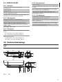
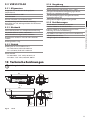
10 Technical drawings
The values are in millimeters.
270
70
USABLE AREA
USABLE
AREA
A-A
466
70
jj
B-B
B
B
77
100
Fig. 16
A
15
101
113
A
26
156
VERSO
13
EN - English - Instructions manual
Operating temperature with heater: -55°C / +60°C (-67°F
/ +140°F)
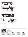
Entirely constructed from technopolymer
(polycarbonate)
63
USABLE AREA
USABLE
AREA
A-A
400
63
210
B-B
A
94
106
B
18
B
A
15
94
135
Fig. 17
270
70
USABLE AREA
USABLE
AREA
A-A
466
70
VERSO COMPACT
B-B
A
B
156
Fig. 18
VERSO POLAR
VIDEOTEC S.p.A.
www.videotec.com
Printed in Italy
MNVCHPVB_1006_EN
A
15
101
113
B
VERSO / VERSO COMPACT /
VERSO POLAR
Custodia in policarbonato ad apertura laterale
IT Italiano - Manuale di istruzioni
Sommario
ITALIANO
1 Informazioni sul presente manuale............................................................................. 5
1.1 Convenzioni tipografiche..................................................................................................................................... 5
4.1 Descrizione e designazione del prodotto...................................................................................................... 6
4.2 Marcatura del prodotto......................................................................................................................................... 6
5 Preparazione del prodotto per l'utilizzo..................................................................... 6
5.1 Contenuto e disimballaggio................................................................................................................................ 6
5.2 Smaltimento in sicurezza dei materiali di imballaggio.............................................................................. 6
6 Installazione e assemblaggio....................................................................................... 7
6.1 Installazione.............................................................................................................................................................. 7
6.1.1 Apertura della custodia........................................................................................................................................................ 7
6.1.2 Installazione della telecamera............................................................................................................................................ 7
6.1.3 Collegamento alla linea di alimentazione...................................................................................................................... 7
6.1.3.1 Tipo di cavo..................................................................................................................................................................................................... 7
6.1.3.2 Fissaggio della custodia............................................................................................................................................................................. 8
6.1.4 Installazione del riscaldamento......................................................................................................................................... 8
6.1.5 Installazione dell’alimentatore per telecamera............................................................................................................ 9
6.1.6 Installazione del ventilatore................................................................................................................................................ 9
6.1.6.1 Tensione di alimentazione custodia 100-240Vac............................................................................................................................10
6.1.6.2 Tensione d’alimentazione 12Vdc o 24Vac.........................................................................................................................................10
6.1.7 Sistema di raffreddamento................................................................................................................................................10
6.1.8 Configurazione per basse temperature........................................................................................................................11
7 Manutenzione e pulizia.............................................................................................. 11
7.1 Pulizia del vetro e delle parti in plastica (PC)...............................................................................................11
8 Smaltimento dei rifiuti................................................................................................ 11
9 Dati tecnici................................................................................................................... 11
9.1 VERSO........................................................................................................................................................................11
9.1.1 Generale...................................................................................................................................................................................11
9.1.2 Meccanica................................................................................................................................................................................12
9.1.3 Elettrico.....................................................................................................................................................................................12
9.1.4 Ambiente.................................................................................................................................................................................12
9.1.5 Certificazioni...........................................................................................................................................................................12
9.2 VERSO COMPACT...................................................................................................................................................12
9.2.1 Generale...................................................................................................................................................................................12
9.2.2 Meccanica................................................................................................................................................................................12
9.2.3 Elettrico.....................................................................................................................................................................................12
9.2.4 Ambiente.................................................................................................................................................................................12
9.2.5 Certificazioni...........................................................................................................................................................................12
9.3 VERSO POLAR..........................................................................................................................................................13
9.3.1 Generale...................................................................................................................................................................................13
9.3.2 Meccanica................................................................................................................................................................................13
3
IT - Italiano - Manuale di istruzioni
2 Note sul copyright e informazioni sui marchi commerciali....................................... 5
3 Norme di sicurezza........................................................................................................ 5
4 Identificazione............................................................................................................... 6
9.3.3 Elettrico.....................................................................................................................................................................................13
9.3.4 Ambiente.................................................................................................................................................................................13
9.3.5 Certificazioni...........................................................................................................................................................................13
IT - Italiano - Manuale di istruzioni
10 Disegni tecnici........................................................................................................... 13
4
1 Informazioni sul presente
manuale
1.1 Convenzioni tipografiche
PERICOLO!
Pericolosità elevata.
Rischio di scosse elettriche. Togliere
l'alimentazione prima di procedere con le
operazioni, salvo diversa indicazione.
gg
ATTENZIONE!
Pericolosità media.
L'operazione è molto importante per il
corretto funzionamento del sistema. Si
prega di leggere attentamente la procedura
indicata e di eseguirla secondo le modalità
previste.
hh
INFO
Descrizione delle caratteristiche del
sistema.
Si consiglia di leggere attentamente per
comprendere le fasi successive.
jj
2 Note sul copyright e
informazioni sui marchi
commerciali
I nomi di prodotto o di aziende citati sono marchi
commerciali o marchi commerciali registrati
appartenenti alle rispettive società.
Il produttore declina ogni responsabilità
per eventuali danni derivanti da un
uso improprio delle apparecchiature
menzionate in questo manuale. Si
riserva inoltre il diritto di modificarne il
contenuto senza preavviso. Ogni cura è
stata posta nella raccolta e nella verifica
della documentazione contenuta in questo
manuale, tuttavia il produttore non può
assumersi alcuna responsabilità derivante
dall'utilizzo della stessa. Lo stesso dicasi
per ogni persona o società coinvolta nella
creazione e nella produzione di questo
manuale.
hh
• L'installazione e la manutenzione del dispositivo
deve essere eseguita solo da personale tecnico
qualificato.
• Prima di effettuare interventi tecnici
sull'apparecchio togliere l'alimentazione elettrica.
• Non utilizzare cavi di alimentazione con segni di
usura o invecchiamento.
• Non effettuare per nessun motivo alterazioni o
collegamenti non previsti in questo manuale:
l'uso di apparecchi non idonei può portare a
gravi pericoli per la sicurezza del personale e
dell'impianto.
• Utilizzare solo parti di ricambio originali. Pezzi di
ricambio non originali potrebbero causare incendi,
scariche elettriche o altri pericoli.
• Prima di procedere con l'installazione controllare
che il materiale fornito corrisponda alle specifiche
richieste esaminando le etichette di marcatura ("4.2
Marcatura del prodotto", pagina 6).
• Il dispositivo è stato concepito per essere installato
in modo permanente ad un edificio o ad una
struttura adeguata.
• Si devono rispettare le normative nazionali per
l'installazione del dispositivo.
• L'impianto elettrico dell'edificio dove viene
installato il dispositivo deve essere provvisto di
circuito di protezione (magneto termico) bipolare,
che deve comprendere un interruttore bipolare di
tipo automatico che preveda anche la protezione
della corrente di guasto verso terra (magneto
termico + differenziale) con distanza minima tra i
contatti di 3mm.
• Gli apparecchi installabili all'interno della custodia
devono essere conformi alle norme vigenti.
5
IT - Italiano - Manuale di istruzioni
Prima di installare e utilizzare questa unità, leggere
attentamente questo manuale. Conservare questo
manuale a portata di mano come riferimento futuro.
3 Norme di sicurezza
4 Identificazione
IT - Italiano - Manuale di istruzioni
4.1 Descrizione e designazione
del prodotto
Custodia moderna ed innovativa, progettata per
semplificare l’installazione ed il servizio, VERSO/
VERSO COMPACT garantisce una protezione totale a
tutte le condizioni ambientali. La sua apertura laterale
facilita ampiamente l’accessibilità alla telecamera, alle
ottiche ed a tutte le sue connessioni.
Costruita interamente in resistente tecnopolimero,
VERSO/VERSO COMPACT assicura un’elevata
resistenza agli impatti, un’alta protezione contro
gli agenti atmosferici ed ai raggi UV. La sua tenuta
stagna è mantenuta dalle guarnizioni in gomma
neoprene e da pressacavi o dagli anelli di tenuta
accessori, se installata con supporto con passaggio
interno dei cavi.
VERSO/VERSO COMPACT offre diverse varianti
di montaggio, supporto a parete, supporto con
passaggio interno cavi e brandeggio; riesce inoltre
ad alloggiare la maggior parte di combinazioni di
telecamere ed ottiche.
È disponibile una versione della VERSO con un
sistema di ventilazione altamente efficiente per
applicazioni con telecamere IP e per temperature
elevate.
VERSO POLAR è equipaggiata di un sistema di
riscaldamento che garantisce un funzionamento
ottimale anche alle temperature più rigide.
È disponibile un’ampia gamma di accessori, che
include il tettuccio, il riscaldamento, il ventilatore,
l’alimentatore per telecamera ed il contatto d’allarme
antiapertura (solo VERSO). Gli accessori sono forniti
come semplici kit di montaggio per una facile
installazione.
4.2 Marcatura del prodotto
Vedere l’etichetta posta sull’esterno dell’imballo.
6
5 Preparazione del
prodotto per l'utilizzo
Qualsiasi cambiamento non espressamente
approvato dal costruttore fa decadere la
garanzia.
hh
5.1 Contenuto e disimballaggio
Alla consegna del prodotto verificare che l'imballo
sia integro e non abbia segni evidenti di cadute o
abrasioni.
In caso di evidenti segni di danno all'imballo
contattare immediatamente il fornitore.
Conservare l'imballo nel caso sia necessario inviare il
prodotto in riparazione.
Controllare che il contenuto sia rispondente alla lista
del materiale sotto indicata:
• Custodia
• Dotazione per custodia:
• Chiave a brugola
• Distanziali
• Pressacavi
• Viti e rondelle
• Viti per telecamera
• Manuale di istruzioni
5.2 Smaltimento in sicurezza dei
materiali di imballaggio
I materiali d'imballo sono costituiti interamente da
materiale riciclabile. Sarà cura del tecnico installatore
smaltirli secondo le modalità di raccolta differenziata
o comunque secondo le norme vigenti nel Paese di
utilizzo.
Si ricorda comunque che in caso di ritorno di
materiale con malfunzionamenti è consigliato
l'imballaggio originale per il trasporto.
6 Installazione e
assemblaggio
01
03
02
L'installazione e l'assemblaggio vanno
eseguiti solo da personale specializzato.
hh
Prima di eseguire qualsiasi operazione
ricordarsi di togliere tensione al prodotto.
hh
6.1 Installazione
6.1.1 Apertura della custodia
Per l’apertura della custodia, svitare le 2 viti poste sul
fianco, far ruotare tettuccio e corpo superiore attorno
all’asse delle cerniere di apertura.
Fig. 02
Riposizionare la slitta interna fissando le viti
precedentemente allentate. Collocare la telecamera
con la parte anteriore dell’ottica ad un centimetro dal
bordo superiore della custodia al fine di evitare danni
in fase di chiusura.
Chiudere la custodia dopo aver effettuato le
connessioni elettriche.
I conduttori del cavo di alimentazione della
telecamera devono essere fissati tra loro in prossimità
del morsetto. Avere cura di tenere separati i cavi di
segnale da quelli di alimentazione.
6.1.3 Collegamento alla linea di
alimentazione
Questa sezione descrive come collegare la linea di
alimentazione alla custodia.
Fig. 01
In questo modo vi sarà un facile accesso all’interno
della custodia.
6.1.2 Installazione della telecamera
Questa sezione descrive come installare la telecamera
all’interno della custodia. Si ricorda che può essere
prelevata l’alimentazione dal circuito in dotazione
verificando preventivamente che sia quella corretta.
Aprire la custodia come da istruzioni descritte
precedentemente.
Estrarre la slitta interna di appoggio svitando
parzialmente le viti di fissaggio (01). Muovere la slitta
facendola scorrere fino a far coincidere i fori con le viti
di bloccaggio della stessa (02).
Fissare la telecamera con la vite da 1/4"; collocare
eventualmente il distanziale isolante tra la telecamera
e la parte superiore della slitta (03). Se necessario
utilizzare i distanziali in dotazione per collocare nel
modo corretto telecamera e ottica.
Introdurre i cavi di collegamento alla linea di
alimentazione all'interno della custodia attraverso
i pressacavi. I pressacavi sono adatti a cavi con
diametro compreso tra 5 e 10mm. Lasciare all'interno
della custodia una lunghezza di cavo sufficiente per il
collegamento e serrare opportunamente i pressacavi.
Togliere la guaina di protezione dei conduttori e
collegarli al morsetto J3 (Fig. 05, pagina 8 e Fig. 06,
pagina 8).
Avere cura di lasciare il conduttore di terra più lungo
degli altri di almeno 10mm. I conduttori del cavo
di alimentazione devono essere fissati tra loro in
prossimità del morsetto.
Avere cura di tenere separati i cavi di alimentazione
da quelli di segnale.
6.1.3.1 Tipo di cavo
Il tipo cavo da utilizzare per il collegamento alla
linea di alimentazione deve essere compatibile con
l'impiego previsto. Attenersi alle regole nazionali in
vigore riguardo le installazioni elettriche.
7
IT - Italiano - Manuale di istruzioni
Le versioni di custodia munite di questo
dispositivo possono essere alimentate solo
con tensioni di 12Vdc o 24Vac.
hh
IT - Italiano - Manuale di istruzioni
6.1.3.2 Fissaggio della custodia
La custodia deve essere fissata con mezzi adeguati
mediante staffe o supporti. I mezzi di fissaggio
devono garantire la tenuta meccanica applicando
una forza pari almeno a quattro volte il peso
complessivo dell’ apparecchiatura.
Inserire il connettore a 2 poli posto all’estremità del
cavo nel suo corrispondente sul circuito di appoggio,
indicato con la scritta J2 HEATER (Fig. 05, pagina 8 e Fig.
06, pagina 8).
J2 - Riscaldamento
J6 - Ventilatore
6.1.4 Installazione del riscaldamento
Questa sezione descrive come installare l’opzione
riscaldamento nelle custodie che ne sono sprovviste.
Il riscaldamento può essere fornito con tensioni di
lavoro di 12Vdc/24Vac o 115/230Vac e comprende,
a seconda della tensione di utilizzo, la resistenza di
riscaldamento precablata, i dissipatori metallici e le
viti per il fissaggio del kit.
Aprire la custodia seguendo le indicazioni descritte
precedentemente. Fissare il kit di riscaldamento nei
punti predisposti sul corpo custodia.
J4 - OUT
Fig. 05
J3 - IN J1 - Camera
OUT
J5 - Alimentatore
VERSO.
J2 - Riscaldamento
J5 - Alimentatore
La resistenza precablata deve essere interposta fra
i 2 dissipatori prima del fissaggio per garantirne il
contatto e assicurare in questo modo una corretta
diffusione del calore.
J4 - OUT
Fig. 06
J3 - IN
J1 - Camera
OUT
J6 - Ventilatore
VERSO COMPACT.
Riposizionare la slitta interna di appoggio e chiudere
la custodia.
Fig. 03
Passare il filo del riscaldamento nelle sedi
predisposte.
Fig. 04
8
Nel circuito c’è anche la possibilità
di prelevare l’alimentazione per una
telecamera. Alimentando il circuito da una
sorgente esterna è necessario prestare
attenzione al tipo di tensione utilizzata e
adottare, a seconda delle esigenze, il kit di
alimentazione corretto.
hh
6.1.5 Installazione dell’alimentatore
per telecamera
Alimentando il circuito da una sorgente
esterna è necessario prestare attenzione al
tipo di tensione utilizzata e a seconda delle
esigenze, il kit di alimentazione corretto.
Per montare l’opzione alimentatore non è
necessario rimuovere alcun componente
preinstallato.
hh
Non applicabile nelle custodie munite di
sistema per il raffreddamento installato.
hh
Fig. 07
Fig. 08
IN 100-240Vac - OUT 12Vdc.
IN 230Vac - OUT 24Vac.
Aprire la custodia seguendo le indicazioni descritte
precedentemente.
Posizionare l’alimentatore nella sede predisposta
all’alloggiamento (Fig. 04, pagina 8) in corrispondenza
delle nervature di sostegno.
6.1.6 Installazione del ventilatore
Non applicabile nelle custodie munite di
sistema per il raffreddamento installato.
hh
In corrispondenza della morsettiera
indicata con J4 è possibile prelevare la
tensione di alimentazione principale
derivante da una sorgente esterna.
Alimentando il circuito da una sorgente
esterna è necessario prestare attenzione al
tipo di tensione utilizzata e a seconda delle
esigenze, il kit di alimentazione corretto.
hh
Il ventilatore deve essere montato come
da istruzioni per garantire una corretta
circolazione dell’aria all’interno della
custodia.
hh
Questa sezione descrive come installare l’opzione
ventilatore nelle custodie che ne sono sprovviste.
Il kit di ventilazione può essere fornito in 3
configurazioni differenti a seconda della tensione di
alimentazione disponibile.
Aprire la custodia come da istruzioni descritte
precedentemente.
Fissare il ventilatore, tramite la staffetta angolare di
supporto, all’interno del corpo custodia utilizzando
le apposite viti in dotazione. Nella versione in
420mm (01) é possibile una sola regolazione e 2 nella
versione in 360mm (02).
01
Fig. 09
02
Fissare l’alimentatore al corpo della custodia
utilizzando l’apposita staffetta ad angolo e le viti
fornite nel kit di alimentazione.
Inserire il connettore a 6 poli posto all’estremità del
cavo nel suo corrispondente, sul circuito di appoggio,
indicato con J5 (Fig. 05, pagina 8 e Fig. 06, pagina 8).
Chiudere la custodia.
Fig. 10
Inserire il connettore a 2 poli posto all’estremità del
cavo nel suo corrispondente indicato con J6 (FAN) sul
circuito di appoggio (Fig. 05, pagina 8 e Fig. 06, pagina 8).
9
IT - Italiano - Manuale di istruzioni
Questa sezione descrive come installare l’opzione
alimentatore all’interno della custodia. Gli
alimentatori che possono essere installati sono di
2 categorie a seconda delle esigenze. Un modello
può avere una tensione di ingresso da 100-240Vac
con una tensione in uscita pari a 12Vdc, 1A. L’altra
possibilità prevede un alimentatore di diverso tipo
che può avere una tensione di ingresso di 115/230Vac
con tensione in uscita pari a 24Vac, 400mA.
6.1.6.1 Tensione di alimentazione custodia
100-240Vac
Chiudere la custodia.
6.1.6.2 Tensione d’alimentazione 12Vdc o
24Vac
45°
0˚
In questo caso viene fornito con il kit di ventilazione
un connettore dotato di opportuni collegamenti
per rendere compatibile il circuito di appoggio al
funzionamento con la tensione di alimentazione
presente. Questo connettore deve essere inserito nel
suo corrispondente indicato con J5, sul circuito in
dotazione.
45°
IT - Italiano - Manuale di istruzioni
Installare l’alimentatore fornito con il kit di
ventilazione come descritto nel capitolo "6.1.5
Installazione dell’alimentatore per telecamera", pagina 9.
Al fine di garantire il grado di protezione IP44,
installare la custodia al supporto rispettando i limiti di
inclinazione riportati in figura.
Chiudere la custodia.
6.1.7 Sistema di raffreddamento
Questa sezione descrive come collegare le custodie
munite di sistema di raffreddamento.
In queste versioni non è necessario collocare alcun
componente all’interno perché vengono fornite
complete di tutto il necessario, a seconda del modello
richiesto.
Fig. 12
Massima rotazione sull'asse trasversale: 0˚.
Massima inclinazione sull'asse longitudinale: +/- 45˚.
Aprire la custodia come da istruzioni precedenti.
Effettuare le connessioni elettriche per il
funzionamento del sistema di raffreddamento sul
morsetto indicato con J8 FAN.
J3 - Riscaldamento
È importante prestare attenzione alla disposizione
delle alette del filtro d’ingresso aria nel momento
dell’installazione.
IN
J7 - Alimentatore
J5 - Camera
OUT
J1 - IN
J2 - OUT
J8 - Ventilatore
Fig. 13
OUT
Fig. 11
Il loro orientamento, in funzione dell’angolo di
inclinazione della custodia, deve prevenire la
penetrazione dell’acqua in caso di pioggia.
Nel circuito c’è la possibilità di prelevare
l’alimentazione per una telecamera sul morsetto
indicato con J2. È possibile anche prelevare
l’alimentazione per il sistema di riscaldamento
opzionale, morsetto indicato con J3 HEATER ("6.1.4
Installazione del riscaldamento", pagina 8).
Chiudere la custodia operando in maniera inversa a
quanto descritto precedentemente.
Alimentando il circuito da una sorgente
esterna è necessario prestare attenzione
al tipo di tensione utilizzata.Le versioni
di custodia munite di questo dispositivo
possono essere alimentate solo con tensioni
di 12Vdc o 24Vac.
hh
10
6.1.8 Configurazione per basse
temperature
Oltre alle custodia standard esiste una versione con
triplo riscaldamento idonea al funzionamento a basse
temperature.
7 Manutenzione e pulizia
7.1 Pulizia del vetro e delle parti
in plastica (PC)
IT - Italiano - Manuale di istruzioni
Si consigliano saponi neutri diluiti con acqua o
prodotti specifici per la pulizia delle lenti degli
occhiali con l’utilizzo di un panno morbido.
Sono da evitare alcool etilico,solventi,
idrocarburi idrogenati, acidi forti e alcali.
L’utilizzo di detti prodotti danneggia in
modo irreparabile la superficie trattata.
hh
8 Smaltimento dei rifiuti
Questo simbolo e il sistema di riciclaggio
sono validi solo nei paesi dell'EU e non
trovano applicazione in altri paesi del
mondo.
nn
Fig. 14
La versione con il triplo riscaldamento viene fornita
direttamente dal produttore completamente
cablata. Il relativo circuito presente nella custodia è
rappresentato in figura.
J6 - Camera OUT
24Vac/12Vdc
J1-J2-J3 - Riscaldamento J8 - Alimentatore
Il vostro prodotto è stato costruito da materiali e
componenti di alta qualità, che sono riutilizzabili o
riciclabili.
Prodotti elettrici ed elettronici che portano questo
simbolo alla fine dell'uso devono essere smaltiti
separatamente dai rifiuti casalinghi.
Vi preghiamo di smaltire questo apparecchio in un
Centro di raccolta o in un'Ecostazione.
Nell'Unione Europea esistono sistemi di raccolta
differenziata per prodotti elettrici ed elettronici.
9 Dati tecnici
J10 - OUT
230Vac/24Vac
Fig. 15
J7 - IN
230Vac/24Vac
9.1 VERSO
9.1.1 Generale
Costruita in resistente tecnopolimero (policarbonato)
Tettuccio in ABS
Colore RAL9002
Viteria esterna in acciaio Inox
Fornita con manuale di istruzioni, sacchetto sale,
accessori montaggio telecamera e obiettivo
11
9.1.2 Meccanica
3 pressacavi M16
Finestra policarbonato (WxH): 105x64mm
Dimensioni utili interne (WxH): 70x70mm
IT - Italiano - Manuale di istruzioni
Lunghezza utile interna con e senza accessori: 270mm
Peso unitario: 1.5kg
9.1.3 Elettrico
Riscaldamento Ton 15°C±3°C Toff 22°C±3°C
-- IN 12Vdc/24Vac, consumo 20W max
-- IN 115/230Vac, consumo 40W max
Ventilatore a ciclo continuo per assistenza riscaldamento
-- IN 12Vdc, consumo 4W max
-- IN 24Vac, consumo 4W max
-- IN 100-240Vac, consumo 4W max, completo di
alimentatore wide range IN 100-240Vac/12Vdc
Ventilatore con filtro aria e termostato, Ton 35°C±3°C Toff
20°C±3°C, con alimentatore wide range IN 100-240Vac OUT 12Vdc
-- IN 110-240Vac, consumo 4W max
Ventilatore con termostato Ton 35°C±3°C Toff 20°C±3°C
per modelli con doppio filtro per ricambio aria
9.2 VERSO COMPACT
9.2.1 Generale
Costruita in resistente tecnopolimero (policarbonato)
Tettuccio in ABS
Colore RAL9002
Viteria esterna in acciaio Inox
Fornita con manuale di istruzioni, sacchetto sale,
accessori montaggio telecamera e obiettivo
9.2.2 Meccanica
2 pressacavi M16
Finestra policarbonato (WxH): 98x55mm
Dimensioni utili interne (WxH): 63x63mm
Lunghezza utile interna con o senza accessori: 210mm
Peso unitario: 1.1kg
9.2.3 Elettrico
Riscaldamento Ton 15°C±3°C Toff 22°C±3°C
-- IN 12Vdc/24Vac, consumo 20W max
-- IN 115/230Vac, consumo 40W max
Ventilatore a ciclo continuo per assistenza riscaldamento
-- IN 12Vdc, consumo 4W max
-- IN 12Vdc, consumo 4W max
-- IN 24Vac, consumo 4W max
-- IN 24Vac, consumo 4W max
Alimentatore per telecamera
-- IN 100-240Vac - OUT 12Vdc, 50/60 Hz, 1A
-- IN 230Vac - OUT 24Vac, 50/60Hz, 400mA
9.1.4 Ambiente
Interno / Esterno
Temperatura d’esercizio con riscaldamento: -20°C / +60°C
Resistenza molto buona ai seguenti agenti chimici: basi,
alcoli, gas, idrocarburi
Resistenza buona: acidi organici e inorganici, olii
Resistenza bassa: solventi
9.1.5 Certificazioni
CE EN61000-6-3, EN60950-1, EN50130-4
IP66/IP67 EN60529 con pressacavi
IP66/IP67 EN60529 con anelli di tenuta e supporto con
passaggio interno cavi
IP55 EN60529 con supporto con passaggio interno cavi
IP44 EN60529 per modelli con doppio filtro per ricambio
d’aria
-- IN 100-240Vac, consumo 4W max (completo di
alimentatore wide range IN 100-240Vac/12Vdc)
Alimentatore per telecamera
-- IN 100-240Vac - OUT 12Vdc, 50/60 Hz, 1A
-- IN 230Vac - OUT 24Vac, 50 Hz, 400mA
9.2.4 Ambiente
Interno/Esterno
Temperatura d’esercizio con riscaldamento: -20°C / +60°C
Resistenza molto buona ai seguenti agenti chimici: basi,
alcoli, gas, idrocarburi
Resistenza buona: acidi organici, inorganici e olii
Resistenza bassa: solventi
9.2.5 Certificazioni
CE EN61000-6-3, EN60950-1, EN50130-4
IP66/IP67 EN60529 con pressacavi
IP66/IP67 EN60529 con anelli di tenuta e passaggio
interno cavi
IP55 EN60529 con supporto con passaggio interno cavi
Autoestinguente V1 UL94
Autoestinguente V1 UL94
Resistenza agli impatti IK10 EN62262
Resistenza agli impatti IK10 EN62262
12
9.3 VERSO POLAR
9.3.4 Ambiente
Interno / Esterno
9.3.1 Generale
Temperatura d’esercizio con riscaldamento: -55°C / +60°C
Costruita in resistente tecnopolimero (policarbonato)
Resistenza molto buona ai seguenti agenti chimici: basi,
alcoli, gas, idrocarburi
Colore RAL9002
Resistenza buona: acidi organici e inorganici, olii
Viteria esterna in acciaio Inox
Resistenza bassa: solventi
Fornita con manuale di istruzioni, sacchetto sale,
accessori montaggio telecamera e obiettivo
9.3.5 Certificazioni
9.3.2 Meccanica
IP66/IP67 EN60529 con pressacavi
CE EN61000-6-3, EN60950-1, EN50130-4
3 pressacavi M16 in ottone nichelato
Finestra policarbonato (WxH): 105x64mm
IP66/IP67 EN60529 con anelli di tenuta e supporto con
passaggio interno cavi
Dimensioni utili interne (WxH): 70x70mm
IP55 EN60529 con supporto con passaggio interno cavi
Lunghezza utile interna con e senza accessori: 270mm
Autoestinguente V1 UL94
Peso unitario: 1.5kg
Resistenza agli impatti IK10 EN62262
9.3.3 Elettrico
Riscaldamento Ton 15°C±3°C Toff 22°C±3°C
-- IN 12Vdc/24Vac, consumo 60W max
-- IN 115/230Vac, consumo 120W max
Alimentatore per telecamera
-- IN 100-240Vac - OUT 12Vdc, 50/60 Hz, 1A
-- IN 230Vac - OUT 24Vac, 50/60Hz, 400mA
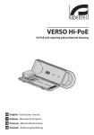
10 Disegni tecnici
I valori espressi sono in millimetri.
270
70
AREA UTILE
AREA
UTILE
A-A
466
B-B
B
70
jj
B
77
100
Fig. 16
A
15
101
113
A
26
156
VERSO
13
IT - Italiano - Manuale di istruzioni
Tettuccio in ABS
63
AREA UTILE
AREA
UTILE
A-A
400
63
210
B-B
A
94
106
B
18
B
A
15
94
135
Fig. 17
270
70
AREA UTILE
AREA
UTILE
A-A
466
B-B
A
B
156
Fig. 18
VERSO POLAR
VIDEOTEC S.p.A.
www.videotec.com
Printed in Italy
MNVCHPVB_1006_IT
A
15
101
113
B
70
VERSO COMPACT
VERSO / VERSO COMPACT /
VERSO POLAR
Caisson en polycarbonate à ouverture latérale
FR Français - Manuel d'instructions
Sommaire
FRANÇAIS
1 À propos de ce mode d’emploi..................................................................................... 5
1.1 Conventions typographiques............................................................................................................................. 5
4.1 Description et désignation du produit............................................................................................................ 6
4.2 Marquage du produit............................................................................................................................................ 6
5 Préparation du produit en vue de l’utilisation............................................................ 6
5.1 Contenu et déballage............................................................................................................................................ 6
5.2 Élimination sans danger des matériaux d’emballage................................................................................ 6
6 Installation et assemblage............................................................................................ 7
6.1 Installation................................................................................................................................................................. 7
6.1.1 Ouverture du caisson............................................................................................................................................................. 7
6.1.2 Installation de la caméra...................................................................................................................................................... 7
6.1.3 Branchement à la ligne d'alimentation........................................................................................................................... 7
6.1.3.1 Type de câble................................................................................................................................................................................................. 7
6.1.3.2 Fixation du caisson...................................................................................................................................................................................... 8
6.1.4 Installation du chauffage..................................................................................................................................................... 8
6.1.5 Installation de l’alimentateur pour caméra................................................................................................................... 9
6.1.6 Installation du ventilateur.................................................................................................................................................... 9
6.1.6.1 Alimentation 100-240Vac:.......................................................................................................................................................................10
6.1.6.2 Alimentation 12Vdc et 24Vac.................................................................................................................................................................10
6.1.7 Système de refroidissement..............................................................................................................................................10
6.1.8 Configuration pour basses températures....................................................................................................................11
7 Entretien et nettoyage................................................................................................ 11
7.1 Entretiens de la vitre et des parties en plastique (PC)..............................................................................11
8 Élimination des déchets.............................................................................................. 11
9 Données techniques.................................................................................................... 11
9.1 VERSO........................................................................................................................................................................11
9.1.1 Généralités...............................................................................................................................................................................11
9.1.2 Mécanique...............................................................................................................................................................................12
9.1.3 Électrique.................................................................................................................................................................................12
9.1.4 Environnement......................................................................................................................................................................12
9.1.5 Certifications...........................................................................................................................................................................12
9.2 VERSO COMPACT...................................................................................................................................................12
9.2.1 Généralités...............................................................................................................................................................................12
9.2.2 Mécanique...............................................................................................................................................................................12
9.2.3 Électrique.................................................................................................................................................................................12
9.2.4 Environnement......................................................................................................................................................................12
9.2.5 Certifications...........................................................................................................................................................................12
9.3 VERSO POLAR..........................................................................................................................................................13
9.3.1 Généralités...............................................................................................................................................................................13
9.3.2 Mécanique...............................................................................................................................................................................13
3
FR - Français - Manuel d'instructions
2 Notes sur le copyright et informations sur les marques de commerce..................... 5
3 Normes de securité........................................................................................................ 5
4 Identification................................................................................................................. 6
9.3.3 Électrique.................................................................................................................................................................................13
9.3.4 Environnement......................................................................................................................................................................13
9.3.5 Certifications...........................................................................................................................................................................13
FR - Français - Manuel d'instructions
10 Dessins techniques.................................................................................................... 13
4
1 À propos de ce mode
d’emploi
Avant d’installer et d’utiliser cet appareil, veuillez
lire attentivement ce mode d’emploi. Conservez-le à
portée de main pour pouvoir vous y reporter en cas
de besoin.
DANGER!
Risque élevé.
Risque de choc électrique. Sauf indication
contraire, sectionner l’alimentation avant
de procéder à toute opération.
gg
ATTENTION!
Risque moyen.
Opération extrêmement importante en vue
d’un fonctionnement correct du système;
lire avec attention les opérations indiquées
et s’y conformer rigoureusement.
hh
REMARQUE
Description des caractéristiques du
système.
Il est conseillé de procéder à une
lecture attentive pour une meilleure
compréhension des phases suivantes.
jj
2 Notes sur le copyright
et informations sur les
marques de commerce
Les noms de produit ou de sociétés cités sont des
marques de commerce ou des marques de commerce
enregistrées.
Le producteur décline toute responsabilité
pour les dommages éventuels dus à une
utilisation non appropriée des appareils
mentionnés dans ce manuel. On réserve
en outre le droit d’en modifier le contenu
sans préavis. La documentation contenue
dans ce manuel a été rassemblée et vérifiée
avec le plus grand soin, cependant, le
producteur ne peut pas s’assumer aucune
responsabilité dérivante de l’emploi de
celle là. La même chose vaut pour chaque
personne ou société impliquées dans la
création et la production de ce manuel.
hh
• L’installation et l’entretien du dispositif doivent
être exclusivement être effectués par un personnel
technique qualifié.
• Sectionner l’alimentation électrique avant toute
intervention technique sur l’appareil.
• Ne pas utiliser de câbles d’alimentation usés ou
endommagés.
• Ne procéder sous aucun prétexte à des
modifications ou des connexions non prévues
dans ce manuel: l’utilisation d’appareils non
adéquats peut comporter des dangers graves pour
la sécurité du personnel et de l’installation.
• Utiliser uniquement des pièces de rechange
d’origine. Les pièces non d’origine peuvent être
source d’incendies, de choc électrique ou autres.
• Avant de procéder à l’installation, contrôler que
le matériel fourni correspond à la commande
et examiner les étiquettes de marquage ("4.2
Marquage du produit", page 6).
• Le dispositif a été conçu pour être installé de façon
permanente à un bâtiment ou à une structure
adéquate.
• Il faut respecter les législations nationales pour
l'installation du dispositif.
• L'installation électrique du bâtiment où est placé
le dispositif doit être équipée d'un circuit de
protection (magnétothermique) bipolaire, qui doit
comprendre un interrupteur bipolaire de type
automatique qui prévoyant aussi la protection du
courant d'avarie vers la terre (magnétothermique
+ différentiel) avec distance minimale entre les
contacts de 3mm.
• Les appareils pouvant être installés à l'intérieur
du caisson doivent être conformes aux normes en
vigueur.
5
FR - Français - Manuel d'instructions
1.1 Conventions typographiques
3 Normes de securité
4 Identification
FR - Français - Manuel d'instructions
4.1 Description et désignation
du produit
Caisson moderne et novateur, étudié pour
simplifier l’installation et la maintenance, VERSO/
VERSO COMPACT assure une protection maximum
dans les environnements les plus difficiles. Son
ouverture latérale facilite l’accès et la mise en place
de la caméra, des optiques et des raccordements.
VERSO/VERSO COMPACT est entièrement fabriqué
avec un nouveau poly carbonate garantissant ainsi,
une grande résistance aux impacts, une excellente
protection aux agressions atmosphériques et aux
rayons UV. Son étanchéité est assurée grâce à des
joints en néoprène, et à presse-étoupes ou par
des passe-câbles optionnels lors de l’utilisation de
supports creux, permettant le passage protégé des
câbles.
VERSO/VERSO COMPACT permet d’utiliser différents
modes de fixation: support standard, support creux
ou installé sur une tourelle; il est compatible avec de
multiples combinaisons de caméras et objectifs.
Une version avec ventilateur pour VERSO rend
possible le bon fonctionnement des caméras IP
lorsque la température extérieure est élévée.
VERSO POLAR est équipé d’un système de chauffage
très performant qui permet le fonctionnement même
aux temperatures les plus basses.
Différents accessoires sont disponibles, tels que:
le double-toit, le chauffage standard, le chauffage
ventilé, le ventilateur, l’alimentation pour caméra
et le contact d’alarme anti-ouverture (seulement
VERSO). Des kits de montage sont inclus pour faciliter
l’ installation.
4.2 Marquage du produit
Voir l’étiquette sur l’extérieur de l’emballage.
6
5 Préparation du produit
en vue de l’utilisation
Toute modification non approuvée
expressément par le fabricant entraînera
l’annulation de la garantie.
hh
5.1 Contenu et déballage
Lors de la livraison du produit, vérifier que
l’emballage est en bon état et l’absence de tout signe
évident de chute ou d’abrasion.
En cas de dommages évidents, contacter
immédiatement le fournisseur.
Conserver l’emballage en cas de nécessité
d’expédition du produit pour réparation.
Contrôler que le contenu correspond à la liste
matériel indiquée ci-dessous:
• Caisson
• Dotation pour caisson:
• Clé Allen
• Entretoises
• Presse-étoupes
• Vis et rondelles
• Vis pour caméra
• Manuel d'instructions
5.2 Élimination sans danger
des matériaux d’emballage
Le matériel d’emballage est entièrement composé
de matériaux recyclables. Le technicien chargé de
l’installation est tenu de l’éliminer conformément aux
dispositions en matière de collecte sélective et selon
les normes en vigueur dans le pays d’utilisation.
En cas de dysfonctionnement et de retour de matériel
, il est conseillé d’utiliser l’emballage original pour le
transport.
6 Installation et
assemblage
01
03
02
L’installation et l’assemblage doivent
exclusivement être effectués par un
personnel spécialisé.
hh
Fig. 02
Avant d’effectuer toute opération, il est
indispensable de couper l'alimentation.
hh
6.1 Installation
6.1.1 Ouverture du caisson
Pour l’ouverture du caisson, dévisser les 2 vis placées
sur le côté, faire tourner le toit pare-soleil et le corps
supérieur autour de l’axe des charnières d’ouverture.
Replacer la glissière interne en fixant les vis
précédemment desserrées. Placer la camèra avec
la partie entérieure de l’optique à un centimètre du
bord supérieur du caisson pour éviter des dommages
pendant la fermeture.
Fermez le caisson apres avoir effectuè les connections
électriques.
Les conducteurs du câble d'alimentation de la caméra
doivent être fixés entre eux à proximité de la borne.
Prendre soin de garder les câbles de signal séparés de
ceux d'alimentation.
6.1.3 Branchement à la ligne
d'alimentation
Cette section décrit comment brancher la ligne
d'alimentation au caisson.
Fig. 01
On aura ainsi un accès facile à l’intérieur du caisson.
6.1.2 Installation de la caméra
Cette section décrit comment installer la caméra
à l’intérieur du caisson. Nous rappelons qu’il est
possible de prélever l’alimentation à partir du circuit
fourni, en vérifiant, au préalable, que celle-ci soit
correcte.
Ouvrez le caisson en suivant les instructions
précédentes.
Extraire la glissière interne d’appui en dévissant
partiellement les vis de fixation (01). Déplacer la
glissière en la faisant glisser jusqu’à ce que les trous
coincident avec les vis de blocage de celle-ci (02).
Fixer la caméra avec la vis de 1/4"; placer
éventuellement l’entretoise isolante entre la
caméra et la partie supérieure de la glissière (03). Si
nécessaire, utiliser les entretoises fournies pour placer
de façon correcte la caméra et l’optique.
Introduire les câbles de branchement à la ligne
d'alimentation à l'intérieur du caisson à l'aide des
presse-étoupes. Les presse-étoupes sont adaptés
à des câbles ayant un diamètre compris entre 5 et
10mm. Laisser à l'intérieur du caisson une longueur
de câble suffisante pour le branchement et serrer
opportunément les presse-étoupes.
Enlever la gaine de protection des conducteurs et les
brancher à la borne J3 (Fig. 05, page 8 et Fig. 06, page 8).
Prendre soin de laisser le conducteur de terre
plus long que les autres d'au moins 10mm. Les
conducteurs du câble d'alimentation doivent être
fixés entre eux à proximité de la borne.
Prendre soin de garder les câbles d'alimentation
séparés de ceux de signal.
6.1.3.1 Type de câble
Le type de câble à utiliser pour le branchement à
la ligne d'alimentation doit être compatible avec
l'emploi prévu. S'en tenir aux règles nationales en
vigueur concernant les installations électriques.
7
FR - Français - Manuel d'instructions
Les versions de caisson équipées de ce
dispositif peuvent exclusivement être
alimentées avec des tensions de 12Vdc ou
24Vac.
hh
6.1.3.2 Fixation du caisson
Le caisson doit être fixé par des moyens adéquats à
l'aide d'étriers ou de supports. Les moyens de fixation
doivent garantir l'étanchéité mécanique et appliquer
une force égale au moins à quatre fois le poids total
de l’appareil.
Insérer le connecteur à 2 pôles placé en bout de câble
dans son emplacement sur le circuit d’appui, indiqué
par J2 HEATER (Fig. 05, page 8 et Fig. 06, page 8).
J2 - Chauffage
J6 - Ventilateur
FR - Français - Manuel d'instructions
6.1.4 Installation du chauffage
Cette section décrit comment installer l’option
chauffage dans les caissons du type anti-poussières
qui n’en sont pas équipés. Le chauffage peut être
fourni avec des tensions de travail de 12Vdc/24Vac
ou 115/230Vac et comprend, selon la tension
d’utilisation, la résistance de chauffage précâblée,
les dissipateurs métalliques et les vis pour la fixation
du kit.
J4 - OUT
Fig. 05
J3 - IN J1 - Camera
OUT
J5 - Alimentation
VERSO.
Ouvrir le caisson selon les instructions décrites
précédemment. Fixer le kit de chauffage aux points
prédisposées sur le corps du caisson.
J2 - Chauffage
J5 - Alimentation
La résistance précâblée doit être placée entre les
2 dissipateurs avant la fixation pour en garantir le
contact et assurer de cette façon une bonne diffusion
de la chaleur.
J4 - OUT
Fig. 06
J3 - IN
J1 - Camera
OUT
J6 - Ventilateur
VERSO COMPACT.
Replacer la glissière d’appui interne et fermer le
caisson.
Dans le circuit, il est aussi possible de
prélever l’alimentation pour une caméra. En
alimentant le circuit à partir d’une source
externe, il faut faire attention au type
de tension utilisée et adopter, selon les
exigences, le kit d’alimentation correct.
hh
Fig. 03
Passer le fil du chauffage dans les emplacements
prédisposés.
Fig. 04
8
6.1.5 Installation de l’alimentateur
pour caméra
En alimentant le circuit à partir d’une
source externe, il faut faire attention
au type de tension utilisée et, selon les
exigences, au bon kit d’alimentation.
Pour monter l’option alimentateur, il n’est
nécessaire d’enlever aucun composant déjà
installé.
hh
Non applicable pour les caissons équipés de
système pour le refroidissement installé.
hh
Fig. 07
Fig. 08
IN 100-240Vac - OUT 12Vdc.
IN 230Vac - OUT 24Vac.
Ouvrir le caisson en suivant les instructions décrites
précédemment
Placer l’alimentateur dans l’emplacement prévu à cet
effet (Fig. 04, page 8) face aux nervures de soutien.
6.1.6 Installation du ventilateur
Non applicable pour les caissons équipés de
système pour le refroidissement installé.
hh
En face de la boîte de connexions indiquée
par J4, il est possible de prélever la tension
d’alimentation principale dérivant d’une
source externe. En alimentant le circuit à
partir d’une source externe, il faut faire
attention au type de tension utilisée et,
selon les exigences, au kit d’alimentation
correct.
hh
Le ventilateur doit être monté d’après
les instructions pour garantir une bonne
circulation de l’air à l’intérieur du caisson.
hh
Cette section décrit comment installer l’option
ventilateur dans les caissons qui n’en sont pas
équipés. Le kit de ventilation peut être fourni
de 3 configurations différentes selon la tension
d’alimentation disponible.
Ouvrir le caisson en suivant les instructions décrites
précédemment.
Fixer le ventilateur, à l’aide du petit étrier de support
en angle, à l’intérieur du corps du caisson en utilisant
les vis fournies prévues. Une regolation est possible
pour la version en 420mm (01) et 2 pour celle en
360mm (02).
01
Fig. 09
02
Fixer l’alimentateur au corps du cais-son en utilisant
le petit étrier en angle prévu à cet effet et les vis
fournies dans le kit d’alimentation.
Insérer le connecteur à 6 pôles placé en bout de câble
dans l’emplacement indiqué par J5, sur le circuit
d’appui (Fig. 05, page 8 et Fig. 06, page 8).
Fermer le caisson.
Fig. 10
Insérer le connecteur à 2 pôles placé en bout de câble
dans l’emplacement indiqué par J6 (FAN) sur le circuit
d’appui (Fig. 05, page 8 et Fig. 06, page 8).
9
FR - Français - Manuel d'instructions
Cette section décrit comment installer l’option
alimentateur à l’intérieur du caisson. Les
alimentateurs qui peuvent être installés sont de 2
catégories selon les exigences. Un modèle peut avoir
une tension d’entrée allant de 100-240Vac avec une
tension en sortie égale à 12Vdc, 1A. L’autre possibilité
prévoit un alimentateur de type différent qui peut
avoir une tension d’entrée de 115/230Vac avec une
tension en sortie égale à 24Vac, 400mA.
6.1.6.1 Alimentation 100-240Vac:
Installer l’alimentateur fourni avec le kit de ventilation
comme cela est décrit dans chapitre "6.1.5 Installation
de l’alimentateur pour caméra", page 9.
Pour garantir un degré de protection IP44, installer
le caisson au support en respectant les limites
d'inclinaison selon la figure.
Fermer le caisson.
45°
0˚
Dans ce cas, un connecteur muni des branchements
nécessaires est fourni avec le kit de ventilation
pour rendre le circuit d’appui compatible au
fonctionnement avec la tension d’alimentation
présente. Ce connecteur doit être inséré dans
l’emplacement indiqué par J5, sur le circuit fourni.
45°
FR - Français - Manuel d'instructions
6.1.6.2 Alimentation 12Vdc et 24Vac
Fermer le caisson.
6.1.7 Système de refroidissement
Cette section décrit le mode de connexion des
caissons équipés d’un système de refroidissement.
Pour ces versions, aucun composant ne doit être
installé à l’intérieur, ces dernières étant fournies avec
tout le nécessaire en fonction du modèle requis.
Il est important contrôler la disposition des ailettes
du filtre d’entrée d’air lors de l’installation.
Fig. 12
Rotation maxi sur l’axe transversal: 0˚.
Inclination maxi sul l’axe longitudinal: +/- 45˚.
Ouvrir le caisson comme indiqué dans les instructions
précédentes.
Effectuer les connexions électriques pour le
fonctionnement du système de refroidissement sur la
borne indiquée comme J8 FAN.
J3 - Chauffage
J7 - Alimentation
IN
OUT
Fig. 11
L’orientation des ailettes en fonction de l’angle
d’inclinaison du caisson doit empêcher toute entrée
d’eau en cas de pluie.
J5 - Camera
OUT
J1 - IN
J2 - OUT
J8 - Ventilateur
Fig. 13
Le circuit offre la possibilité de prélever l’alimentation
pour une caméra sur la borne indiquée comme J2.
Il est également possible de prélever l’alimentation
nécessaire au système de chauffage en option, borne
indiquée comme J3 HEATER ("6.1.4 Installation du
chauffage", page 8).
Fermer le caisson en procédant selon les indications
précédentes mais en sens contraire.
En cas d’alimentation du circuit au moyen
d’une source externe, attention au type
de tension utilisée. Les versions de
caisson équipées de ce dispositif peuvent
exclusivement être alimentées avec des
tensions de 12Vdc ou 24Vac.
hh
10
6.1.8 Configuration pour basses
températures
Outre le caisson standard, une version à triple
chauffage est prévue pour un fonctionnement à
basses températures.
7 Entretien et nettoyage
7.1 Entretiens de la vitre et des
parties en plastique (PC)
On doit éviter alcool éthylique, solvants,
hydrocarbures hydro-génés, acides forts
et alcali. L’emploi de ce type de produits
abîme d’une façon irréparable la surface
traitée.
hh
8 Élimination des déchets
Fig. 14
La version à triple chauffage est fournie entièrement
câblée par le fabricant. Le circuit du caisson est
représenté dans la figure.
J6 - Camera OUT
24Vac/12Vdc
J1-J2-J3 - Chauffage
J8 - Alimentation
Ce symbole et le système de recyclage ne
sont appliqués que dans les pays UE et non
dans les autres pays du monde.
nn
Votre produit est conçu et fabriqué avec des matèriels
et des composants de qualité supérieure qui peuvent
être recyclés et réutilisés.
Ce symbole signifie que les équipements électriques
et électroniques en fin de vie doivent être éliminés
séparément des ordures ménagères.
Nous vous prions donc de confier cet équipement à
votre Centre local de collecte ou Recyclage.
J10 - OUT
230Vac/24Vac
Fig. 15
J7 - IN
230Vac/24Vac
Dans l’Union Européenne, il existe des systèmes
sélectifs de collecte pour les produits électriques et
électroniques usagés.
9 Données techniques
9.1 VERSO
9.1.1 Généralités
Construction en technopolymère de haute résistance
(polycarbonate)
Toit pare-soleil en ABS
Couleur RAL9002
Visserie extérieure en acier Inox
Livré avec manuel d’instructions, sachet déshydratant,
accessoires destinés au montage de la caméra et de
l’objectif
11
FR - Français - Manuel d'instructions
Nous conseillons l’emploi, avec un chiffon souple,
de savons neutres dilués avec de l’eau ou bien de
produits spécifiques pour le nettoyage des vitres de
lunettes.
9.1.2 Mécanique
3 presse-étoupes M16
Fenêtre en polycarbonate (WxH): 105x64mm
Surface intérieure utile (WxH): 70x70mm
Longueur utile du caisson avec accessoires: 270mm
Poids net: 1.5kg
FR - Français - Manuel d'instructions
9.1.3 Électrique
Chauffage Ton 15°C±3°C Toff 22°C±3°C
-- IN 12Vdc/24Vac, consommation 20W max
-- IN 115/230Vac, consommation 40W max
Ventilateur à cycle continu pour assistance chauffage
9.2 VERSO COMPACT
9.2.1 Généralités
Construction en technopolymère de haute résistance
(polycarbonate)
Toit pare-soleil en ABS
Couleur RAL9002
Visserie extérieure en acier Inox
Caisson fourni avec manuel d’instructions, sachet
déshydratant, accessoires pour le montage de la caméra
et objectif
9.2.2 Mécanique
-- IN 12Vdc, consommation 4W max
2 presse-étoupes M16
-- IN 24Vac, consommation 4W max
Fenêtre en polycarbonate (WxH): 98x55mm
-- IN 100-240Vac, consommation 4W max, avec
alimentation wide range IN 100-240Vac/12Vdc
Surface intérieure utile (WxH): 63x63mm
Ventilateur avec filtre d’air et thermostat, Ton 35°C±3°C
Toff 20°C±3°C, avec alimentation wide range IN 100240Vac - OUT 12Vdc
-- IN 110-240Vac, consommation 4W max
Ventilateur avec thermostat Ton 35°C±3°C Toff
20°C±3°C pour les modèles avec double filtre pour le
renouvellement de l’air
-- IN 12Vdc, consommation 4W max
-- IN 24Vac, consommation 4W max
Alimentation pour camèra
-- IN 100-240Vac - OUT 12Vdc, 50/60 Hz, 1A
-- IN 230Vac - OUT 24Vac, 50/60Hz, 400mA
9.1.4 Environnement
Intérieur / Extérieur
Température d’exercice avec chauffage: -20°C / +60°C
Longueur utile intérieure avec ou sans accessoires:
210mm
Poids net: 1.1kg
9.2.3 Électrique
Chauffage Ton 15°C±3°C Toff 22°C±3°C
-- IN 12Vdc/24Vac, consommation 20W max
-- IN 115/230Vac, consommation 40W max
Ventilateur à cycle continu pour assistance chauffage
-- IN 12Vdc, consommation 4W max
-- IN 24Vac, consommation 4W max
-- IN 100-240Vac, consommation 4W max (avec
alimentation wide range IN 100-240Vac/12Vdc)
Alimentation pour caméra
-- IN 100-240Vac - OUT 12Vdc, 50/60 Hz, 1A
-- IN 230Vac - OUT 24Vac, 50 Hz, 400mA
Très bonne résistance aux agents chimiques suivants:
bases, alcools, gaz, hydrocarbures
9.2.4 Environnement
Bonne résistance: acides organiques et inorganiques,
huiles
Température d’exercice avec chauffage: -20°C / +60°C
Basse résistance: solvants
9.1.5 Certifications
CE EN61000-6-3, EN60950-1, EN50130-4
Intérieur / Extérieur
Trés bonne résistance aux agents chimiques suivants:
bases, alcools, gaz, hydrocarbures
Bonne résistance: acides organiques et inorganiques,
huiles
IP66/IP67 EN60529 avec presse-étoupes
Basse résistance: solvants
IP66/IP67 EN60529 avec bagues d’étanchéité et support
avec passage interne des câbles
9.2.5 Certifications
IP55 EN60529 avec support avec passage interne des
câbles
IP66/IP67 EN60529 avec presse-étoupes
IP44 EN60529 pour les modèles avec ventilateur et
double filtre
CE EN61000-6-3, EN60950-1, EN50130-4
IP66/IP67 EN60529 avec passe-câbles étanches et
passage protégé des câbles
Auto-extinction V1 UL94
IP55 EN60529 avec support avec passage interne des
câbles
Résistance aux impacts IK10 EN62262
Auto-extintion V1 UL94
Résistance aux impacts IK10 EN62262
12
9.3 VERSO POLAR
9.3.4 Environnement
Intérieur / Extérieur
9.3.1 Généralités
Température d’exercice avec chauffage: -55°C / +60°C
Construction en technopolymère de haute résistance
(polycarbonate)
Très bonne résistance aux agents chimiques suivants:
bases, alcools, gaz, hydrocarbures
Toit pare-soleil en ABS
Bonne résistance: acides organiques et inorganiques,
huiles
Visserie extérieure en acier Inox
Basse résistance: solvants
Livré avec manuel d’instructions, sachet déshydratant,
accessoires destinés au montage de la caméra et de
l’objectif
9.3.5 Certifications
9.3.2 Mécanique
IP66/IP67 EN60529 avec presse-étoupes
CE EN61000-6-3, EN60950-1, EN50130-4
IP66/IP67 EN60529 avec bagues d’étanchéité et support
avec passage interne des câbles
3 presse-étoupes M16 en laiton nickelé
Fenêtre en polycarbonate (WxH): 105x64mm
Surface intérieure utile (WxH): 70x70mm
IP55 EN60529 avec support avec passage interne des
câbles
Longueur utile du caisson avec accessoires: 270mm
Auto-extinction V1 UL94
Poids net: 1.5kg
Résistance aux impacts IK10 EN62262
9.3.3 Électrique
Chauffage Ton 15°C±3°C Toff 22°C±3°C
-- IN 12Vdc/24Vac, consommation 60W max
-- IN 115/230Vac, consommation 120W max
Alimentation pour camèra
-- IN 100-240Vac - OUT 12Vdc, 50/60 Hz, 1A
-- IN 230Vac - OUT 24Vac, 50/60Hz, 400mA
10 Dessins techniques
Les valeurs sont entendues en millimètres.
270
70
SURFACE UTILE
SURFACE
UTILE
A-A
466
70
jj
B-B
B
B
77
100
Fig. 16
A
15
101
113
A
26
156
VERSO
13
FR - Français - Manuel d'instructions
Couleur RAL9002
63
SURFACE UTILE
SURFACE
UTILE
A-A
400
63
210
B-B
A
94
106
B
18
B
A
15
94
135
Fig. 17
270
70
SURFACE UTILE
SURFACE
UTILE
A-A
466
70
VERSO COMPACT
B-B
A
B
156
Fig. 18
VERSO POLAR
VIDEOTEC S.p.A.
www.videotec.com
Printed in Italy
MNVCHPVB_1006_FR
A
15
101
113
B
VERSO / VERSO COMPACT /
VERSO POLAR
Polykarbonat- Gehäuse mit Seitenöffnung
DE Deutsch - Bedienungslanleitung
Inhaltsverzeichnis
DEUTSCH
1 Allgemeines................................................................................................................... 5
1.1 Schreibweisen.......................................................................................................................................................... 5
2 Anmerkungen zum Copyright und Informationen zu den Handelsmarken............. 5
3 Sicherheitsnormen........................................................................................................ 5
4 Identifizierung............................................................................................................... 6
5 Vorbereitung des Produktes auf den Gebrauch......................................................... 6
5.1 Inhalt und Entfernen der Verpackung............................................................................................................. 6
5.2 Sichere Entsorgung der Verpackungsmaterialien....................................................................................... 6
6 Installation und Zusammenbau................................................................................... 7
6.1 Installation................................................................................................................................................................. 7
6.1.1 Öffnung des Schutzgehäuses............................................................................................................................................. 7
6.1.2 Installation der Kamera......................................................................................................................................................... 7
6.1.3 Anschluss an die Versorgungsleitung.............................................................................................................................. 7
6.1.3.1 Kabelart............................................................................................................................................................................................................ 7
6.1.3.2 Befestigung des Gehäuses........................................................................................................................................................................ 8
6.1.4 Installation der Heizung....................................................................................................................................................... 8
6.1.5 Installation des Netzteil für Kamera................................................................................................................................. 9
6.1.6 Installation des Lüfters.......................................................................................................................................................... 9
6.1.6.1 Betriebsspannung 100-240Vac.............................................................................................................................................................10
6.1.6.2 Betriebsspannung 12Vdc oder 24Vac.................................................................................................................................................10
6.1.7 Kühlungsystem......................................................................................................................................................................10
6.1.8 Niedertemperaturausführung..........................................................................................................................................11
7 Wartung und Reinigung.............................................................................................. 11
7.1 Reinigung des Glases und der Kunststoffteile (PC)...................................................................................11
8 Müllentsorgungsstellen.............................................................................................. 11
9 Technische Daten......................................................................................................... 11
9.1 VERSO........................................................................................................................................................................11
9.1.1 Allgemeines............................................................................................................................................................................11
9.1.2 Mechanik..................................................................................................................................................................................12
9.1.3 Elektrik.......................................................................................................................................................................................12
9.1.4 Umgebung..............................................................................................................................................................................12
9.1.5 Zertifizierungen.....................................................................................................................................................................12
9.2 VERSO COMPACT...................................................................................................................................................12
9.2.1 Allgemeines............................................................................................................................................................................12
9.2.2 Mechanik..................................................................................................................................................................................12
9.2.3 Elektrik.......................................................................................................................................................................................12
9.2.4 Umgebung..............................................................................................................................................................................12
9.2.5 Zertifizierungen.....................................................................................................................................................................12
9.3 VERSO POLAR..........................................................................................................................................................13
9.3.1 Allgemeines............................................................................................................................................................................13
9.3.2 Mechanik..................................................................................................................................................................................13
3
DE - Deutsch - Bedienungslanleitung
4.1 Beschreibung und Bezeichnung des Produktes.......................................................................................... 6
4.2 Kennzeichnung des Produkts............................................................................................................................. 6
9.3.3 Elektrik.......................................................................................................................................................................................13
9.3.4 Umgebung..............................................................................................................................................................................13
9.3.5 Zertifizierungen.....................................................................................................................................................................13
DE - Deutsch - Bedienungslanleitung
10 Technische Zeichnungen.......................................................................................... 13
4
1 Allgemeines
3 Sicherheitsnormen
Lesen Sie bitte vor dem Installieren und dem
Verwenden dieses Gerätes die Bedienungsanleitung
sorgfältig durch. Bewahren Sie sie zum späteren
Nachschlagen auf.
hh
1.1 Schreibweisen
ACHTUNG!
Mittlere Gefährdung.
Der genannte Vorgang hat große
Bedeutung für den einwandfreien Betrieb
des Systems: es wird gebeten, sich die
Verfahrensweise anzulesen und zu
befolgen.
hh
ANMERKUNG
Beschreibung der Systemmerkmale.
Eine sorgfältige Lektüre wird empfohlen,
um das Verständnis der folgenden Phasen
zu gewährleisten.
jj
2 Anmerkungen
zum Copyright und
Informationen zu den
Handelsmarken
Die angeführten Produkt- oder Firmennamen sind
Handelsmarken oder eingetragene Handelsmarken.
• Die Installation und Wartung der Vorrichtung ist
technischen Fachleuten vorbehalten.
• Vor technischen Eingriffen am Gerät muss die
Stromversorgung unterbrochen werden.
• Es dürfen keine Versorgungskabel mit Verschleißoder Alterungsspuren verwendet werden.
• Unter keinen Umständen dürfen Veränderungen
oder Anschlüsse vorgenommen werden, die
in diesem Handbuch nicht genannt sind: Der
Gebrauch ungeeigneten Geräts kann die Sicherheit
des Personals und der Anlage schwer gefährden.
• Es dürfen nur Original-Ersatzteile verwendet
werden. Nicht originale Ersatzteile können zu
Bränden, elektrischen Entladungen oder anderen
Gefahren führen.
• Vor der Installation ist anhand des
Kennzeichnungsschildes nachzuprüfen, ob das
gelieferte Material die gewünschten Eigenschaften
aufweist ("4.2 Kennzeichnung des Produkts", Seite 6).
• Die Einrichtung ist für die dauerhafte Installation
an ein Gebäude oder eine geeignete Struktur
konzipiert.
• Die nationalen Vorschriften für die Installation der
Einrichtung sind einzuhalten.
• Die elektrische Anlage des Gebäudes, an
dem die Einrichtung installiert wird, muss
mit einem zweipoligen Schutzstromkreis
(elektromagnetische und thermische
Überstromauslösung) versehen sein. Dieser muss
einen zweipoligen Leistungsschalter umfassen,
der mit einem Kontaktabstand von mindestens
3mm auch den Schutz des Erdschlussstroms
vorsieht (elektrischmagnetische und thermische
Überstromauslösung + Differenzial).
• Die in das Gehäuse installierten Geräte müssen
den geltenden Normen genügen.
5
DE - Deutsch - Bedienungslanleitung
GEFAHR!
Erhöhte Gefährdung.
Stromschlaggefahr. Falls nichts anderes
angegeben, unterbrechen Sie die
Stromversorgung, bevor die beschriebenen
Arbeiten durchgeführt werden.
gg
Der Hersteller lehnt jede Haftung für
eventuelle Schäden ab, die aufgrund
unsachgemäßer Anwendung der in diesem
Handbuch erwähnten Geräte entstanden
ist. Ferner behält er sich das Recht vor, den
Inhalt ohne Vorkündigung abzuändern.
Die Dokumentation in diesem Handbuch
wurde sorgfältig ausgeführt und überprüft,
dennoch kann der Hersteller keine Haftung
für die Verwendung übernehmen. Dasselbe
gilt für jede Person oder Gesellschaft, die
bei der Schaffung oder Produktion von
diesem Handbuch miteinbezogen ist.
4 Identifizierung
4.1 Beschreibung und
Bezeichnung des Produktes
DE - Deutsch - Bedienungslanleitung
Als modernes und innovatives Gehäuse, das zur
Vereinfachung von Installation und Service konzipiert
wurde, bietet VERSO/VERSO COMPACT totalen
Wetterschutz. Seine Seitenöffnung erleichtert
erheblich den Zugriff auf die Kamera, die Optiken
und sämtliche Anschlüsse.
Vollständig aus dem neuesten und
widerstandsfähigstes Technopolymer hergestellt, ist
VERSO/VERSO COMPACT sehr schlagfest und bietet
einen wirksamen Schutz gegen Witterungseinflüsse
und UV-Strahlungen. Seine Dichtheit wird von den
Neopren-Dichtungen und den Kabelshellen oder von
den wahlfreien Gummidichtungsringe (mit Halterung
mit innerer Kabelführung) garantiert.
VERSO/VERSO COMPACT bietet mit der
Wandhalterung, der Halterung mit innerer
Kabelführung und dem Schwenk-Neige-Kopf
mehrere Montagevarianten. Zudem ist das Gehäuse
in der Lage, die meisten Kombinationen aus Kameras
und Optiken aufzunehmen.
Das VERSO Gehäuse ist auch in der Version mit einem
sehr effizienten Luftrad verfügbar für Anwendungen
mit IP Kamera und für hohe Temperaturen.
VERSO POLAR ist mit einem hochleistenden
Heizungssystem mitgeliefert, das die Verwendung
auch in strengsten Temperaturen ermöglicht.
Erhältlich ist ein umfangreiches Zubehörprogramm
mit Sonnenschutzdach, Heizung, Lüfter,
Kameranetzteil und Alarmkontakt (nur für VERSO)
zum Schutz gegen Öffnung. Die Zubehörartikel
werden als einfach zu installierender Bausatz
geliefert.
4.2 Kennzeichnung des
Produkts
Siehe das Schild außen auf der Verpackung.
6
5 Vorbereitung des
Produktes auf den
Gebrauch
Jede vom Hersteller nicht ausdrücklich
genehmigte Veränderung führt zum Verfall
der Gewährleistungsrechte.
hh
5.1 Inhalt und Entfernen der
Verpackung
Bei der Lieferung des Produktes ist zu prüfen, ob die
Verpackung intakt ist oder offensichtliche Anzeichen
von Stürzen oder Abrieb aufweist.
Bei offensichtlichen Schadensspuren an der
Verpackung muss umgehend der Lieferant
verständigt werden.
Bewahren Sie die Verpackung auf für den Fall, dass
das Produkt zur Reparatur eingesendet werden muss.
Prüfen Sie, ob der Inhalt mit der nachstehenden
Materialliste übereinstimmt:
• Gehäuse
• Lieferumfang für Gehäuses:
• Innensechskantschlüssel
• Abstandsstücke
• Kabelschellen
• Schrauben und Scheiben
• Schrauben für Kamera
• Bedienungslanleitungen
5.2 Sichere Entsorgung der
Verpackungsmaterialien
Die Verpackungsmaterialien sind vollständig
wiederverwertbar. Es ist Sache des
Installationstechnikers, sie getrennt, auf jeden
Fall aber nach den geltenden Vorschriften des
Anwendungslandes zu entsorgen.
Es wird nochmals empfohlen, mit Fehlfunktionen
behaftetes Material in der Originalverpackung
zurückzusenden.
6 Installation und
Zusammenbau
01
03
02
Installation und Zusammenbau sind
Fachleuten vorbehalten.
hh
Die mit dieser Einrichtung ausgestatteten
Gehäuse-versionen können nur mit
Spannungswerten von 12Vdc oder 24Vac
versorgt werden.
hh
6.1 Installation
6.1.1 Öffnung des Schutzgehäuses
Zur Öffnung des Gehäuses die beiden an der
Flanke befindlichen Schrauben abdrehen, nun die
Haube und den oberen Korpus um die Achse der
Öffnungsscharniere drehen.
DE - Deutsch - Bedienungslanleitung
Vor allen Eingriffen immer den Netzstecker
aus der Steckdose ziehen.
hh
Fig. 02
Bringen Sie nun den internen Schlitten wieder
an seine Position und fixieren ihn mit den vorher
gelockerten Schrauben. Das Gehäuse muß mit
dem Vorderteil der Optik im Abstand von einem
Zentimeter von der oberen Gehäuseleiste stellen
werden, um Schaden während des Schlissens zu
vermeiden.
Schließen Sie das Gehäuse nach Überprüfung der
jeweilige elektrischen Anschlüsse.
Die Leiter des Kabels für die Versorgung der Kamera
müssen in Klemmennähe fest miteinander verbunden
werden. Achten Sie darauf, die Signalkabel von den
Versorgungskabeln getrennt zu halten.
6.1.3 Anschluss an die
Versorgungsleitung
Fig. 01
Auf diese Weise gelangt man leicht ans
Gehäuseinnere.
6.1.2 Installation der Kamera
In diesem Abschnitt wird erläutert, wie die Kamera
in das Gehäuseinnere eingebaut wird. Denken
Sie daran, daß die Stromversorgung aus der
beiliegenden Schaltung bezogen werden kann, falls,
wie vorher zu prüfen ist, die Werte übereinstimmen.
Das Schutzgehäuse wie frueher beschrieben öffnen.
Den internen Auflageschlitten herausziehen, indem
man die Befestigungsschrauben teilweise löst
(01). Nun den Schlitten soweit gleiten lassen, bis
seine Bohrungen mit den Befestigungsschrauben
übereinstimmen (02).
Befestigen Sie die Kamera mit der 1/4"-Schraube;
bei Bedarf kann das Isolierstück zwischen Kamera
und oberen Schlittenteil gelegt werden (03). Falls
erforderlich, kann die Kamera samt Optik mit Hilfe
der bei liegenden Paßstücke ausgerichtet werden.
Dieser Abschnitt beschreibt, wie die
Versorgungsleitung an das Gehäuse angeschlossen
wird.
Die Kabel für den Anschluss an die Versorgungsleitung
durch die Kabelschellen ins Gehäuseinnere führen.
Die Kabelschellen sind für Kabeldurchmesser von 5
bis 10mm geeignet. Belassen Sie im Gehäuse eine
Kabellänge, die für den Anschluss ausreicht und sichern
Sie die Kabelschellen.
Die Schutzummantelung der Leiter entfernen und die
Leiter an die Klemme J3 anschließen (Fig. 05, Seite 8
und Fig. 06, Seite 8).
Achten Sie darauf, dass der Erdleiter mindestens
10 mm länger gelassen wird als die anderen
Kabel. Die Leiter des Versorgungskabels müssen in
Klemmennähe fest miteinander verbunden werden.
Achten Sie darauf, dass die Versorgungskabel von
den Signalkabeln getrennt gehalten werden.
6.1.3.1 Kabelart
Die für den Anschluss an die Versorgungsleitung
benutzte Kabelart muss für den vorgesehenen
Gebrauch geeignet sein. Beachten Sie die
geltenden nationalen Vorschriften bezüglich
Elektroinstallationen.
7
6.1.3.2 Befestigung des Gehäuses
Das Gehäuse muss mit geeigneten Mitteln über
Bügel oder Halterungen befestigt werden. Die
Befestigungsmittel müssen die mechanische
Festigkeit beim Anlegen von mindestens dem
vierfachen Gesamtgewicht des Gerätes garantieren.
Setzen Sie den 2- poligen Stecker am Kabelende an
die vorgesehene Stelle der Trägerschaltung, gekennzeichnet durch die Aufschrift J2, HEATER (Fig. 05, Seite
8 und Fig. 06, Seite 8).
J2 - Heizung
J6 - Lüfter
DE - Deutsch - Bedienungslanleitung
6.1.4 Installation der Heizung
In diesem Abschnitt wird die Heizungsinstal-lation in
jene Staubschutzgehäuse behandelt, die noch nicht
darüber verfügen. Die Heizung ist lieferbar mit den
Betriebsspannungen 12Vdc/24Vac oder 115/230Vac
und enthält den zur jeweiligen Versorgungsspannung
passenden, bereits verkabelten Heizwiderstand, die
Metallableiter und die Fixierschrauben.
Öffnen Sie, wie oben beschrieben, das Gehäuse.
Reichen Sie den Heizungsdraht durch die
vorgesehenen Halterungen.
J4 - OUT
Fig. 05
J3 - IN J1 - Camera
OUT
J5 - Netzteil
VERSO.
J2 - Heizung
J5 - Netzteil
Der vorverkabelte Heizwiderstand muß, bevor er
befestigt wird, zwischen die beiden Ableiter gesetzt
werden (04), damit der Kontakt gewährleistet ist und
die Wärme richtig verteilt wird.
J4 - OUT
Fig. 06
J3 - IN
J1 - Camera
OUT
J6 - Lüfter
VERSO COMPACT.
Jetzt den internen Auflageschlitten wieder
positionieren und das Gehäuse schließen.
Fig. 03
Befestigen Sie das Heizungs-Kit an den vorgesehenen
Stellen des Gehäusekörpers.
Fig. 04
8
Die Schaltung bietet daneben die
Möglichkeit, die Stromversorgung für
eine Kamera abzugreifen. Speist man den
Schaltkreis aus einer externen Quelle, ist
darauf zu achten, welcher Spannungstyp
benutzt wird. Verwenden Sie das Kit
mit dem für den Einzelfall geeigneten
Netzversorgungsgerät.
hh
6.1.5 Installation des Netzteil für
Kamera
Wenn der Schaltkreis von einer externen
Energiequelle gespeist wird, muß auf die
Versorgungsspannung geachtet werden.
Verwenden Sie das für den Einzelfall
geeignete Netzgerät. Für den Einbau des
Zusatzspeisers braucht keine vorinstallierte
Kom-ponente entfernt zu werden.
hh
Nicht anwendbar in Gehäusen mit
installiertem Kühlsystem
hh
Fig. 07
6.1.6 Installation des Lüfters
Nicht anwendbar in Gehäusen mit
installiertem Kühlsystem
hh
DE - Deutsch - Bedienungslanleitung
Dieser Abschnitt befaßt sich mit der Installation
des Zusatzspeisegerätes im Innern des Gehäuses.
Es lassen sich je nach Bedarf 2 Kategorien von
Netzadaptern installieren. Ein Modell hat eine
Eingangsspannung von 100-240Vac bei einer
Ausgangsspannung von 12Vdc, 1A. Die Alternative
ist ein anderer Typ des Netzteils mit einer
Eingangsspannung von 115/230Vac bei einer
Ausgangsspannung von 24Vac, 400mA.
An der mit J4 gekennzeichneten
Klemmleiste läßt sich die von einer
externen Quelle stammende HauptVersorgungsspannung abgreifen.
Wird die Schaltung von einer externen
Quelle gespeist, ist darauf zu achten,
ob die richtige Spannung benutzt wird.
Verwenden Sie den auf den Einzelfall
abgestimmten Netzadapter.
hh
IN 100-240Vac - OUT 12Vdc.
Der Lüfter ist nach der Anleitung
einzubauen (Fig. 05), damit die Luft im
Gehäuse-innern richtig zirkulieren kann.
hh
Fig. 08
IN 230Vac - OUT 24Vac.
Öffnen Sie das Gehäuse so, wie es vorstehend
beschrieben wird.
Bringen Sie das Netzteil an der vorgesehenen
Stelle unter (Fig. 04, Seite 8), und zwar in Höhe der
Verstärkungs-rippen.
Dieser Abschnitt befaßt sich mit der Installation
des Zusatzlüfters in Gehäuse ohne Belüftung.
Der Belüftungsbausatz ist in drei verschiedenen
Konfigurationen erhältlich, je nach verfügbarer
Versorgungsspan-nung.
Öffnen Sie das Gehäuse, wie vorstehend beschrieben.
Fixieren Sie den Lüfter mit einer winkelförmigen
Bügelhalterung im Innern des Gehäusekorpus mit
den beiliegenden Schrauben. Moglich sind eine
Stellung für die 420mm-Version (01) und 2 für die
360mm-Version (02).
01
02
Fig. 09
Befestigen Sie das Netzgerät mit dem geeigneten
Winkeleisen und den bei liegenden Schrauben am
Gehäuse -korpus.
Fig. 10
Setzen Sie den 6-poligen Stecker am Kabelende an
die vorgesehene Stelle des Auflageschaltkreises,
gekennzeichnet durch die Aufschrift J5 (Fig. 05, Seite 8
und Fig. 06, Seite 8).
Fügen Sie den 2- poligen Stecker am Kabelende in
die vorgesehene, mit J6 (FAN) gekennzeichnete Stelle
des Auflageschaltkreises ein (Fig. 05, Seite 8 und Fig.
06, Seite 8).
Das Gehäuse schließen.
9
6.1.6.1 Betriebsspannung 100-240Vac
Installieren Sie das mit dem Belüftungs- Kit gelieferte
Netzteil, wie im Kapitel "6.1.5 Installation des Netzteil
für Kamera", Seite 9.
Das Gehäuse auf der Halterung gemäß den
Neigungsbegrenzungen des Bildes installieren, um
den IP44- Schutzgrad zu garantieren.
Das Schutzgehäuse schließen.
45°
0˚
In diesem Fall wird gemeinsam mit dem BelüftungsKit ein Stecker mit geeigneten Anschlüssen geliefert,
um den Auflageschaltkreis mit dem Betrieb der
vorhandenen Versorgungsspannung kompatibel zu
machen. Dieser Stecker muß an der vorgesehenen,
mit J5 bezeichneten Stelle auf dem beiliegenden
Schaltkreis eingefügt werden.
45°
DE - Deutsch - Bedienungslanleitung
6.1.6.2 Betriebsspannung 12Vdc oder
24Vac
Das Schutzgehäuse schließen.
6.1.7 Kühlungsystem
Dieser Abschnitt erläutert, wie die Gehäuse mit
Kühlanlage angeschlossen werden.
Bei diesen Ausführungen braucht keine Komponente
im Innern untergebracht zu werden, weil sie bereits
je nach gewünschtem Modell komplett mit allen
erforderlichen Teilen geliefert werden.
Fig. 12
Maximale Drehung auf der Querachse: 0˚.
Maximale Neigung auf der Längsachse: +/- 45˚.
Das Gehäuse öffnen, wie vorstehend beschrieben.
Die elektrischen Anschlüsse für den Betrieb der
Kühlanlage an der Klemme J8 FAN vornehmen.
J3 - Heizung
Es ist wichtig, bei der Installation auf die
Rippenanordnung des Lufteintrittsfilters zu achten.
IN
J7 - Netzteil
J5 - Camera
OUT
J1 - IN
J2 - OUT
J8 - Lüfter
Fig. 13
OUT
Fig. 11
Die Rippen sind in Abhängigkeit vom
Neigungswinkel des Gehäuses so auszurichten, daß
bei Regen kein Wasser eintritt.
Im Schaltkreis besteht die Möglichkeit, die
Speisung für eine Videokamera an der Klemme
mit der Bezeichnung J2 abzugreifen. Man kann
auch die Speisung für die als Extra erhältliche
Beheizungsanlage abgreifen, die Klemme ist mit
J3 HEATER gekennzeichnet ("6.1.4 Installation der
Heizung", Seite 8).
Das Gehäuse wird in der umgekehrten Reihenfolge
wie der vorstehend beschriebenen geschlossen.
m Wenn der Stromkreis von einer externen
Quelle gespeist wird, muß auf die benutzte
Spannungsart geachtet werden. Die
Gehäuseausführungen, die mit dieser
Vorrichtung ausgestattet sind, können nur
mit den Spannungen 12Vdc oder 24Vac
versorgt werden.
hh
10
6.1.8 Niedertemperaturausführung
Neben dem Standardgehäuse gibt es eine für geringe
Temperaturen ausgelegte Version mit dreifacher
Heizleistung.
7 Wartung und Reinigung
7.1 Reinigung des Glases und
der Kunststoffteile (PC)
Es werden empfohlen verwässerte neutrale Seifen
oder spezifische Produkte zur Reinigung der
Brillenlinsen zusammen mit einem weichen Tuch.
Zu vermeiden sind Äthylalkohol,
Lösungsmittel, hydrierte
Kohlenwasserstoffe, starke Säuren
und Alkali. Diese Produkte können die
behandelte Oberfläche beschädigen.
hh
Fig. 14
Die Version mit dreifacher Heizleistung wird - voll
verkabelt - direkt vom Hersteller geliefert. Der
gehäuseinterne Schaltkreis ist in der Abbildung
dargestellt.
J6 - Camera OUT
24Vac/12Vdc
J1-J2-J3 - Heizung
J8 - Netzteil
Dieses Symbol und das entsprechende
Recycling-System gelten nur für EULänder
und finden in den anderen Ländern der
Welt keine Anwendung.
nn
Ihr Produkt wurde entworfen und hergestellt
mit qualitativ hochwertigen Materialien und
Komponenten, die recycelt und wiederverwendet
werden können.
Dieses Symbol bedeutet, daß elektrische und
elektronische Geräte am Ende ihrer Nutzungsdauer
von Hausmüll getrennt entsorgt werden sollen.
Bitte entsorgen Sie dieses Gerät bei Ihrer örtlichen
Sammelstelle oder im Recycling Centre.
J10 - OUT
230Vac/24Vac
Fig. 15
J7 - IN
230Vac/24Vac
In der Europäischen Union gibt es unterschiedliche
Sammelsysteme für Elektrik- und Elektronikgeräte.
9 Technische Daten
9.1 VERSO
9.1.1 Allgemeines
Hergestellt aus hochfestem Technopolymer
(Polykarbonat)
Sonnenschutzdach aus ABS
Farbe RAL9002
Externe Schrauben aus rostfreiem Stahl
Im Lieferumfang enthalten Betriebsanleitung,
Beutelchen mit Salz, Montagezubehör für Telekamera
und Objektiv
11
DE - Deutsch - Bedienungslanleitung
8 Müllentsorgungsstellen
9.1.2 Mechanik
3xM16-Kabelschellen
Polykarbonatfenster (WxH): 105x64mm
Innere Nutzabmessungen (WxH): 70x70mm
Nutzlänge des Gehäuses mit oder ohne Zubehör:
270mm
Einheitsgewicht: 1.5kg
9.1.3 Elektrik
9.2.1 Allgemeines
Hergestellt aus hochfestem Technopolymer
(Polykarbonat)
Sonnenschutzdach aus ABS
Farbe RAL9002
Externe Schrauben aus rostfreiem Stahl
-- IN 12Vdc/24Vac, Verbrauch 20W max
Im Lieferumfang enthalten Betriebsanleitungen,
Beutelchen mit Salz, Montagezubehör für Telekamera
und Objektiv
-- IN 115/230Vac, Verbrauch 40W max
9.2.2 Mechanik
Lüfter im Dauerbetrieb für Heizungshilfe
2xM16-Kabelschellen
Heizung Ton 15°C±3°C Toff 22°C±3°C
DE - Deutsch - Bedienungslanleitung
9.2 VERSO COMPACT
-- IN 12Vdc, Verbrauch 4W max
Polykarbonatfenster (WxH): 98x55mm
-- IN 24Vac, Verbrauch 4W max
Innere Nutzabmessungen (WxH): 63x63mm
-- IN 100-240Vac, Verbrauch 4W max, komplett mit
Wide Range Netzteil IN 100-240Vac/12Vdc
Nutzlänge des Gehäuses mit oder ohne Zubehör:
210mm
Lüfter mit Luftfilter und Thermostat, Ton 35°C±3°C Toff
20°C±3°C, mit Wide Range Netzteil IN 100-240Vac - OUT
12Vdc
-- IN 110-240Vac, Verbrauch 4W max
Lüfter mit Thermostat Ton 35°C±3°C Toff 20°C±3°C für
Modelle mit Doppelfilter für die Luftwechsel
-- IN 12Vdc, Verbrauch 4W max
-- IN 24Vac, Verbrauch 4W max
Kameranetzteil
-- IN 100-240Vac - OUT 12Vdc, 50/60 Hz, 1A
-- IN 230Vac - OUT 24Vac, 50/60Hz, 400mA
9.1.4 Umgebung
Für innere / äußere Installationen
Betriebstemperatur mit Heizung: -20°C / +60°C
Einheitsgewicht: 1.1kg
9.2.3 Elektrik
Heizung Ton 15°C±3°C Toff 22°C±3°C
-- IN 12Vdc/24Vac, Verbrauch 20W max
-- IN 115/230Vac, Verbrauch 40W max
Lüfter im Dauerbetrieb für Heizungshilfe
-- IN 12Vdc, Verbrauch 4W max
-- IN 24Vac, Verbrauch 4W max
-- IN 100-240Vac, Verbrauch 4W max (komplett mit
Wide Range Netzteil IN 100-240Vac/12Vdc)
Kameranetzteil
-- IN 100-240Vac - OUT 12Vdc, 50/60 Hz, 1A
-- IN 230Vac - OUT 24Vac, 50 Hz, 400mA
Sehr gute Chemikalienbeständigkeit gegen: Basen,
Alkohol, Gas, Kohlenwasserstoffe
9.2.4 Umgebung
Gute Beständigkeit gegen: anorganische Säuren,
organische Säuren, Öle
Betriebstemperatur mit Heizung: -20°C / +60°C
Geringe Beständigkeit gegen: Lösungsmittel
9.1.5 Zertifizierungen
CE EN61000-6-3, EN60950-1, EN50130-4
Für innere / äußere Installationen
Sehr gute Chemikalienbeständigkeit gegen: Basen,
Alkohol, Gas, Kohlenwasserstoffe
Gute Beständigkeit gegen: anorganische Säuren,
organische Säuren, Öle
IP66/IP67 EN60529 mit Kabelschellen
Geringe Beständigkeit gegen: Lösungsmittel
IP66/IP67 EN60529 mit Dichtungsringe und mit
Halterung mit innerer Kabelführung
9.2.5 Zertifizierungen
IP55 EN60529 mit Halterung mit innerer Kabelführung
IP66/IP67 EN60529 mit Kabelschellen
IP44 EN60529 für Modelle mit Doppelfilter für den
Luftwechsel
IP66/IP67 EN60529 mit Dichtungsringen und mit
Halterung mit innerer Kabelführung
Selbstlöschend V1 UL94
IP55 EN60529 mit Halterung mit innerer Kabelführung
Schlagfestigkeit IK10 EN62262
Selbstlöschend V1 UL94
CE EN61000-6-3, EN60950-1, EN50130-4
Schlagfestigkeit IK10 EN62262
12
9.3 VERSO POLAR
9.3.4 Umgebung
Für innere / äußere Installationen
9.3.1 Allgemeines
Betriebstemperatur mit Heizung: -55°C / +60°C
Hergestellt aus hochfestem Technopolymer
(Polykarbonat)
Sehr gute Chemikalienbeständigkeit gegen: Basen,
Alkohol, Gas, Kohlenwasserstoffe
Sonnenschutzdach aus ABS
Farbe RAL9002
Gute Beständigkeit gegen: anorganische Säuren,
organische Säuren, Öle
Externe Schrauben aus rostfreiem Stahl
Geringe Beständigkeit gegen: Lösungsmittel
Im Lieferumfang enthalten Betriebsanleitung,
Beutelchen mit Salz, Montagezubehör für Telekamera
und Objektiv
9.3.5 Zertifizierungen
9.3.2 Mechanik
IP66/IP67 EN60529 mit Kabelschellen
CE EN61000-6-3, EN60950-1, EN50130-4
DE - Deutsch - Bedienungslanleitung
IP66/IP67 EN60529 mit Dichtungsringe und mit
Halterung mit innerer Kabelführung
3xM16-Kabelschellen aus nickelplattiertem Messing
Polykarbonatfenster (WxH): 105x64mm
IP55 EN60529 mit Halterung mit innerer Kabelführung
Innere Nutzabmessungen (WxH): 70x70mm
Selbstlöschend V1 UL94
Nutzlänge des Gehäuses mit oder ohne Zubehör:
270mm
Schlagfestigkeit IK10 ENEN 62262
Einheitsgewicht: 1.5kg
9.3.3 Elektrik
Heizung Ton 15°C±3°C Toff 22°C±3°C
-- IN 12Vdc/24Vac, Verbrauch 60W max
-- IN 115/230Vac, Verbrauch 120W max
Kameranetzteil
-- IN 100-240Vac - OUT 12Vdc, 50/60 Hz, 1A
-- IN 230Vac - OUT 24Vac, 50/60Hz, 400mA
10 Technische Zeichnungen
Maßangabe in Millimeter.
270
70
NUTZFLÄCHE
NUTZFLÄCHE
A-A
466
70
jj
B-B
B
B
77
100
Fig. 16
A
15
101
113
A
26
156
VERSO
13
63
NUTZFLÄCHE
NUTZFLÄCHE
A-A
400
63
210
B-B
A
94
106
B
18
B
A
15
94
135
Fig. 17
270
70
NUTZFLÄCHE
NUTZFLÄCHE
A-A
466
70
VERSO COMPACT
B-B
A
B
156
Fig. 18
VERSO POLAR
VIDEOTEC S.p.A.
www.videotec.com
Printed in Italy
MNVCHPVB_1006_DE
A
15
101
113
B
VIDEOTEC S.p.A.
www.videotec.com
Printed in Italy
MNVCHPVB_1006