1
G
B
LED EDGE PHOT 6 - EDGE SENSOR OR PHOTOCELL 6
SW1 MICRO-SWITCHES
DIP 1 ON => STRIP SENSOR
DIP 2 ON => STRIP SENSOR
DIP 3 ON => STRIP SENSOR
DIP 4 ON => STRIP SENSOR
OR
OR
OR
OR
DIP 5 ON => STRIP SENSOR OR PHOTOCELL 5 ACTIVATED
DIP 6 ON => STRIP SENSOR OR PHOTOCELL 6 ACTIVATED
PHOTOCELL 1 ACTIVATED
PHOTOCELL 2 ACTIVATED
PHOTOCELL 3 ACTIVATED
PHOTOCELL 4 ACTIVATED
ATTENTION: every time is executed a change of position of dip switches,
press PROG RX push-botton for 7 times to update the state of dip
switches.
At the end the dual-color leds must be turn off.
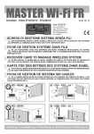
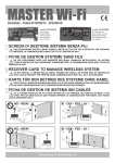
D - CONNECTING THE MASTER Wi-Fi CARD TO THE CONTROL PANEL
The MASTER Wi-Fi card when inserted on RIB electronic control panels is
protected against short circuits by a fuse connected to the secondary of the power
supply.
When using a MASTER Wi-Fi card with control panels of other brands, please
verify the presence of this protection.
In case it is not available, please connect a fuse with current of T 200 mA in series
on the power supply.
Turn off power to the automation control panel.
Couple or connect the MASTER Wi-Fi card and perform the connections as in the
following diagram.
NOTE: The opening of the gate occurs 2 seconds after receiving a radio or push
button command. That is done to allow the MASTER Wi-Fi card to verify the
presence and correct functioning of the memorized safety devices.
Furthermore, it is strongly advisable to avoid using an automatic closing time
delay, not longer than 1 minute.
*
PED
green wire
COM
gray wire
EDGE
yellow wire
PHOT.N.C. black wire
CONTROL BUTTON
white wire
A/D+ TEST brown wire
!
**
24V ac/dc
10 9
65
21
654321
+ 6
5
Total opening control contact COM-OPEN/K
!
* OBLIGATORY connection for panels with a 120/230V ac blinker output
** OBLIGATORY connection for panels with a 24V ac/dc blinker output
ATTENTION: CHECK POLARITY
The connection is compulsory also in those cases where the blinker is not
installed in the system.
ATTENTION: Always connect the control panel blinker output to the MASTER
Wi-Fi card with one of the dedicated terminals, depending on whether the blinker
is 230V or 24V. If the connection is not made the door will not work and the
buzzer emits 4 sounds indicating that the connection is missing.
PEDESTRIAN CONTROL (gray wire COM, green wire PED) dedicated to
pedestrian radio-control.
EDGE INPUT (gray wire COM, yellow wire EDGE) dedicated to the strip safety
device.
Attention: any wire jumper present on the COM-EDGE terminals of RIB control
panels must be removed.
PHOTOCELL INPUT (gray wire COM, black wire PHOT) dedicated to
the photocell safety devices.
Attention: any wire jumper present on the COM-PHOT terminals of RIB control
panels must be removed.
+ -
1 Central
antenna connection 433,92 MHz
2 Antenna ground
4+ 3+ Power feed 12/24V ac/dc
CONTROL BUTTON (gray wire COM, white wire N.O. BUTTON)
Input dedicated to a control button with N.O. contact.
This input is particularly useful for total safety when a system control button is
already present.
Disconnect the control button from the control panel and connect it to this whit
wire.
CONNECTION OF THE AUTO TEST INPUT (for compliance with standard
EN13849-2:2008)
- If the panel used is equipped with auto test place jumper JP1 as indicated in
the “SELF-TEST-ENABLED RIB ELECTRONIC BOARD CHART”, following.
- Connect the auto test output of the control panel to the A/D+ TEST terminal of
the MASTER Wi-Fi card in order to be able to control the system at the end of
every complete automated opening.
- Closing will only occur when the MASTER Wi-Fi card has passed the
control test.
- If the MASTER Wi-Fi card control test fails, the control panel will block the
automation, the dual-color LED on the MASTER Wi-Fi card indicates a safety
outage, alternately flashing red and green.
The buzzer emits an alternating sound for 1 minute to signal the problem.
The alarm status of the buzzer comes on again for 1 minute when a control is
given.
If the panel is not equipped with an auto test, the control test is ignored.
21