1
IEEE802.3ap 10GBASE-KR
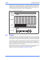
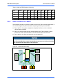
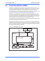
Figure 2-5
AXP1440 Shelf Description
Hub Slot Connectivity
U pd ate Ch ann el
ATCA Blade
Slot 6
Zone 2
nel
han
nel
eC
Bas
han
C
ric
Fab
ATCA Blade
Slot 9
U pd
Ba
s
l
ne l
an ne
Ch han
e
s C
Ba ric
b
Fa
Other Hub
ate
Cha
nne
l
SAM
eC
ha
nne
l
SAM
Backplane
Zone 1
_B
-48 V
_A
MB
A
8V
B_
-4
M
PEM A
2.7
IP
IP
H A[7:0],
L OGIC _GND ,
SH ELF_ GND,
Me tall ic, Ri ng
_B
SAM A
PEM B
SAM B
IEEE802.3ap 10GBASE-KR
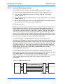
The AXP1440 backplane is designed to support 40Gb traffic via 10GBASE-KR. Currently, the
Centellis 4440 platform core switch does not support this.
2.8
Fan Tray Modules (FTMs)
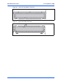
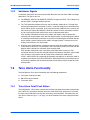
The AXP1440 supports 2 fan trays in a push/pull configuration. Each fan tray contains 6 dual
counter rotating fans. The lower fan tray is accessible from the front of the chassis and contains
the replaceable air filter. The upper fan tray is located in the rear of the chassis.
The FTM has a ejector handle which signals the IPM Sentry software for hot swap. If your
system is not running high-availability software, behavior of the LED may be indeterminate. The
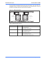
face plate of the upper and lower FTMs has the following indicators:
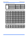
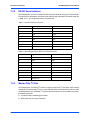
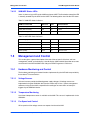
Table 2-7 FTM LED Status Indicators
FTM LED
LED Color
In-Service (IS)
Green
State/Condition
Off: no service
Blink: FTM activating
Glow Steady: service available
Out-of-Service (OOS) and Failure
Red (default)
Off: service available
Blink: Deactivation requested
Glow Steady: no service
Hot Swap (H/S)
Blue
Off: FTM is not ready to be removed
Blink: Deactivation requested
Glow Steady: FTM is ready to remove
Centellis 4440 Installation and Use (6806800H23A)
53