1
User Guide
SM-EtherCAT
Unidrive SP
Affinity
Digitax ST
Commander SK
Mentor MP
Part Number: 0471-0128-05
Issue Number: 5
www.controltechniques.com
General Information
The manufacturer accepts no liability for any consequences resulting from inappropriate, negligent or
incorrect installation or adjustment of the optional parameters of the equipment or from mismatching the
variable speed drive with the motor.
The contents of this guide are believed to be correct at the time of printing. In the interests of commitment
to a policy of continuous development and improvement, the manufacturer reserves the right to change the
specification of the product or its performance, or the content of the guide without notice.
All rights reserved. No parts of this guide may be reproduced or transmitted in any form or by any means,
electrical or mechanical including, photocopying, recording or by an information storage or retrieval system,
without permission in writing from the publisher.
Environmental Statement
Control Techniques is committed to minimising the environmental impacts of its manufacturing operations
and of its products throughout their life cycle. To this end, we operate an Environmental Management
System (EMS) which is certified to the International Standard ISO 14001. Further information on the EMS,
our Environment Policy and other relevant information is available on request, or can be found at
www.greendrives.com.
The electronic variable speed drives manufactured by Control Techniques have the potential to save
energy and (through increased machine/process efficiency) reduce raw material consumption and scrap
throughout their long working lifetime. In typical applications, these positive environmental effects far
outweigh the negative impacts of product manufacture and end-of-life disposal.
Nevertheless, when the products eventually reach the end of their useful life, they must not be discarded
but should instead be recycled by a specialist recycler of electronic equipment. Recyclers will find the
products easy to dismantle into their major component parts for efficient recycling. Many parts snap
together and can be separated without the use of tools, while other parts are secured with conventional
fasteners. Virtually all parts of the product are suitable for recycling.
Product packaging is of good quality and can be re-used. Large products are packed in wooden crates,
while smaller products come in strong cardboard cartons which themselves have a high-recycled fibre
content. If not re-used, these containers can be recycled. Polythene, used on the protective film and bags
from wrapping product, can be recycled in the same way. Control Techniques' packaging strategy prefers
easily recyclable materials of low environmental impact, and regular reviews identify opportunities for
improvement.
When preparing to recycle or dispose of any product or packaging, please observe local legislation and
best practice.
Software Statement
This Solutions Module (SM) is supplied with the latest software version. When retro-installing to an existing
system, all software versions should be verified to confirm the same functionality as Solutions Modules of
the same type already present. This also applies to products returned from a Control Techniques Service
Centre or Repair Centre. If there is any doubt please contact the supplier of the product.
The software version of the Solutions Module can be identified by looking at Pr MM.02 and Pr MM.51,
where MM is the relevant menu number for the Solutions Module slot being used.
See Pr MM.02 and Pr MM.51 description later in this manual for more information.
The software version takes the form of xx.yy.zz, where Pr MM.02 displays xx.yy and Pr MM.51 displays zz
(e.g. for software version 01.01.00 Pr 15.02 will display 1.01 and Pr 15.51 will display 0).
REACH legislation
EC Regulation 1907/2006 on the Registration, Evaluation, Authorisation and restriction of Chemicals
(REACH) requires the supplier of an article to inform the recipient if it contains more than a specified
proportion of any substance which is considered by the European Chemicals Agency (ECHA) to be a
Substance of Very High Concern (SVHC) and is therefore listed by them as a candidate for compulsory
authorisation.
For current information on how this requirement applies in relation to specific Control Techniques products,
please approach your usual contact in the first instance. Control Techniques position statement can be
viewed at:
http://www.controltechniques.com/REACH
Copyright
: © May 2011 Control Techniques Ltd.
Issue Number : 5
Contents
1
Safety information ..........................................................5
1.1
1.2
1.3
1.4
1.5
1.6
1.7
1.8
Warnings, cautions and notes ......................................................................5
Electrical safety - general warning ...............................................................5
System design and safety of personnel .......................................................5
Environmental limits .....................................................................................6
Compliance with regulations ........................................................................6
Motor ............................................................................................................7
Adjusting parameters ...................................................................................7
Electrical installation ....................................................................................7
2
Introduction ....................................................................8
2.1
2.2
2.3
2.4
2.5
2.6
Features .......................................................................................................8
Introduction to SM-EtherCAT .......................................................................8
What is EtherCAT? ......................................................................................8
Solution module identification ......................................................................9
Product Conformance Certificate .................................................................9
Conventions used in this guide ....................................................................9
3
Mechanical installation ................................................11
3.1
General installation ....................................................................................11
4
Electrical installation ...................................................12
4.1
4.2
4.3
4.4
4.5
SM-EtherCAT module information .............................................................12
SM-EtherCAT terminal descriptions ...........................................................12
Module grounding ......................................................................................13
Network topology .......................................................................................13
Minimum node-to-node cable length ..........................................................13
5
Getting started ..............................................................14
5.1
5.2
5.3
5.4
5.5
5.6
5.7
Quick start guide ........................................................................................14
Quick start flowchart ..................................................................................18
Saving parameters to the drive ..................................................................19
SM-EtherCAT Node address .....................................................................19
SM-EtherCAT RUN ....................................................................................19
Re-initializing the SM-EtherCAT ................................................................20
Re-initialize all Solutions Modules .............................................................20
6
Protocols .......................................................................21
6.1
6.2
6.3
6.4
Process Data Objects (PDOs) ...................................................................21
Service Data Object (SDO) parameter access ..........................................21
CANopen over EtherCAT (CoE) ................................................................22
Ethernet over EtherCAT (EoE) ..................................................................32
SM-EtherCAT User Guide
Issue Number: 5
www.controltechniques.com
3
4
7
Drive profile (DSP-402) support ..................................36
7.1
7.2
7.3
7.4
7.5
7.6
7.7
7.8
0x6040 Controlword ...................................................................................36
0x6041 Statusword ....................................................................................37
Common profile features ............................................................................37
Interpolated position mode .........................................................................48
vl velocity mode .........................................................................................50
Profile torque mode ....................................................................................56
Homing mode .............................................................................................57
Cyclic sync position mode ..........................................................................65
8
Advanced features .......................................................67
8.1
8.2
8.3
8.4
8.5
Distributed Clocks ......................................................................................67
SM-EtherCAT protocol support ..................................................................68
Menu 61 - General Module Setup ..............................................................68
Advanced cyclic data configuration ............................................................72
Internal shortcuts .......................................................................................73
9
Diagnostics ...................................................................74
9.1
9.2
9.3
9.4
9.5
9.6
9.7
9.8
9.9
9.10
9.11
9.12
Module identification parameters ...............................................................74
Network configuration objects ....................................................................75
Diagnostic parameters ...............................................................................76
Drive trip display codes ..............................................................................77
SM-EtherCAT module temperature ...........................................................77
SM-EtherCAT serial number ......................................................................77
SM-EtherCAT error codes .........................................................................77
Error handling ............................................................................................78
Critical task % free .....................................................................................80
SDO abort codes .......................................................................................81
FLASH file system % free ..........................................................................81
Updating SM-EtherCAT firmware ..............................................................82
10
Quick reference ............................................................83
11
Glossary of terms .........................................................87
www.controltechniques.com
SM-EtherCAT User Guide
Issue Number: 5
1.1
Warnings, cautions and notes
Introduction
Safety information
Safety
information
1
A Warning contains information, which is essential for avoiding a safety hazard.
A Caution contains information, which is necessary for avoiding a risk of damage to the
product or other equipment.
Electrical
installation
CAUTION
NOTE
A Note contains information, which helps to ensure correct operation of the product.
Electrical safety - general warning
The voltages used in the drive can cause severe electrical shock and/or burns, and
could be lethal. Extreme care is necessary at all times when working with or adjacent to
the drive.
Protocols
Specific warnings are given at the relevant places in this User Guide.
1.3
System design and safety of personnel
The drive uses high voltages and currents, carries a high level of stored electrical
energy, and is used to control equipment which can cause injury.
Glossary of
terms
The SAFE TORQUE OFF function is only available as standard on the Unidrive SP and
Digitax ST.
Quick
reference
With the sole exception of the SAFE TORQUE OFF function on Unidrive SP and
Digitax ST, none of the drive functions must be used to ensure safety of
personnel, i.e. they must not be used for safety-related functions.
Diagnostics
The STOP and SAFE TORQUE OFF functions of the drive do not isolate dangerous
voltages from the output of the drive or from any external option unit. The supply must
be disconnected by an approved electrical isolation device before gaining access to the
electrical connections.
Advanced
features
Close attention is required to the electrical installation and the system design to avoid
hazards either in normal operation or in the event of equipment malfunction. System
design, installation, start up and maintenance must be carried out by personnel who
have the necessary training and experience. They must read this safety information and
this User Guide carefully.
Drive profile (DSP-402)
support
The drive is intended as a component for professional incorporation into complete
equipment or a system. If installed incorrectly, the drive may present a safety hazard.
NOTE
Getting started
1.2
Mechanical
installation
WARNING
Index
SM-EtherCAT User Guide
Issue Number: 5
www.controltechniques.com
5
Careful consideration must be given to the functions of the drive which might result in a
hazard, either through their intended behavior or through incorrect operation due to a
fault. In any application where a malfunction of the drive or its control system could lead
to or allow damage, loss or injury, a risk analysis must be carried out, and where
necessary, further measures taken to reduce the risk - for example, an over-speed
protection device in case of failure of the speed control, or a fail-safe mechanical brake
in case of loss of motor braking.
The SAFE TORQUE OFF function has been approved by BGIA as meeting the
requirements of the following standards, for the prevention of unexpected starting of the
drive:
EN 61800-5-2:2007 SIL 3
EN ISO 13849-1:2006 PL e
EN 954-1:1997 Category 3
The SAFE TORQUE OFF function may be used in a safety-related application. The
system designer is responsible for ensuring that the complete system is safe and
designed correctly according to the relevant safety standards.
1.4
Environmental limits
Instructions in the Unidrive SP User Guide, Commander SK Getting Started Guide,
Commander SK Technical Data Guide, Digitax ST User Guide and Mentor MP User
Guide regarding transport, storage, installation and use of the drive must be complied
with, including the specified environmental limits. Drives must not be subjected to
excessive physical force.
1.5
Access
Drive access must be restricted to authorized personnel only. Safety regulations which
apply at the place of use must be complied with.
1.6
Fire protection
The drive enclosure is not classified as a fire enclosure. A separate fire enclosure must
be provided.
1.7
Compliance with regulations
The installer is responsible for complying with all relevant regulations, such as national
wiring regulations, accident prevention regulations and electromagnetic compatibility
(EMC) regulations. Particular attention must be given to the cross-sectional areas of
conductors, the selection of fuses or other protection, and protective earth (ground)
connections.
The Unidrive SP User Guide, Digitax ST User Guide and Mentor MP User Guide
contain instructions for achieving compliance with specific EMC standards.
Within the European Union, all machinery in which this product is used must comply
with the following directives:
•
•
6
2006/42/EC: Safety of machinery.
2004/108/EC: Electromagnetic Compatibility.
www.controltechniques.com
SM-EtherCAT User Guide
Issue Number: 5
Motor
Ensure the motor is installed in accordance with the manufacturer’s recommendations
and that the motor shaft is not exposed.
The values of the motor parameters set in the drive affect the protection of the motor.
The default values in the drive should not be relied upon.
Adjusting parameters
Some parameters have a profound effect on the operation of the drive. They must not
be altered without careful consideration of the impact on the controlled system.
Measures must be taken to prevent unwanted changes due to error or tampering.
Protocols
1.10
Electrical installation
1.10.1 Electric shock risk
Drive profile (DSP-402)
support
The voltages present in the following locations can cause severe electric shock and
may be lethal:
•
•
•
Getting started
1.9
Electrical
installation
It is essential that the correct value is entered in the motor rated current parameter,
Pr 5.07 (or Pr 0.46 in Unidrive SP, Affinity and Digitax ST, or Pr 0.28 {SE07} in Mentor
MP, or Pr 0.06 in Commander SK). This affects the thermal protection of the motor.
Mechanical
installation
Low speeds may cause the motor to overheat because the cooling fan becomes less
effective. The motor should be installed with a protection thermistor. If necessary, an
electric forced vent fan should be used.
Introduction
Standard squirrel cage induction motors are designed for single speed operation. If it is
intended to use the capability of the drive to run a motor at speeds above its designed
maximum, it is strongly recommended that the manufacturer is consulted first.
Safety
information
1.8
AC supply cables and connections
Output cables and connections
Many internal parts of the drive, and external option units
Unless otherwise indicated, control terminals are single insulated and must not be
touched.
Diagnostics
The drive contains capacitors that remain charged to a potentially lethal voltage after
the AC supply has been disconnected. If the drive has been energized, the AC supply
must be isolated at least ten minutes before work may continue.
Advanced
features
1.10.2 Stored charge
Quick
reference
Glossary of
terms
Index
SM-EtherCAT User Guide
Issue Number: 5
www.controltechniques.com
7
2
Introduction
2.1
Features
•
Standard RJ45 with support for shielded twisted pair, half-duplex / full-duplex and
10Mbs / 100Mbs connectivity
•
Dual 100Mbps EtherCAT interfaces for use in line topologies i.e. daisy chaining
•
Supports the Unidrive SP drives range, Mentor MP, Affinity, Digitax ST and
Commander SK
•
Control loop synchronization
•
Control cycle times down to 250µs
•
Configured Station Alias
•
CANopen over EtherCAT (CoE) which includes:
•
•
2.2
Support of CANopen DSP-402 (Device Profile for Drives and Motion)
•
Cyclic sync position mode
•
Interpolated position mode
•
Velocity mode
•
Profile torque mode
•
Homing mode
•
Two transmit and two receive PDOs
•
SDO access to all profile objects and drive parameters
•
Two digital inputs available for use in homing mode
EoE (Ethernet over EtherCAT)
Introduction to SM-EtherCAT
SM-EtherCAT is a Solutions Module that enables the Control Techniques range of
variable speed drives to be connected to an EtherCAT network as a slave device. It can
be used in a variety of applications, from those requiring accurate synchronization and
precise motion control, to those where ease of use and open loop control are
appropriate.
2.3
What is EtherCAT?
EtherCAT is an open high performance Ethernet-based fieldbus system that overcomes
the system limitations of other Ethernet solutions. The Ethernet packet is no longer
received, then interpreted and copied as process data at every connection; instead the
Ethernet frame is processed on the fly. The development goal of EtherCAT was to apply
Ethernet to automation applications that require short data update times (also called
cycle times) with low communication jitter (for synchronization purposes) and low
hardware costs. Typical application fields for EtherCAT are machine controls (e.g.
semiconductor tools, metal forming, packaging, injection moulding, assembly systems,
printing machines, robotics and many others).
8
www.controltechniques.com
SM-EtherCAT User Guide
Issue Number: 5
Solution module identification
Safety
information
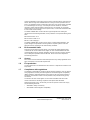
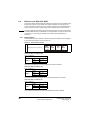
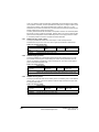
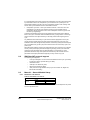
2.4
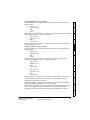
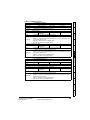
The SM-EtherCAT can be identified by:
1. The label located on the underside of the Solutions Module.
2. The color coding across the front of the SM-EtherCAT (brown-red).
Introduction
Figure 2-1 SM-EtherCAT label
Solutions Module
name
Hardware
issue
number
Customer
and date code
stdJ 41
Ser No :3000005001
Serial number
Electrical
installation
2.4.1
Revision
: 0
Mechanical
installation
SM-EtherCAT
Date code format
The letter indicates the year and the number indicates the week number (within the
year) in which the Solutions Module was built.
The letters are alphabetical in order, starting with A in 1991 (B in 1992, C in 1993 etc.).
Protocols
Example:
A date code of Q46 would correspond to week 46 of year 2007.
Product Conformance Certificate
Drive profile (DSP-402)
support
2.5
SM-EtherCAT has been awarded full EtherCAT Conformance Certification by the
EtherCAT Technology Group (ETG). A copy of the certificate is available on request
from your supplier or local Control Techniques Drive Centre.
2.6
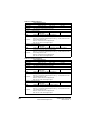
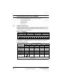
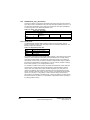
Conventions used in this guide
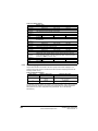
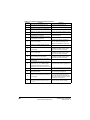
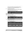
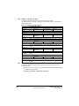
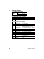
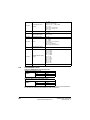
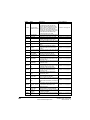
The method used to determine the menu or parameter is as follows:
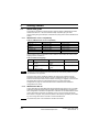
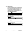
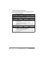
Table 2.1 Drive menu availability
Slot 1
15.xx
Slot 2
16.xx
Slot 3
17.xx
Yes
Yes
Yes
Affinity
Yes
Yes
No
Mentor MP
Yes
Yes
Yes
Commander SK
Yes
No
No
Digitax ST
Yes
Yes
No
SM-EtherCAT User Guide
Issue Number: 5
www.controltechniques.com
Index
Unidrive SP
Glossary of
terms
Drive Type
Quick
reference
Pr xx.00 - signifies any menu and parameter number 00.
Pr MM.xx - where MM signifies the menu allocated to the solutions module (as
shown in Table 2.1 Drive menu availability ) and xx signifies the parameter number.
Diagnostics
In the case of a Solutions Module, the parameters will appear in one of three menus 15,
16 or 17 depending on the drive type and slot the module is installed into as shown in
Table 2.1 Drive menu availability below. The menu is denoted by the number before the
decimal point.
Advanced
features
The configuration of the host drive and Solutions Module is done using menus and
parameters. A menu is a logical collection of parameters that have similar functionality.
•
•
Getting started
The date code is split into two sections: a letter followed by a number.
9
NOTE
All references in this manual to SM-Applications/Plus should also extend to SM-Applications Lite/Lite V2. The exceptions to this are references to SM-Applications/Plus input/
output, CTSync or the EIA (RS) -485 port, as these are not supported on SM-Applications Lite/Lite V2. For full details of the differences see the SM-Applications Modules and
Motion Processors User Guide.
NOTE
It is strongly recommended that the latest firmware be used where possible to ensure
that all features are supported.
10
www.controltechniques.com
SM-EtherCAT User Guide
Issue Number: 5
Before installing or removing a Solutions Module in any drive, ensure the AC supply has
been disconnected for at least 10 minutes and refer to Chapter 1 Safety information on
page 5. If using a DC bus supply ensure this is fully discharged before working on any
drive or Solutions Module.
General installation
Mechanical
installation
3.1
Mechanical installation
Introduction
WARNING
Safety
information
3
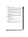
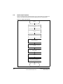
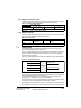
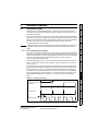
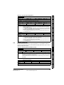
The installation of a Solutions Module is illustrated in Figure 3-1.
Figure 3-1 Installing a Solutions Module
Getting started
2
Electrical
installation
1
Protocols
Drive profile (DSP-402)
support
Advanced
features
The Solutions Module connector is located on the underside of the module (1). Push
this into the Solutions Module slot located on the drive until it clicks into place (2). Note
that some drives require a protective tab to be removed from the Solutions Module slot.
For further information, refer to the appropriate drive manual.
Diagnostics Quick reference
Glossary of
terms
Index
SM-EtherCAT User Guide
Issue Number: 5
www.controltechniques.com
11
4
Electrical installation
4.1
4.1.1
SM-EtherCAT module information
Bus media
The SM-EtherCAT option module incorporates two 100 BASE-TX RJ45 interfaces.
4.1.2
Cabling considerations
To ensure long-term reliability it is recommended that any cables used to connect a
system together be tested using a suitable Ethernet cable tester, this is of particular
importance when cables are constructed on site.
4.1.3
Cable
Cables should be shielded and as a minimum, meet TIA Cat 5e requirements.
NOTE
4.1.4
Cabling issues are the single biggest cause of network downtime. Ensure cabling is
correctly routed, wiring is correct, connectors are correctly installed and any switches or
routers used are rated for industrial use. Office grade Ethernet equipment does not
generally offer the same degree of noise immunity as equipment intended for industrial
use.
Maximum network length
The main restriction imposed on Ethernet cabling is the length of a single segment of
cable. The SM-EtherCAT module has two 100BASE-TX Ethernet ports, which support
segment lengths of up to 100m. This means that the maximum cable length which can
be used between one SM-EtherCAT port and another 100BASE-TX port is 100m
however it is not recommended that the full 100m cable length is used. The total
network length is not restricted by the Ethernet standard but depends on the number of
devices on the network and the transmission media (copper, fiber optic, etc.).
NOTE
4.2
The EtherCAT system designer must consider the impact that the selected network
structure will have on performance.
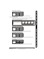
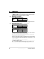
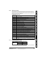
SM-EtherCAT terminal descriptions
The SM-EtherCAT module has two RJ45 Ethernet ports for the EtherCAT network.
There are also two digital inputs available for use in Homing Mode.
Figure 4-1 EtherCAT connection
A
B
A
12
1
2
3
B
www.controltechniques.com
SM-EtherCAT User Guide
Issue Number: 5
Pin
B - OUT
Digital Inputs
Function
Transmit +
1
Transmit +
1
0V Common
2
Transmit -
2
Transmit -
2
Digital input 0
3
Receive +
3
Receive +
3
Digital input 1
4
Not used
4
Not used
5
Not used
5
Not used
6
Receive -
6
Receive -
7
Not used
7
Not used
8
Not used
8
Not used
Mechanical
installation
A - IN
1
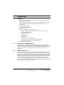
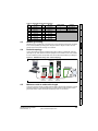
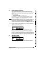
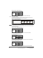
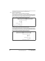
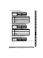
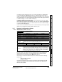
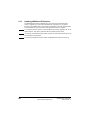
Figure 4-2 SM-EtherCAT daisy chain network topology
Digitax ST
Drive profile (DSP-402)
support
Unidrive SP
Master / PLC
Protocols
Control Techniques recommend implementing daisy chaining on EtherCAT networks
(see Figure 4-2). Other Ethernet network topologies can be used but care must be taken
to ensure that the system still operates within the constraints specified by the designer.
Getting
started
Network topology
Electrical
installation
Module grounding
SM-EtherCAT is supplied with a grounding tag on the module that should be connected
to the closest possible grounding point using the minimum length of cable. This will
greatly improve the noise immunity of the module.
4.4
Introduction
4.3
Pin
Safety
information
Table 4.1 EtherCAT terminal descriptions
Commander SK
Distributed I/O
Advanced
features
SM EtherCAT
Minimum node-to-node cable length
There is no minimum length of cable recommended in the Ethernet standards. To avoid
possible problems it is recommended that you allow sufficient cable length to ensure
good bend radii on cables and avoid unnecessary strain on connectors.
Quick
reference
4.5
SM EtherCAT
Diagnostics
SM EtherCAT
Glossary of
terms
Index
SM-EtherCAT User Guide
Issue Number: 5
www.controltechniques.com
13
5
Getting started
5.1
Quick start guide
This section is intended to provide a generic guide for setting up SM-EtherCAT with a
master/controller PLC. It will cover the basic steps required to get cyclic data
communicating using the CANopen over EtherCAT (CoE) protocol on the SM-EtherCAT
module.
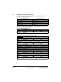
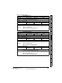
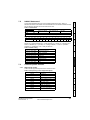
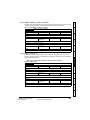
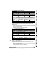
5.1.1
SM-EtherCAT version compatibility
Table 5.1 SM-EtherCAT version compatibility
Drive type
Drive firmware
SM-EtherCAT firmware
Unidrive SP
V01.08.00 or later
V01.00.00 or later
Affinity
V01.02.00 or later
V01.00.00 or later
Digitax ST
V01.02.00 or later
V01.00.00 or later
Commander SK
V01.06.00 or later
V01.00.00 or later
Mentor MP
V01.00.00 or later
V01.02.00 or later
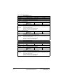
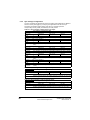
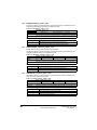
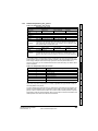
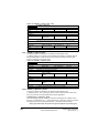
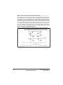
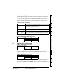
For the purpose of the example this section will follow the steps required to set up cyclic
communications using one RxPDO and two TxPDOs. These PDOs will consist of the
mappings shown in Table 5.2:
Table 5.2 PDO test mappings
RxPDO1
0x6040 (controlword)
Mapping 1
(16-bits)
Mapping 2
0x6042 (vl_target_velocity)
(16-bits)
Mapping 3 Pr 20.21 (32-bits)
NOTE
TxPDO1
TxPDO6
0x6041 (statusword)
(16-bits)
Pr 18.22 (16-bits)
0x6064
(position_actual_value)
(32-bits)
Pr 20.21 (32-bits)
N/A
N/A
It is strongly recommended that the latest firmware be used where possible to ensure
that all features are supported.
Due to the large number of different masters that support CoE, details cannot be
provided for a specific master. Generic support is available through your supplier or
local Control Techniques Drive Centre. Before contacting your supplier or local Control
Techniques Drive Centre for support please ensure you have read section
9 Diagnostics on page 74 of this manual and have checked that the SDO/PDO
configurations are correct.
5.1.2
SM-EtherCAT XML file
Control Techniques provides EtherCAT device description files (in the form of .xml files).
These files provide the master with information about the SM-EtherCAT module and
drive configuration to aid with its configuration. These files can be downloaded from the
Control Techniques CTSupport.com website or from your local Control Techniques
Drive Centre or supplier. They should be placed in the directory specified by the master
e.g. when using TwinCAT this could be C:\TwinCAT\Io\EtherCAT.
NOTE
14
The master may have to be re-started for the file to be loaded.
www.controltechniques.com
SM-EtherCAT User Guide
Issue Number: 5
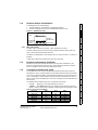
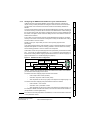
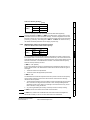
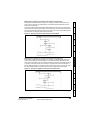
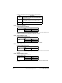
Configuring the SM-EtherCAT module for cyclic communications
Decide on the input / output data you wish to send cyclically (objects and/or
parameters).
Cyclic data is implemented on CoE networks by using "Process Data Objects" or PDOs.
Separate data objects are used for receiving (TxPDOs - from the slave to the master)
and transmitting (RxPDOs - from the master to the slave) data.
RxPDO1
0x6040
Control word
0x6042
vl_target_velocity
Pr 20.21
PLC
TxPDO1
Drive profile (DSP-402)
support
Figure 5-1 SM-EtherCAT PDO configuration
Protocols
These PDOs contain the cyclic data (objects and/or parameters), the RxPDOs available
are 1, 2, 6 and 22, the TxPDOs available are 1, 2, 3, 6 and 22 (for more information on
these PDOs including default mappings please see section 6.3.2 RxPDO mappings on
page 24 and section 6.3.3 TxPDO mappings on page 27).
Electrical
Getting started
installation
In the master, scan the network ensuring that the SM-EtherCAT module is connected
correctly to the master. If the network is configured correctly the SM-EtherCAT node(s)
should be visible in the PLC master.
Mechanical
installation
To check that the ethernet cable connected to the SM-EtherCAT module on the drive is
connected correctly, look at the LED on the front of the SM-EtherCAT module relating to
the connector being used, if this light is a solid green color then a link is established with
the master, if this light if off then check the cabling and also check that the master has
started communications.
Introduction
Unlike other Control Techniques fieldbus communication protocols, CoE does not
require that any module parameters be changed in order to achieve communications.
The baud rate of the network is fixed and the module is automatically allocated an
address.
Safety
information
5.1.3
TxPDO6
0x6064 position
actual value
Pr 18.22
Advanced
features
0x6041
Status word
Pr 20.22
The format used when mapping objects to PDOs is as follows:
Index: Object index number (0x0000)
•
Sub-index: Object sub-index number (0x00)
•
Size: Dependant on the size (in bytes) of the object to be mapped (range: 1-4)
The format used when mapping drive parameters to PDOs is as follows:
Index: 0x2000 + menu number
•
Sub-index: 0x00 + parameter number
•
Size: Dependant on the size (in bytes) of the object to be mapped (range: 1-4)
Glossary of
terms
•
Quick reference
•
Diagnostics
RxPDO1, TxPDO1 and TxPDO6 will need to be enabled in the master. Once enabled
you will need to add mappings to the PDOs.
For example Pr 20.21 would be index 0x2014, sub-index 0x15 and the size would be 4
(the parameter is a 32-bit signed value).
The values are normally expressed in hexadecimal, so care must be taken to enter the
correct parameter number.
SM-EtherCAT User Guide
Issue Number: 5
www.controltechniques.com
15
Index
NOTE
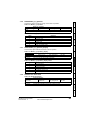
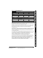
For this example the following objects will need to be set in order to achieve the
mappings of the parameters/objects in the PDOs.
Table 5.3 Cyclic data mapping configuration
RxPDO1:
TxPDO1:
TxPDO6:
Object:
0x1600
Object:
0x1A00
Object:
0x1A05
Sub-index:
0x00
Sub-index:
0x00
Sub-index:
0x00
Size:
1
Size:
1
Size:
1
Value:
3
Value:
2
Value:
2
Sub-index:
0x01
Sub-index:
0x01
Sub-index:
0x01
Size:
4
Size:
4
Size:
4
Value:
0x60400010
Value:
0x60410010
Value:
0x20121610
Sub-index:
0x02
Sub-index:
0x02
Sub-index:
0x02
Size:
4
Size:
4
Size:
4
Value:
0x60420010
Value:
0x60640020
Value:
0x20141620
Sub-index:
0x03
Not Used
Size:
4
Value:
0x20141520
Not Used
NOTE
The format used to define the value of a mapped object is as follows:
Bit 0 to 7: Length of the mapped object in bits (if a gap, bit length of the gap).
Bit 8 to 15: Sub-index of the mapped object (if a gap, zero).
Bit 16 to 31: Index of the mapped object (if a gap, zero).
NOTE
The maximum number of mappings in one PDO is five. There are no restrictions on the
data length of these 5 parameters (i.e. It is possible to map five, 32-bit parameters in
one PDO). It is also possible to use a maximum of two RxPDOs and two TxPDOs.
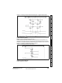
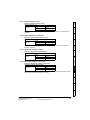
5.1.4
Configuring the sync managers
The sync manager is used to control the transmission of CANopen PDOs over the
EtherCAT network.
The following objects 0x1C12 - sync manager 2 PDO assignment (RxPDO) and 0x1C13
- sync manager 3 PDO assignment (TxPDO) are required to assign PDOs to the
synchronization task. For the purpose of the example assign one RxPDO to sync
manager 2 and two TxPDOs to sync manager 3.
Figure 5-2 SM-EtherCAT sync manager configuration
0x1C12
RxPDO1
0x6040
Control word
PLC
0x6042
vl_target_velocity
0x1C13
TxPDO1
0x6041
Status word
16
Pr 20.21
TxPDO6
0x6064
position
actual value
Pr 18.22
www.controltechniques.com
Pr 20.22
SM-EtherCAT User Guide
Issue Number: 5
Index: 0x1C12
•
Sub index: 0x00
•
Size: 1
•
Value: 1
Introduction
•
Sub index: 0x01
•
Size: 2
•
Value: 0x1600
Setting object 0x1C12, sub-index 1 to a value of 0x1600 (as above) maps RxPDO1 to
the process data output sync.
Assigning TxPDO to the sync manager
To assign TxPDO1 to sync manager 3 PDO assignment set the values below to the
following objects:
Sub index: 0x00
•
Size: 1
•
Value: 2
Drive profile (DSP-402)
support
Index: 0x1C13
•
Protocols
•
Setting object 0x1C13, sub-index 0 to a value of 2 (as above) indicates that two
TxPDOs will be assigned to the sync manager 3 assignment.
Sub index: 0x01
•
Size: 2
•
Value: 0x1A00
•
Index: 0x1C13
•
Sub index: 0x02
•
Size: 2
•
Value: 0x1A05
Diagnostics
Index: 0x1C13
•
Advanced
features
•
Electrical
Getting started
installation
Index: 0x1C12
•
Mechanical
installation
Setting object 0x1C12, sub-index 0 to a value of 1 (as above) indicates that one RxPDO
will be assigned to the sync manager 2 assignment.
•
Safety
information
Assigning RxPDO to the sync manager
To assign RxPDO1 to sync manager 2 PDO assignment set the values below to the
following objects:
Download the configuration to the master.
Values written to parameters over RxPDOs should now be viewable using the drive’s
keypad so long as the master has put the slave into the operational state; also,
parameter values changed using the drive keypad will be updated on the master.
Glossary of
terms
After downloading the configuration to the master the LED(s) on the front of the SMEtherCAT should flash, depending on the port(s) connected.
Quick reference
Setting object 0x1C13, sub-index 1 to a value of 0x1A00 and sub-index 2 to a value of
0x1A05 (as above) maps TxPDO1 and TxPDO6 to the process data input sync.
Index
SM-EtherCAT User Guide
Issue Number: 5
www.controltechniques.com
17
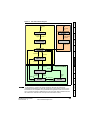
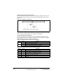
5.2
Quick start flowchart
Figure 5-3 details the steps required to achieve cyclic communications on the EtherCAT
network. This flowchart should be used as the starting point for all configurations.
Figure 5-3 Quick start flowchart
START
Ensure the Control Techniques .xml file is in
the appropriate folder on the hard drive of the
master
Check the LED status of the SM-EtherCAT
module
In the master, scan the EtherCAT network
Select required PDOs
Configure the PDOs with the mappings
required
Configure the Sync managers using the
required PDOs
Download or activate the configuration to the
master
Check the front of the SM-EtherCAT module
to ensure that the LED relating to the
connection being used is flashing, this
confirms that communications are functioning
END
18
www.controltechniques.com
SM-EtherCAT User Guide
Issue Number: 5
Saving parameters to the drive
To store drive parameters:
Set Pr MM.00 to 1000 (Mentor MP, Pr MM.00=SAVE).
Press the red RESET button.
Mechanical
installation
•
•
The drive will store all parameters (except Menu 20) but the operation of the SMEtherCAT will not be affected. Changes made to the SM-EtherCAT configuration
parameters will not take effect until the SM-EtherCAT is reset.
Unidrive-SP, Mentor MP, Affinity and Digitax ST: Menu 20 applications parameters may
be saved if an Applications Module is installed, menu 20 is stored in the Applications
Module’s memory. See the relevant Applications Module documentation for more
information. If the drive is running on backup supply only, Pr MM.00 must be set to 1001
to perform a save.
NOTE
This saves only drive and module parameters and not SM-EtherCAT related objects.
Protocols
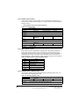
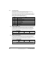
SM-EtherCAT Node address
Table 5.4 SM-EtherCAT Node address
Default
0
Range
0 to 65535
Access
RW
Diagnostics
5.5
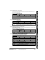
SM-EtherCAT RUN
Table 5.5 SM-EtherCAT RUN
Default
Quick reference
SM-EtherCAT RUN
Pr MM.04
1
Range
1 to 8
Access
RW
Advanced
features
It is not necessary for a user to set a node address manually in order to initiate
EtherCAT communications; however, this parameter can be used to configure an
EtherCAT Station Alias. When changed, this value will be stored in the option nonvolatile storage upon a transition from the INIT state to the PRE-OPERATIONAL state;
this change will also cause an AL Status Code to be set to indicate that the option needs
to be reset. It will be possible to read the value at the 16-bit word address 0x0004 of the
SII (Slave Information Interface) data, and in EtherCAT register 0x0012 (a 16-bit word).
Drive profile (DSP-402)
support
SM-EtherCAT Node address
Pr MM.03
Electrical
Getting started
installation
NOTE
5.4
Introduction
On the Unidrive SP, Affinity, Digitax ST and Commander SK to avoid loss of the
configured settings when the drive is powered down it is necessary to write 1000 to
Pr MM.00 followed by pressing the reset button to perform a drive save. On Mentor MP
Pr MM.00 needs to be set to a value of ‘SAVE’ followed by pressing the reset button.
Safety
information
5.3
Glossary of
terms
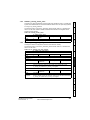
This parameter displays the SM-EtherCAT RUN state as required by the EtherCAT
indicator and Marking Specification. It will contain one of the values in Table 5.6.
Index
SM-EtherCAT User Guide
Issue Number: 5
www.controltechniques.com
19
Table 5.6 EtherCAT State Machine State
Value
ESM State
1
INIT
2
PRE-OPERATIONAL
4
SAFE-OPERATIONAL
8
OPERATIONAL
Although this parameter has the read/write attribute, it will be forced to the state value
continuously to prevent it being written by another entity.
5.6
Re-initializing the SM-EtherCAT
Table 5.7 SM-EtherCAT re-initialize
SM-EtherCAT re-initialize
Default
Pr MM.32
0 (OFF)
Range
0 (OFF) to 1 (ON)
Access
RW
Changes to the SM-EtherCAT configuration in menu 15, 16 or 17 parameters on
Unidrive SP and Mentor MP, menu 15 or 16 on Affinity and Digitax ST or menu 15 on
Commander SK will not take effect until the SM-EtherCAT has been re-initialized.
To re-initialize SM-EtherCAT:
1. Set Pr MM.32 to ON.
2. When the sequence has been completed, Pr MM.32 will be reset to OFF.
3. The SM-EtherCAT will re-initialize using the updated configuration.
NOTE
5.7
The above sequence does NOT store the SM-EtherCAT configuration parameters in the
drive or the SM-EtherCAT’s internal FLASH memory. This parameter will change back to
OFF immediately and as such the change may not be visible on the display.
Re-initialize all Solutions Modules
To re-initialize all Solutions Modules installed on a drive:
1. Set Pr MM.00 to 1070 (see note below).
2. Press the red RESET button on the drive. Another parameter (e.g. Pr 01.00) must
be used.
NOTE
This sequence does NOT store the SM-EtherCAT configuration parameters in the drive
or the SM-EtherCAT FLASH memory.
NOTE
On Commander SK drives, Pr 00.00 is not available.
20
www.controltechniques.com
SM-EtherCAT User Guide
Issue Number: 5
Safety
information
Protocols
6.1
Process Data Objects (PDOs)
6.1.1
PDO Priority
Protocols
It is possible to map any drive parameters in PDOs.
6.2
Service Data Object (SDO) parameter access
Index: 0x2000 + menu
Sub-index: parameter
Sub-index 0 for any menu will return the highest sub-index available for the object (i.e.
the highest parameter number). Pr MM.00 in any drive can only be accessed as
Pr 61. 01 (0x203D, sub-index changes to 1).
NOTE
The following SDO services are supported:
Glossary of
terms
Initiate SDO Download (Write)
Initiate SDO Upload (Read)
Abort SDO Transfer (Error)
Quick
reference
NOTE
Diagnostics
All other supported entries in the SM-EtherCAT object dictionary can also be accessed
using SDOs. Refer to the master controller documentation for full details about
implementing SDO transfers within the particular master controller.
Advanced
features
For example Pr 20.21 would be index 0x2014 and the sub-index would be 0x15. The
values are usually expressed in base 16 (hexadecimal), so care must be taken to enter
the correct parameter number.
Drive profile (DSP-402)
support
The service data object (SDO) provides access to all objects in the EtherCAT object
dictionary and the drive parameters are mapped into the object dictionary as 0x2XXX
objects in the following way:
•
•
•
Getting started
Mappings to slow parameters (such as SM-Applications PLC parameters, etc) should
always be placed in the second PDO. When there is more than one PDO mapping in a
Sync Manager, placing a slow parameter in the first PDO will trigger an SDO abort code.
If only one PDO is mapped to a sync manager, then placing a slow parameter in that
PDO will make it low priority (so slow parameter accesses should not be placed in
PDOs where deterministic data access is required).
Electrical
installation
If 2 PDOs are mapped in a sync manager then the second PDO will always be
considered to be low priority (and, as such, should not be used for deterministic process
data).
Mechanical
installation
Cyclic data is implemented on EtherCAT networks by using "Process Data Objects" or
PDOs. Separate data objects are used for transmitting (TxPDOs) and receiving
(RxPDOs) data. PDO configuration objects are usually pre-configured in the EtherCAT
master controller and downloaded to the SM-EtherCAT at network Initialization using
SDOs.
Introduction
6
Index
SM-EtherCAT User Guide
Issue Number: 5
www.controltechniques.com
21
6.3
CANopen over EtherCAT (CoE)
The CoE protocol over EtherCAT uses a modified form of the CANopen object
dictionary. This is specified in Table 6.1.
Table 6.1 CoE object dictionary
Index
Object dictionary area
0x0000 to 0x0FFF
Data type area
0x1000 to 0x1FFF
CoE communication area
0x2000 to 0x5FFF
Manufacturer specific area
0x6000 to 0x9FFF
Profile area
0xA000 to 0xFFFF
Reserved area
The object description format describes object related information such as size, range
and descriptions and is detailed in Table 6.2.
Table 6.2 Object description format
<index>
<object name>
Access: <access>
Range: <range>
Default:
<default>
Description:
<description>
Size: <size>
Unit: <unit>
For entries having sub-indices
Table 6.3 Object description format with sub-indices
<index>
<object name>
Sub-index 0
Access: <access>
Range: <range>
Default:
<default>
Description:
<description>
Size: <size>
Unit: <unit>
Size: <size>
Unit: <unit>
Size: <size>
Unit: <unit>
Size: <size>
Unit: <unit>
Size: <size>
Unit: <unit>
Sub-index 1
Access: <access>
Range: <range>
Default:
<default>
Description:
<description>
...
Access: <access>
Range: <range>
Default:
<default>
Description:
<description>
Sub-index n-1
Access: <access>
Range: <range>
Default:
<default>
Description:
<description>
Sub-index n
Access: <access>
22
Range: <range>
Default:
<default>
Description:
<description>
www.controltechniques.com
SM-EtherCAT User Guide
Issue Number: 5
<index> : A signed 16-bit number. This is the index of the object dictionary
entry specified in four hexadecimal characters.
•
<access> : A value describing how the object may be accessed (RW = read/
write, RO = read-only and WO = write-only).
•
<size> : The size of the object/sub-index in bytes.
•
<unit> : The physical unit (e.g. ms, counts per second etc.).
Mechanical
installation
CoE communication area
The first set of objects specify general communication settings.
Table 6.4 Device type object
Access: RO
Default:
Device type
Range: N/A
Size: 4 bytes
Unit: N/A
0x00030192
Drive profile (DSP-402)
support
This value will depend on the drive operating mode and/or type. On a Unidrive
SP in open-loop or closed-loop mode or a Mentor MP in closed-loop mode, bit 16
will be set, while bits 17 and 24 will be cleared. On a Unidrive SP in Servo mode
or a Digitax ST, bit 17 will be set, while bits 16 and 24 will be cleared.
Protocols
Description:
Bits 0 to 15 (Device profile number): 402 (0x192)
Bit 16 (Frequency converter): x
Bit 17 (Servo drive): y
Bit 18 (Stepper motor): 0
Bit 24 (DC drive - manufacturer specific : z
Bits 25 to 31 (Manufacturer specific): 0
Getting started
The primary CoE functional profile is DSP-402, the value of the object is defined
as follows:
Electrical
installation
0x1000
Introduction
6.3.1
•
Safety
information
Definitions:
Advanced
features
Diagnostics
Quick
reference
Glossary of
terms
Index
SM-EtherCAT User Guide
Issue Number: 5
www.controltechniques.com
23
Table 6.5 Identity object
0x1018
Identity object
Sub-index 0
Access: RO
Range: N/A
Size: 1 byte
Default:
4
Description:
The number of the last sub-index in this object.
Unit: N/A
Sub-index 1
Access: RO
Range: N/A
Size: 4 bytes
Unit: N/A
Default:
0x000000F9
Description:
This contains the EtherCAT Technology Group vendor ID for Control Techniques
(0x000000F9).
Sub-index 2
Access: RO
Range: N/A
Size: 4 bytes
Default:
See Pr MM.01
Description:
This has the value of the option ID code.
Unit: N/A
Sub-index 3
Access: RO
Range: N/A
Size: 4 bytes
Unit: N/A
Default:
High word: Pr MM.02 Low word: Pr MM.51
Description:
Contains the option module software version number (the major and minor
version parameter placed in the high word of this object, and the sub-version
parameter (Pr MM.51) is the low word).
Sub-index 4
Access: RO
6.3.2
Range: N/A
Size: 4 bytes
Default:
See Pr MM.35
Description:
Contains the option hardware serial number.
Unit: N/A
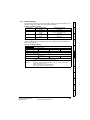
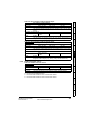
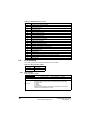
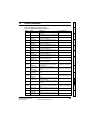
RxPDO mappings
Objects with indices from 0x1600 to 0x17FF specify receive PDO mappings. The
mappings from DSP-402 are included as standard (the PDO mappings will have the
following default values).
Table 6.6 RxPDO mappings
PDO number
Mapping object index
1
0x6040
Mapping object name
controlword
2
0x6040
0x6060
controlword
modes of operation
6
0x6040
0x6042
controlword
vl_target _velocity
The RxPDO mapping objects are defined in the following tables. Each mapping object
has the maximum number of sub-indices (each representing an object mapped to a
PDO) defined in the XML configuration file (specified as “CF” in the following
descriptions).
24
www.controltechniques.com
SM-EtherCAT User Guide
Issue Number: 5
0x1600
Safety
information
Table 6.7 RxPDO mapping 1
Receive PDO mapping 1
Sub-index 0: Number of mapped objects
Access: RW
Range: 0 to (CF)
Size: 1 byte
1
Description:
The number of mapped objects in thie PDO
Unit: N/A
Introduction
Default:
Sub-index 1: 1st mapped object
Default:
Size: 4 bytes
Unit: N/A
Mechanical
installation
Range: 0 to
0xFFFFFFFF
Access: RW
0x60400010 - the DSP-402 control word (0x6040)
A mapping to an object with the following format:
Bits 0 to 7: Length of the mapped object in bits, e.g. a 32-bit parameter would
have a length of 32 or 0x20.
Bits 8 to 15: Sub-index of the mapped object.
Bits 16 to 31: Index of the mapped object.
0x1601
Getting started
Table 6.8 RxPDO mapping 2
Receive PDO mapping 2
Sub-index 0: Number of mapped objects
Access: RW
Range: 0 to (CF)
Size: 1 byte
2
Description:
The number of mapped objects in this PDO.
Unit: N/A
Protocols
Default:
Sub-index 1: 1st mapped object
Access: RW
Size: 4 bytes
Unit: N/A
0x60400010 - the DSP-402 control word (0x6040)
A mapping to an object with the following format:
Description:
Bits 0 to 7: Length of the mapped object in bits, e.g. a 32-bit parameter would
have a length of 32 or 0x20.
Bits 8 to 15: Sub-index of the mapped object.
Bits 16 to 31: Index of the mapped object.
Access: RW
Default:
Range: 0 to
0xFFFFFFFF
Size: 4 bytes
Advanced
features
Sub-index 2: 2nd mapped object
Unit: N/A
0x60600008 - the DSP-402 modes of operation object (0x6060)
Quick
reference
Bits 0 to 7: Length of the mapped object in bits, e.g. a 32-bit parameter would
have a length of 32 or 0x20.
Bits 8 to 15: Sub-index of the mapped object.
Bits 16 to 31: Index of the mapped object.
Diagnostics
A mapping to an object with the following format:
Description:
Drive profile (DSP-402)
support
Default:
Range: 0 to
0xFFFFFFFF
Electrical
installation
Description:
Glossary of
terms
Index
SM-EtherCAT User Guide
Issue Number: 5
www.controltechniques.com
25
Table 6.9 RxPDO mapping 6
0x1605
Receive PDO mapping 6
Sub-index 0: Number of mapped objects
Access: RW
Range: 0 to (CF)
Size: 1 byte
Default:
2
Description:
The number of mapped objects in this PDO.
Unit: N/A
Sub-index 1: 1st mapped object
Range: 0 to
0xFFFFFFFF
Access: RW
Default:
Size: 4 bytes
Unit: N/A
0x60400010 - the DSP-402 control word (0x6040)
A mapping to an object with the following format:
Description:
Bits 0 to 7: Length of the mapped object in bits, e.g. a 32-bit parameter would
have a length of 32 or 0x20.
Bits 8 to 15: Sub-index of the mapped object.
Bits 16 to 31: Index of the mapped object.
Sub-index 2: 2nd mapped object
Range: 0 to
0xFFFFFFFF
Access: RW
Default:
Size: 4 bytes
Unit: N/A
0x60600008 - the DSP-402 modes of operation object (0x6060)
A mapping to an object with the following format:
Description:
Bits 0 to 7: Length of the mapped object in bits, e.g. a 32-bit parameter would
have a length of 32 or 0x20.
Bits 8 to 15: Sub-index of the mapped object.
Bits 16 to 31: Index of the mapped object.
Table 6.10 RxPDO mapping 22
0x1615
Receive PDO mapping 22
Sub-index 0: Number of mapped objects
Access: RW
Range: 0 to (CF)
Size: 1 byte
Default:
0
Description:
The number of mapped objects in thie PDO
Unit: N/A
Sub-indices 1 to 255: 1st to 255th mapped objects in this PDO.
Range: 0 to
0xFFFFFFFF
Access: RW
Default:
Size: 4 bytes
Unit: N/A
0
A mapping to an object with the following format:
Description:
26
Bits 0 to 7: Length of the mapped object in bits, e.g. a 32-bit parameter would
have a length of 32 or 0x20.
Bits 8 to 15: Sub-index of the mapped object.
Bits 16 to 31: Index of the mapped object.
www.controltechniques.com
SM-EtherCAT User Guide
Issue Number: 5
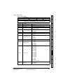
TxPDO mappings
Objects with the indices from 0x1A00 to 0x1BFF specify transmit PDO mappings. The
following mappings from DSP-402 are included as standard.
Mapping object index
Mapping object name
1
0x6041
statusword
2
0x6041
0x6061
statusword
modes_of_operation_display
3
0x6041
0x6064
statusword
position_actual_value
6
0x6041
0x6044
statusword
vl_velocity_actual_value
Mechanical
installation
PDO number
Introduction
Table 6.11 TxPDO mappings
Getting started
Table 6.12 TxPDO mapping 1
Transmit PDO mapping 1
Sub-index 0: Number of mapped objects
Access: RW
Range: 0 to (CF)
Size: 1 byte
1
Description:
The number of mapped objects in thie PDO
Unit: N/A
Protocols
Default:
Sub-index 1: 1st mapped object
Access: RW
Size: 4 bytes
Unit: N/A
0x60410010 - the DSP-402 status word (0x6041)
A mapping to an object with the following format:
Description:
Bits 0 to 7: Length of the mapped object in bits, e.g. a 32-bit parameter would
have a length of 32 or 0x20.
Bits 8 to 15: Sub-index of the mapped object.
Bits 16 to 31: Index of the mapped object.
Drive profile (DSP-402)
support
Default:
Range: 0 to
0xFFFFFFFF
Electrical
installation
The PDO mapping objects are defined below. Each mapping object has the maximum
number of sub-indices (each representing an object mapped to a PDO) defined in the
XML configuration file.
0x1A00
Safety
information
6.3.3
Advanced
features
Diagnostics
Quick
reference
Glossary of
terms
Index
SM-EtherCAT User Guide
Issue Number: 5
www.controltechniques.com
27
Table 6.13 TxPDO mapping 2
0x1A01
Transmit PDO mapping 2
Sub-index 0: Number of mapped objects
Access: RW
Range: 0 to (CF)
Size: 1 byte
Default:
2
Description:
The number of mapped objects in this PDO.
Unit: N/A
Sub-index 1: 1st mapped object
Range: 0 to
0xFFFFFFFF
Access: RW
Default:
Size: 4 bytes
Unit: N/A
0x60410010 - the DSP-402 status word (0x6041)
A mapping to an object with the following format:
Description:
Bits 0 to 7: Length of the mapped object in bits, e.g. a 32-bit parameter would
have a length of 32 or 0x20.
Bits 8 to 15: Sub-index of the mapped object.
Bits 16 to 31: Index of the mapped object.
Sub-index 2: 2nd mapped object
Range: 0 to
0xFFFFFFFF
Access: RW
Default:
Size: 4 bytes
Unit: N/A
0x60610008 - the DSP-402 modes of operation display object (0x6061)
A mapping to an object with the following format:
Description:
Bits 0 to 7: Length of the mapped object in bits, e.g. a 32-bit parameter would
have a length of 32 or 0x20.
Bits 8 to 15: Sub-index of the mapped object.
Bits 16 to 31: Index of the mapped object.
Table 6.14 Tx PDO mapping 3
0x1A02
Transmit PDO mapping 3
Sub-index 0: Number of mapped objects
Access: RW
Range: 0 to (CF)
Size: 1 byte
Default:
2
Description:
The number of mapped objects in this PDO.
Unit: N/A
Sub-index 1: 1st mapped object
Access: RW
Default:
Range: 0 to
0xFFFFFFFF
Size: 4 bytes
Unit: N/A
0x60410010 - the DSP-402 status word (0x6041)
A mapping to an object with the following format:
Description:
Bits 0 to 7: Length of the mapped object in bits, e.g. a 32-bit parameter would
have a length of 32 or 0x20.
Bits 8 to 15: Sub-index of the mapped object.
Bits 16 to 31: Index of the mapped object.
Sub-index 2: 2nd mapped object
Access: RW
Default:
Range: 0 to
0xFFFFFFFF
Size: 4 bytes
Unit: N/A
0x60640020 - the DSP-402 actual position (0x6064)
A mapping to an object with the following format:
Description:
28
Bits 0 to 7: Length of the mapped object in bits, e.g. a 32-bit parameter would
have a length of 32 or 0x20.
Bits 8 to 15: Sub-index of the mapped object.
Bits 16 to 31: Index of the mapped object.
www.controltechniques.com
SM-EtherCAT User Guide
Issue Number: 5
0x1A05
Safety
information
Table 6.15 TxPDO mapping 6
Transmit PDO mapping 6
Sub-index 0: Number of mapped objects
Access: RW
Range: 0 to (CF)
Size: 1 byte
2
Description:
The number of mapped objects in this PDO.
Unit: N/A
Introduction
Default:
Sub-index 1: 1st mapped object
Default:
Size: 4 bytes
Unit: N/A
Mechanical
installation
Range: 0 to
0xFFFFFFFF
Access: RW
0x60410010 - the DSP-402 status word (0x6041)
A mapping to an object with the following format:
Bits 0 to 7: Length of the mapped object in bits, e.g. a 32-bit parameter would
have a length of 32 or 0x20.
Bits 8 to 15: Sub-index of the mapped object.
Bits 16 to 31: Index of the mapped object.
Sub-index 2: 2nd mapped object
Default:
Size: 4 bytes
Getting started
Range: 0 to
0xFFFFFFFF
Access: RW
Unit: N/A
0x60440010 - the DSP-402 actual motor speed (0x6044).
A mapping to an object with the following format:
Bits 0 to 7: Length of the mapped object in bits, e.g. a 32-bit parameter would
have a length of 32 or 0x20.
Bits 8 to 15: Sub-index of the mapped object.
Bits 16 to 31: Index of the mapped object.
Drive profile (DSP-402)
support
Table 6.16 TxPDO mapping 22
0x1A15
Transmit PDO mapping 22
Sub-index 0: Number of mapped objects
Access: RW
Range: 0 to (CF)
Size: 1 byte
Default:
0
Description:
The number of mapped objects in thie PDO
Unit: N/A
Range: 0 to
0xFFFFFFFF
Default:
Size: 4 bytes
Advanced
features
Sub-indices 1 to 255: 1st to 255th mapped objects in this PDO.
Access: RW
Unit: N/A
0
Quick
reference
Bits 0 to 7: Length of the mapped object in bits, e.g. a 32-bit parameter would
have a length of 32 or 0x20.
Bits 8 to 15: Sub-index of the mapped object.
Bits 16 to 31: Index of the mapped object.
Diagnostics
A mapping to an object with the following format:
Description:
Protocols
Description:
Electrical
installation
Description:
Glossary of
terms
Index
SM-EtherCAT User Guide
Issue Number: 5
www.controltechniques.com
29
6.3.4
Sync manager configuration
The sync managers are the EtherCAT means for setting access attributes for different
areas of memory and triggering or notifying the application when the memory is
accessed. The following objects specify how the sync managers (and thus
corresponding memory areas) are utilized by the CoE protocol.
Table 6.17 Sync manager communication type object
0x1C00
Sync manager communication type
Sub-index 0 - number of sync manager channels used
Access: RO
Range: N/A
Size: 1 byte
Unit: N/A
Default:
4
Description:
The number of sync manager protocols used by the CoE protocol.
Sub-index 1 - Usage of sync manager 0
Access: RO
Range: N/A
Size: 1 byte
Unit: N/A
Default:
1
Description:
Sync manager 0 is used by CoE as the mailbox receive channel (master to
slave).
Sub-index 2 - Usage of sync manager 1
Access: RO
Range: N/A
Size: 1 byte
Unit: N/A
Default:
2
Description:
Sync manager 1 is used by CoE as the mailbox send channel (slave to master).
Sub-index 3 - Usage of sync manager 2
Access: RO
Range: N/A
Size: 1 byte
Unit: N/A
Default:
3
Description:
Sync manager 2 is used by CoE as the process data output (RxPDOx - master to
slave).
Sub-index 4 - Usage of sync manager 3
Access: RO
Range: N/A
Size: 1 byte
Unit: N/A
Default:
4
Description:
Sync manager 3 is used by CoE as the process data input (TxPDOs - slave to
master).
Table 6.18 Sync manager 0 PDO assignment object
0x1C10
Sync manager 0 PDO assignment
Sub-index 0
Access: RO
Range: N/A
Size: 1 byte
Unit: N/A
Default:
0
Description:
Number of assigned PDOs. The mailbox received sync manager can never have
PDOs assigned to it.
Table 6.19 Sync manager 1 PDO assignment object
0x1C11
Sync manager 1 PDO assignment
Sub-index 0
Access: RO
30
Range: N/A
Size: 1 byte
Unit: N/A
Default:
0
Description:
Number of assigned PDOs. The mailbox send sync manager can never have
PDOs assigned to it.
www.controltechniques.com
SM-EtherCAT User Guide
Issue Number: 5
0x1C12
Safety
information
Table 6.20 Sync manager 2 PDO assignment object
Sync manager 2 PDO assignment
Sub-index 0
Access: RW
Range: 0 to 255
Size: 1 byte
Unit: N/A
1
Description:
The number of RxPDOs assigned to this sync manager (used for process data
output).
Sub-indices 1 to (sub-index 0)
Size: 2 bytes
Unit: N/A
Default:
0x1605
Description:
The object index of a RxPDO to assign to this sync manager. By default this is
assigned to RxPDO mapping 6 (vl_target_velocity and controlword).
Electrical
installation
Table 6.21 Sync manager 3 PDO assignment object
0x1C13
Mechanical
installation
Range: 0x1600 to
0x17FF
Access: RW
Introduction
Default:
Sync manager 3 PDO assignment
Sub-index 0
Range: 0 to 255
Size: 1 byte
Unit: N/A
Default:
1
Description:
The number of TxPDOs assigned to this sync manager (used for process data
input).
Range: 0x1A00 to
0x1BFF
Access: RW
Unit: N/A
Default:
0x1A05
Description:
The object index of a TxPDO to assign to this sync manager. By default this is
assigned to TxPDO mapping 6 (vl_velocity_actual_value and statusword).
Feedback encoder source
Table 6.22 Feedback encoder source
0x2802
Feedback encoder source
Drive profile (DSP-402)
support
6.3.5
Size: 2 bytes
Protocols
Sub-indices 1 to (sub-index 0)
Getting started
Access: RW
Sub-index 0
Range: 0 to 3
Size: 1 byte
Advanced
features
Access: RW
Unit: N/A
Default:
0
Description:
This object specifies the source position for position controller feedback.
Diagnostics
0 = Use drive as the feedback source
1 = Use the encoder module in slot 1 as the encoder source
2 = Use the encoder module in slot 2 as the encoder source
3 = Use the encoder module in slot 3 as the encoder source
Quick
reference
Glossary of
terms
Index
SM-EtherCAT User Guide
Issue Number: 5
www.controltechniques.com
31
6.4
Ethernet over EtherCAT (EoE)
This protocol allows standard Ethernet messages and protocols to be tunnelled through
the EtherCAT network. This provides users with the possibility of connecting to the
Control Techniques PC Tools (SyPT Pro, SyPTLite, CTSoft, CTScope and Winflasher)
along the same connection currently being used for SM-EtherCAT communications.
NOTE
6.4.1
For help configuring this protocol with the Control Techniques PC Tools, please refer to
Knowledge Base document COMMS046 on CTSupport titled Connecting to the Control
Techniques’ PC Tools using the SM-EtherCAT module and EoE (Ethernet over
EtherCAT).
EoE IP address
The SM-EtherCAT EoE IP address is defined in the EtherCAT Master and is displayed
in the module parameters as shown in Figure 6-1.
Figure 6-1 EoE IP address format
SM-EtherCAT EoE IP address
Wip Xip Yip Zip
Pr MM.10
Pr MM.11
Pr MM.12
Pr MM.13
Table 6.23 EoE - IP address Wip
EoE - IP address Wip
Pr MM.10
Default
0
Range
0 to 255
Access
RW
This is the most significant octet of the SM-EtherCAT EoE IP address.
Table 6.24 EoE - IP address Xip
EoE - IP address Xip
Pr MM.11
Default
0
Range
0 to 255
Access
RW
This is the second most significant octet of the SM-EtherCAT EoE IP address.
Table 6.25 EoE - IP address Yip
EoE - IP address Yip
Default
Pr MM.12
0
Range
0 to 255
Access
RW
This is the third most significant octet of the SM-EtherCAT EoE IP address.
32
www.controltechniques.com
SM-EtherCAT User Guide
Issue Number: 5
Safety
information
Table 6.26 EoE - IP address Zip
EoE - IP address Zip
Default
Range
0 to 255
Access
RW
Introduction
Pr MM.13
0
6.4.2
Mechanical
installation
This is the least significant octet of the SM-EtherCAT EoE IP address.
EoE Subnet mask
The SM-EtherCAT EoE Subnet mask is defined in the EtherCAT Master and is
displayed in the module parameters as shown in Figure 6-2.
W
subnet
Pr MM.14
X
subnet
Pr MM.15
Y
subnet
Pr MM.16
Z
Getting started
SM-EtherCAT EoE Subnet mask
Electrical
installation
Figure 6-2 EoE Subnet mask format
subnet
Pr MM.17
Protocols
Table 6.27 EoE - Subnet mask Wsubnet
EoE - Subnet Mask Wsubnet
0
Range
0 to 255
Access
RW
Drive profile (DSP-402)
support
Pr MM.14
Default
This is the most significant octet of the SM-EtherCAT EoE Subnet mask.
Table 6.28 EoE - Subnet mask Xsubnet
Advanced
features
EoE - Subnet Mask Xsubnet
Default
Range
0 to 255
Access
RW
Diagnostics
Pr MM.15
0
This is the second most significant octet of the SM-EtherCAT EoE Subnet mask.
Quick
reference
Table 6.29 EoE - Subnet mask Ysubnet
EoE - Subnet Mask Ysubnet
0
Range
0 to 255
Access
RW
Glossary of
terms
Pr MM.16
Default
This is the third most significant octet of the SM-EtherCAT EoE Subnet mask.
Index
SM-EtherCAT User Guide
Issue Number: 5
www.controltechniques.com
33
Table 6.30 EoE - Subnet mask Zsubnet
EoE - Subnet Mask Zsubnet
Default
Pr MM.17
0
Range
0 to 255
Access
RW
This is the least significant octet of the SM-EtherCAT EoE Subnet mask.
6.4.3
EoE Default gateway
The SM-EtherCAT EoE Default gateway is defined in the EtherCAT Master and is
displayed in the module parameters as shown in Figure 6-3.
Figure 6-3 EoE Default gateway
SM-EtherCAT EoE Default gateway
W
gateway
Pr MM.18
NOTE
X
gateway
Pr MM.19
Y Z
gateway
Pr MM.20
gateway
Pr MM.21
The default gateway is a routing device that allows a host to reach other devices that
are not on the same subnet. The default gateway must be on the same subnet as the
host that is trying to use it.
Table 6.31 EoE - Default gateway Wgateway
EoE - Default gateway Wgateway
Pr MM.18
Default
0
Range
0 to 255
Access
RW
This is the most significant octet of the SM-EtherCAT EoE Default gateway.
Table 6.32 Default gateway Xgateway
EoE - Default gateway Xgateway
Pr MM.19
Default
0
Range
0 to 255
Access
RW
This is the second most significant octet of the SM-EtherCAT EoE Default gateway.
Table 6.33 Default gateway Ygateway
EoE - Default gateway Ygateway
Pr MM.20
Default
0
Range
0 to 255
Access
RW
This is the third most significant octet of the SM-EtherCAT EoE Default gateway.
34
www.controltechniques.com
SM-EtherCAT User Guide
Issue Number: 5
Safety
information
Table 6.34 Default gateway Zgateway
EoE - Default gateway Zgateway
Default
Range
0 to 255
Access
RW
Introduction
Pr MM.21
0
NOTE
SM-EtherCAT reduce serial interface priority
Getting started
Table 6.35 Reduce Drive serial interface priority
Reduce Drive serial interface priority
Default
OFF - ON
Access
RW
Protocols
Pr MM.37
OFF
Range
Pr MM.37 = OFF (default):
Pr MM.37 = ON:
NOTE
Pr MM.37 only needs to be considered when used with a Unidrive SP, Digitax ST,
Mentor MP of Affinity. It has no use when used with a Commander SK.
SM-EtherCAT User Guide
Issue Number: 5
www.controltechniques.com
Index
Pr MM.37 must be set to ON to achieve EoE communications.
Glossary of
terms
1. The drives serial interface will only be able to handle messages that are 32 bytes or
less. A Remote LCD keypad would continue to work, although SM-Application
parameters would not be visible. If a message is received that is too long for the
drive to handle, no reply will be sent.
2. Any LCD keypad fitted (not remotely mounted) to the drive will stop working.
Quick
reference
The SM-EtherCAT module will request that the drive permits it to become the primary
communication interface. If the drive is able to transfer control then the following
restrictions will be imposed:
Diagnostics
1. Those that access Drive parameters
2. Those that access SM-Applications parameters.
Advanced
features
It will not be possible to forward on messages that are intended for either the drive or
another option module. The SM-EtherCAT module will be able to handle two types of
messages:
Drive profile (DSP-402)
support
It is not possible for the both the Drive and the SM-EtherCAT module to support all of
the available serial communication protocols simultaneously. This means that the user
must decide if they wish the drive to provide the primary communication interface via its
serial RJ45 connector, or the SM-EtherCAT module. In the default state the primary
interface will be provided by the drive.
NOTE
Electrical
installation
6.4.4
Although parameters Pr MM.10 - Pr MM.21 have RW access, changing them via the
parameters will have no affect to the EoE settings. The EoE configuration for the SMEtherCAT module can only be done with an EtherCAT master which supports the EoE
protocol (e.g. TwinCAT). The settings for Pr MM.10 - Pr MM.21 will need to be set by
the Master and these parameters are for display purposes only.
Mechanical
installation
This is the least significant octet of the SM-EtherCAT EoE Default gateway.
35
7
Drive profile (DSP-402) support
SM-EtherCAT supports the following modes of the DSP-402 profile:
7.1
•
Cyclic sync position mode
•
Interpolated position mode
•
vl velocity mode
•
Profile torque mode
•
Homing mode
0x6040 Controlword
This provides the primary method of controlling the behavior of the drive e.g. enabling,
disabling, resetting, etc. Table 7.1 describes the format of the control word. The
individual bits are used in combinations (see Table 7.2) to sequence the drive through
the state machine described in Figure 7-1.
Table 7.1 Controlword
0x6040
Controlword
Access: RW
Range: 0 to 65535
Default:
Description:
15
14
Size: Unsigned 16
Unit: N/A
N/A
Provides the primary method of controlling the behavior of the drive.
13
Reserved
12
11
10
9
8
7
ila
r
oms
h
fr
6
5
oms
4
3
2
1
0
hos
eo
qs
ev
so
LEGEND: ms = manufacturer-specific; r = reserved; oms = operation mode specific; h = halt;
fr = fault reset; hos = homing operation start; eo = enable operation; qs = quick stop; ev =
enable voltage; so = switch on
Table 7.2 Command coding
Bits of the controlword
Command
Bit 7
Bit 3
Bit 2
Bit 1
Shutdown
0
X
1
1
0
Switch on
0
0
1
1
1
Bit 0
Switch on + enable
operation
0
1
1
1
1
Disable voltage
0
X
X
0
X
Quick stop
0
X
0
1
X
Disable operation
0
0
1
1
1
Enable operation
0
1
1
1
1
X
X
X
X
Fault reset
NOTE: Automatic transition to Enable operation state after executing SWITCHED ON state
functionality.
36
www.controltechniques.com
SM-EtherCAT User Guide
Issue Number: 5
0x6041 Statusword
This provides feedback about the current operating state of the drive. Table 7.4
describes the format of the status word and illustrates how the individual statusword bits
are combined to represent the current state of the drive.
Introduction
Table 7.3 Statusword
0x6041
Statusword
Access: RW
Range: 0 to 65535
Size: Unsigned 16
Unit: N/A
N/A
Description:
This provides feedback about the current operating state of the drive.
Table 7.4 Statusword bit functions
15
14
13
12
11
10
9
8
7
6
5
4
3
2
1
0
ha
ila
tr
rm
ms
w
sod
qs
ve
f
oe
so
rtso
Table 7.5 State coding
Statusword
xxxx xxxx x1xx 0000b
Switch on disabled
xxxx xxxx x01x 0001b
Ready to switch on
xxxx xxxx x01x 0011b
Switched on
xxxx xxxx x01x 0111b
Operation enabled
xxxx xxxx x00x 0111b
Quick stop active
xxxx xxxx x0xx 1111b
Fault reaction active
xxxx xxxx x0xx 1000b
Fault
Drive profile (DSP-402)
support
Common profile features
Sequencing control
Advanced
features
7.3.1
Not ready to switch on
Protocols
7.3
State
xxxx xxxx x0xx 0000b
These are the supported objects used to control the drive:
Table 7.6 Sequencing control supported objects
Name
controlword
shutdown_option_code
0x605C
disable_operation_option_code
0x605A
quick_stop_option_code
0x605D
halt_option_code
0x605E
fault_reaction_option_code
0x6060
modes_of_operation
0x6061
modes_of_operation_display
0x6085
quick_stop_deceleration
Glossary of
terms
statusword
Quick
reference
0x6041
0x605B
Diagnostics
Index
0x6040
Getting started
LEGEND: ms = manufacturer-specific; ha = homing attained; oms = operation mode
specific; ila = internal limit active; tr = target reached; rm = remote; w = warning; sod =
switch on disabled; qs = quick stop; ve = voltage enabled; f = fault; oe = operation
enabled; so = switched on; rtso = ready to switch on
Electrical
installation
ms
Mechanical
installation
Default:
Safety
information
7.2
Index
SM-EtherCAT User Guide
Issue Number: 5
www.controltechniques.com
37
The behavior of the sequencing control is shown in Figure 7-1 CoE state machine
diagram . This state machine indicates how the drive will be controlled. For clarity the
Statusword is abbreviated to ‘SW’ in the diagram.
When in the ‘QUICK STOP ACTIVE’ state, the currently selected mode of operation
indicates how a quick stop function should be handled. When the drive is stopped, and
the Quick stop option code doesn’t indicate that the state should remain at ‘QUICK
STOP ACTIVE’, the state will move to ‘SWITCH ON DISABLED’.
When in the ‘OPERATION ENABLED’ or ‘QUICK STOP ACTIVE’ states it is not
possible to change the mode_of_operation object. This is to ensure that the motor is
stopped before changing the operation mode.
The SM-EtherCAT master device must be in the operational state before the state
machine can move from the ‘SWITCH ON DISABLED’ state to the ‘READY TO
SWITCH ON’ state. If the master leaves the operational state while the state machine is
in the ‘SWITCH ON’, ‘OPERATION ENABLE’ , ‘QUICK STOP ACTIVE’ or ‘READY TO
SWITCH ON’ state then the option will transition to the ‘SWITCH ON DISABLED’ state.
This implies that the drive will be inhibited and the motor will coast.
38
www.controltechniques.com
SM-EtherCAT User Guide
Issue Number: 5
Power disabled
Fault
13
Any drive
trip
0
Drive not
tripped Pr 10.01 = 1
Fault reaction
complete
Electrical
installation
NOT READY TO
SWITCH ON
1
FAULT
15
Getting started
Fault reset
Pr 10.02 = 0
Protocols
SWITCH ON
DISABLED
2
Shutdown
Quick stop
Drive profile (DSP-402)
support
7
READY TO
SWITCH ON
3
Switch On
SWITCHED ON
Advanced
features
Power enabled
Shutdown
6
Disable
10 voltage
8
Enable 11
operation
12
QUICK STOP
ACTIVE
SM-EtherCAT User Guide
Issue Number: 5
www.controltechniques.com
39
Index
On the Digitax ST, Unidrive SP, Affinity and Mentor MP with the default drive
parameters the 'Switched on' state will correspond to a drive status of 'STOP'. If the
STOP state is not acceptable for any SM-EtherCAT applications that do not use the
menu 12 brake controller, Pr 6.08 will have to be set to OFF. With Pr 6.08 set to OFF
the 'Switched on' state will now correspond to a drive status of 'Rdy'.
Glossary of
terms
NOTE
9
16 Quick stop
Quick
reference
Disable
voltage
Disable
voltage
Disable
operation
5
OPERATION
ENABLE
Diagnostics
4
Enable
operation
Shutdown
Mechanical
installation
FAULT REACTION
ACTIVE
14
START
Introduction
Any drive
trip
Safety
information
Figure 7-1 CoE state machine diagram
Table 7.7 CoE state machine transition and events
Transition
40
Event(s)
Action(s)
0
Automatic transition after power-on or
reset application
Drive device self-test and/or self
Initialization shall be performed
1
Automatic transition
Communication shall be activated
2
Shutdown command from control device
or local signal
None
3
Switch on command received from control Power section shall be switched on if not
device or local signal
already switched on
4
Enable operation command received from Drive function shall be enabled and clear
control device or local signal
all internal set-points
5
Disable operation command received from
Drive function shall be disabled
control device or local signal
6
The high-power shall be switched off
Shutdown command received from control immediately, and the motor shall be free to
device or local signal
rotate if not braked; additional action
depends on the shutdown option code
7
Quick stop or disable voltage command
from control device or local signal
None
8
Shutdown command from control device
or local signal
The high-power shall be switched off
immediately if possible, and the motor
shall be free to rotate if not braked
9
Disable voltage command from control
device or local signal
The high-power shall be switched off
immediately if possible, and the motor
shall be free to rotate if not braked
10
Disable voltage or quick stop command
from control device or local signal
The high-power shall be switched off
immediately if possible, and the motor
shall be free to rotate if not braked
11
Quick stop command from control device
or local signal
The quick stop function shall be started
12
Automatic transition when the quick stop
function is completed and quick stop
option code 1, 2, 3 or 4 disable voltage
The power section shall be switched off
command received from control device
(dependant on the quick stop option code)
13
Fault signal
The configure fault reaction function shall
be executed
14
Automatic transition
The drive function shall be disabled; the
high-power may be switched off
15
Fault reset command from control device
or local signal
A reset of the fault condition is carried out,
if no fault exists currently on the drive
device; after leaving the Fault state, the
Fault reset bit in the controlword shall be
cleared by the control device
16
Enable operation command from control
device, if the quick stop option code is 5,
6, 7 or 8
The drive function shall be enabled
www.controltechniques.com
SM-EtherCAT User Guide
Issue Number: 5
Pr 6.42 to 0
•
Pr 6.43 to On (1)
•
Pr 3.22 to 0 (where present)
•
Pr 3.23 to On (1) (where present)
•
Pr 3.13 to OFF (0) (In open-loop operating modes)
•
Pr 2.10 to 1
•
Pr 2.20 to 1
•
Pr 2.02 to On (1)
•
Pr 1.04 to 0
•
Pr 1.21 to 0
•
Pr 1.38 to 0
•
Pr 1.08 to OFF (0)
•
Pr 1.10 to On (1)
•
Pr 1.09 to OFF (0)
•
Pr 1.15 to 1
•
Pr 1.14 to 3
Introduction
•
Mechanical
installation
Electrical
installation
Getting started
This object indicates what action is performed when the quick stop function is executed.
The slow down ramp is the deceleration value of the used mode of operations.
Table 7.8 Quick_stop_option_code
Quick_stop_option_code
Access: RW
Range: 0 to 6
Size: Unsigned 16
Unit: N/A
2
Description:
Specifies what action is performed in the event of a quick stop function. See
Table 7.7 CoE state machine transition and events on page 40 for more
information.
Table 7.9 Quick stop value definitions
Value
Diagnostics
Default:
Advanced
features
0x605A
Drive profile (DSP-402)
support
0x605A Quick stop option code
Protocols
These values are set once and not continuously forced. They are not reset when leaving
the Operational state. In addition, the option starts to write parameters implicitly mapped
by the CoE profiles, when moving to the Operational state.
7.3.2
Safety
information
When the SM-EtherCAT module transitions from the EtherCAT Safe-operational state to
the EtherCAT Operational state, a number of drive parameters are set to allow the CoE
profiles to control the drive and motor. These parameters are set in the following order:
Definition
Disable drive function
1
Slow down on slow down ramp and transit into Switch on disabled
Slow down on quick stop ramp and transit into Switch on disabled
5
Slow down on slow down ramp and stay in Quick stop active
6
Slow down on quick stop ramp and stay in Quick stop active
Glossary of
terms
2
Quick
reference
0
Index
SM-EtherCAT User Guide
Issue Number: 5
www.controltechniques.com
41
7.3.3
0x605B Shutdown_option_code
This object is used to control what action is performed if there is a transition from the
Operation Enabled state to the Ready To Switch On state.
Table 7.10 Shutdown_option_code
0x605B
Shutdown_option_code
Access: RW
Range: 0 to 1
Size: Unsigned 16
Unit: N/A
Default:
N/A
Description:
Used to control what action is performed if there is a transition from the Operation
Enabled state to the Ready To Switch On state.
Table 7.11 Shutdown_option_code values
Value
7.3.4
Definition
0
Disable drive function (switch off the drive power stage)
1
Slow down with slow down ramp; disable the drive function
0x605C Disable_operation_option_code
Disable drive function (switch off the drive power stage).
This object is used to control what action is performed if there is a transition from the
‘Operation Enabled’ state to the ‘Switched On’ state.
Table 7.12 Disabled_operation_option_code
0x605C
Disable_operation_option_code
Access: RW
Range: 0 to 1
Size: Unsigned 16
Unit: N/A
Default:
N/A
Description:
This object is used to control what action is performed if there is a transition from
the Operation Enabled state to the Switched On state.
Table 7.13 Disable_operation_option_code values
Value
7.3.5
Definition
0
Disable drive function (switch off the drive power stage)
1
Slow down with slow down ramp; disable the drive function
0x605E Fault_reaction_option_code
This object is used to control what action is performed when a fault is detected. This
object is ignored if the drive is tripped.
Table 7.14 Fault_reaction_option_code
0x605E
Fault_reaction_option_code
Access: RW
Range: 0 to 2
Size: Unsigned 16
Unit: N/A
Default:
N/A
Description:
This object is used to control what action is performed when a fault is detected.
Table 7.15 Fault_reaction_option_code values
Value
42
Definition
0
Disable drive function, motor is free to rotate
1
Slow down on slow down ramp
2
Slow down on quick stop ramp
www.controltechniques.com
SM-EtherCAT User Guide
Issue Number: 5
0x6060 Modes_of_operation
Safety
information
7.3.6
This object is used to request a change in the mode of operation.
Table 7.16 Modes_of_operation
Modes_of_operation
Access: RW
Range: 0 to 8
Size: Unsigned 8
Introduction
0x6060
Unit: N/A
Default:
2
Description:
This object is used to request a change in the mode of operation.
Mechanical
installation
Table 7.17 Modes_of_operation values
Value
2
vl velocity mode
4
Profile torque mode
6
Homing mode
7
Interpolated position mode
8
Cyclic sync position mode
Getting started
No mode change
Electrical
installation
7.3.7
Definition
0
0x6061 Modes_of_operation_display
This read only object indicates the active mode of operation.
0x6061
Protocols
Table 7.18 Modes_of_operation_display
Modes_of_operation_display
Access: RO
Range: 0 to 8
Size: Unsigned 8
N/A
Description:
Used to provide the active mode of operation.
Unit: N/A
Drive profile (DSP-402)
support
Default:
Table 7.19 Modes_of_operation_display values
Value
No mode change
2
vl velocity mode
4
Profile torque mode
6
Homing mode
7
Interpolated position mode
8
Cyclic sync position mode
Advanced
features
Diagnostics
7.3.8
Definition
0
0x6084 Profile decleration
Table 7.20 Profile decleration
0x6084
Profile deceleration
Size: Unsigned 32
65536
Description:
Provides the deceleration ramp for the positioning modes
Unit: N/A
Glossary of
terms
Default:
Quick
reference
Range:0 to
0xFFFFFFFF
Access: RW
Index
SM-EtherCAT User Guide
Issue Number: 5
www.controltechniques.com
43
7.3.9
0x6085 Quick_stop_deceleration
This object is used to configure the deceleration rate used to stop the motor when the
quick stop function is activated and the quick stop code object (0x605A) is set to 2 or 6.
The quick stop deceleration is also used if the fault reaction code object (0x605E) is 2.
The value is given in user-defined acceleration units.
Table 7.21 Quick_stop_deceleration
0x6085
Quick_stop_deceleration
Sub-index 0
Range:0 to
0xFFFFFFFF
Access: RW
Size: Unsigned 32
Default:
2
Description:
Quick stop function for the positioning related modes.
Unit: N/A
7.3.10 Profile units
The SM-EtherCAT implementation provides a means to convert profile units into
position controller and drive units. All scaling values are standard profile objects. The
following objects are supported:
Table 7.22 Supported profile units
Index
Name
0x608F
position_encoder_resolution
0x6091
gear_ratio
0x6092
feed_constant
For positions, the scaling control includes a feed constant, a gear ratio and an encoder
revolution. These values are combined by the implementation into a simple scaling
numerator and denominator. It is possible to change these values non-cyclically (i.e.
using SDOs), in which case the scaling numerator and denominator and any position
limit values are recalculated in the background. It is not, however, possible to change
these values cyclically (i.e. by mapping PDOs to them).
For velocities, in addition to the position constants described above, these values are
combined into a simple numerator and denominator to scale velocities to internal
velocity units. This scaling also properly handles remainders (i.e. when used on a
reference or feedback, accumulate the remainder and add it to subsequent velocity
values, and when used with a limit, round up or down). It is possible to change these
values non-cyclically (i.e. using SDOs), in which case the scaling numerator and
denominator is recalculated in the background. It is also necessary to re-scale velocity
limit values with the new factor. It is not possible to change these values cyclically (i.e.
by mapping PDOs to them).
44
www.controltechniques.com
SM-EtherCAT User Guide
Issue Number: 5
This read only object indicates the configured encoder increments per number of motor
revolutions. The information is read from the drive's encoder configuration.
0x608F
Introduction
Table 7.23 Position_encoder_resolution
Position_encoder_resolution
Sub-index 0
Access: RO
Range: N/A
Size: Unsigned 8
Unit: N/A
Range: 0 to
0xFFFFFFFF
Size: Unsigned 32
Unit: N/A
Size: Unsigned 32
Unit: N/A
Mechanical
installation
Default:
2
Description:
Sub-index 1
Default:
1
Description:
Encoder increments
Electrical
installation
Access: RO
Range: 0 to
0xFFFFFFFF
Default:
1
Description:
Motor revolutions
Getting started
Sub-index 2
Access: RO
gear ratio = motor shaft revolutions / driving shaft revolutions
Table 7.24 Gear_ratio
Gear_ratio
Sub-index 0
Access: RO
Range: N/A
Size: Unsigned 8
Unit: N/A
Range: 0 to
0xFFFFFFFF
Size: Unsigned 32
Unit: N/A
Size: Unsigned 32
Unit: N/A
Advanced
features
Default:
2
Description:
Sub-index 1
Default:
1
Description:
Motor revolutions
Diagnostics
Access: RW
Range: 0 to
0xFFFFFFFF
1
Description:
Shaft revolutions
Glossary of
terms
Default:
Quick
reference
Sub-index 2
Access: RW
Drive profile (DSP-402)
support
This object is used to apply scaling. When configured, appropriate user units can be
used to control the position of the shaft beyond a gearbox. The gear ratio is calculated
using the following formula:
Protocols
7.3.12 0x6091 Gear_ratio
0x6091
Safety
information
7.3.11 0x608F Position_encoder_resolution
Index
SM-EtherCAT User Guide
Issue Number: 5
www.controltechniques.com
45
7.3.13 0x6092 Feed_constant
This is used to configure a feed constant. This is the measurement distance per one
revolution of the output shaft of the gearbox. The feed constant is calculated using the
following formula:
feed constant = feed / driving shaft revolutions
Table 7.25 Feed_constant
0x6092
Feed_constant
Sub-index 0
Access: RO
Default:
Range: N/A
Size: Unsigned 8
Unit: N/A
Range: 0 to
0xFFFFFFFF
Size: Unsigned 32
Unit: N/A
Range: 0 to
0xFFFFFFFF
Size: Unsigned 32
Unit: N/A
2
Description:
Sub-index 1
Access: RW
Default:
1
Description:
Feed
Sub-index 2
Access: RW
Default:
1
Description:
Shaft revolutions
7.3.14 Basic position control
Basic position control is supported on the Unidrive SP in servo mode, closed-loop
vector mode and RFC mode. It works on the Digitax ST and Mentor MP but is not
supported in open-loop or regen mode on any of the drives. It is also not available on
Commander SK or Affinity. The position control described here is used under the
interpolated position mode of operation. Table 7.26 lists the objects that are supported:
Table 7.26 Basic position control supported objects
Index
Name
0x6062
position_demand_value
0x6064
position_actual_value
0x6065
following_error_window
0x6067
position_window
0x6080
max motor speed
0x60F4
following_error_actual_value
0x60FB
position_control_parameter_set
7.3.15 0x6062 Position_demand_value
This read only object is used to provide the currently demanded position value. The
value is given in user defined position units.
Table 7.27 Position_demand_value
0x6062
Position_demand_value
Range: 0 to
0xFFFFFFFF
Access: RO
46
Size: signed 32
Unit: N/A
Default:
N/A
Description:
Used to provide the currently demanded position value.
www.controltechniques.com
SM-EtherCAT User Guide
Issue Number: 5
This read only object provides the actual value of the position feedback device. The
value is given in internal units.
Table 7.28 Position_actual_value
Introduction
0x6064
Position_actual_value
Range: 0 to
0xFFFFFFFF
Access: RO
Size: signed 32
Safety
information
7.3.16 0x6064 Position_actual_value
Unit: N/A
N/A
Description:
This read only object provides the actual value of the position feedback device.
The value is given in internal units.
Mechanical
installation
Default:
7.3.17 0x6080 Max motor speed
Description:
Max motor speed
Range: 0 to 0xFFFFFFFF Size: Unsigned 32
Unit: rpm
3000
This object indicates the configured maximum allowed speed for the motor in either
direction. It is used to protect the motor and changing the value of this object will
also change Pr 1.06. The value is given in rotations per minute (rpm).
This read only object provides the actual value of the following error. The value is given
in user-defined position units.
0x60F4
Drive profile (DSP-402)
support
Table 7.30 Following_error actual_value
Following_error actual_value
Range: 0 to
0xFFFFFFFF
Access: RO
Size: signed 32
Unit: N/A
Default:
N/A
Description:
This read only object provides the actual value of the following error.
Advanced
features
7.3.19 0x60FB Position_control_parameter_set object
Table 7.31 Position_control_parameter_set object
0x60FB
Position_control_parameter_set
Range: N/A
Size: Unsigned 8
Default:
2
Description:
The number of control loop parameters.
Diagnostics
Sub-index 0
Access: RO
Unit: N/A
Size: Unsigned 16
2500
Description:
The position controller proportional gain.
Unit: 0.01 rad/s/rad
Unit: 1 / 1000
Glossary of
terms
Range: 0 to 65535
Default:
Quick
reference
Sub-index 1
Access: RW
Sub-index 2
Access: RW
Range: 0 to 65535
Size: Unsigned 16
Default:
1000 (i.e. a gain of 1)
Description:
The position controller speed feed forward gain.
Protocols
7.3.18 0x60F4 Following_error_actual_value
Getting started
0x6080
Sub-index 0
Access: RW
Default:
Electrical
installation
Table 7.29 Max motor speed
Index
SM-EtherCAT User Guide
Issue Number: 5
www.controltechniques.com
47
The APC position controller kernel is used by the basic internal position control.
The position_demand_value object contains the value supplied by either the
interpolated position mode or the profile position mode (in user units). It is updated
every control loop cycle. This object can be mapped as cyclic data.
7.4
Interpolated position mode
Interpolated position mode operates on the Unidrive SP in servo mode, closed-loop
vector mode and RFC mode. This mode also operates on the Digitax ST and Mentor
MP. Table 7.32 lists the objects that are supported:
Table 7.32 Supported Interpolated position mode objects
Index
NOTE
7.4.1
Name
0x60C0
interpolation_submode_select
0x60C1
interpolation_data_record
0x60C2
interpolation_time_period
When using one of the DSP-402 positioning modes, Distributed Clocks must be
enabled. Failure to do so may result in the SM-EtherCAT module going into the SAFEOPERATIONAL state (Pr MM.04 = 4).
0x60C0 Interpolation_sub-mode_select
Table 7.33 0x60C0 Interpolation_sub-mode_select
0x60C0
Interpolation_sub-mode_select
Access: RW
7.4.2
Range: 0
Size: Signed 16
Unit: N/A
Default:
0 (Linear interpolation)
Description:
Specifies the interpolation type. At present the only supported Interpolation SubMode is ‘Linear Interpolation’.
0x60C1 Interpolation_data_record
This object is used to specify the target position. Linear interpolation is used to generate
position demand values every 250µs. The position is specified in user-defined position
units. The value is written into sub-index 1.
Table 7.34 0x60C1 Interpolation_data_record
0x60C1
Interpolation_data_record
Sub-index 0
Access: RO
Range: N/A
Size: Unsigned 8
Default:
1
Description:
This object is used to specify the target position.
Unit: N/A
Sub-index 1
Range: 0 to
0xFFFFFFFF
Access: RW
48
Default:
N/A
Description:
The set-point.
Size: Unsigned 32
www.controltechniques.com
Unit: N/A
SM-EtherCAT User Guide
Issue Number: 5
0x60C2 Interpolation_time_period
Safety
information
7.4.3
Table 7.35 Interpolation_time_period
0x60C2
Interpolation_time_period
Sub-index 0
Range: N/A
Size: Unsigned 8
Default:
2
Description:
The number of the last sub-index in this object.
Introduction
Access: RO
Unit: N/A
Access: RW
Range: 0 to 255
Size: Unsigned 8
Unit: (sub-index 2)
250 (units are dependant on the value in sub-index 2)
Description:
The number of time units between interpolator re-starts. A time unit is defined by
sub-index 2. The interpolator time period value is checked to ensure that it is
valid. Valid values are 250µs, 500µs or any multiple of 1ms. An attempt to write
other values results in an SDO Abort code.
Sub-index 2
Access: RW
Range: -6 to 0
Size: Signed 8
Unit: N/A
-6 (a time unit of 1µs)
Description:
This specifies the time unit for the interpolation time period. Sub-index 2
specifies the unit exponent. The time unit, therefore, is 10(sub-index 2). The
range of values allows for the shortest time unit to be 1µs, and the longest to be
1s.
Description
1 second
-1
0.1 of a second
-2
0.01 of a second
-3
0.001 of a second
0.0001 of a second
-5
0.00001 of a second
-6
0.000001 of a second
Glossary of
terms
The input buffer has a maximum size of 1 data record, and a data record contains one
position in profile-defined units. The buffer is a FIFO buffer. On each interpolator time
period, a value is read from this buffer. The correct number of data points for a specific
interpolation mode are stored internally. When a new position command is loaded in, the
oldest position command in the data set is discarded.
Quick
reference
The time period is checked to ensure that it is an integer multiple of the control loop
cycle time. Only linear interpolation is currently supported, this type inserts a delay of
one interpolation time period.
Diagnostics
-4
Advanced
features
0
Drive profile (DSP-402)
support
Table 7.36 Interpolation time period units
Protocols
The implementation of interpolated position mode allows synchronous operation only,
where a fixed, common interpolation interval is defined. The time specified must always
be an integer multiple of the control loop cycle time. The time period index has a
minimum value of -6 (i.e. the smallest time unit will be microseconds), see Table 7.36 for
more information.
Getting started
Default:
Value in 0x60C2, sub-index 2
Electrical
installation
Default:
Mechanical
installation
Sub-index 1
Index
SM-EtherCAT User Guide
Issue Number: 5
www.controltechniques.com
49
7.5
vl velocity mode
Velocity mode is supported on Unidrive SP, Digitax ST, Affinity, Mentor MP and
Commander SK. It is not, however, supported in regen modes.
When the drive is in either of the closed-loop or servo operating modes the scaled
velocity is written to the drive internal speed shortcut. When the drive is in an open-loop
operating mode the scaled velocity is written to the user preset reference parameter
(Pr 1.21). Table 7.37 lists the objects that are supported:
Table 7.37 vl velocity mode supported objects
Index
7.5.1
Name
0x6042
vl_target_velocity
0x6043
vl_velocity_demand
0x6044
vl_velocity_actual_value
0x6046
vl_velocity_min_max_amount
0x6047
vl_velocity_min_max
0x6048
vl_velocity_accleration
0x6049
vl_velocity_deceleration
0x604A
vl_velocity_quick_stop
0x604B
vl_setpoint_factor
0x604C
vl_dimension_factor
0x6042 vl_target_velocity
This object is used to set the required velocity of the system. It is multiplied by the
vl_dimension_factor and the vl_setpoint_factor. The value is given in rpm, If the
vl_dimension_factor has the value of 1, otherwise the value is in user units. Positive
values indicate forward direction and negative values indicate reverse direction.
Table 7.38 vl_target_velocity
0x6042
vl_target_velocity
Range: -32768 to
+32767
Access: RW
7.5.2
Size: Signed 16
Default:
0
Description:
Used to set the required velocity of the system.
Unit: rpm
0x6043 vl_velocity_demand
This read only object provides the instantaneous velocity demand generated by the
drive ramp function. The value is given in rpm if the vl_dimension_factor and the
vl_setpoint_factor have the value 1, otherwise the value is in user units. Positive values
indicate forward direction and negative values indicate reverse direction.
Table 7.39 vl_velocity_demand
0x6043
vl_velocity_demand
Range: -32768 to
+32767
Access: RO
50
Size: Signed 16
Unit: rpm
Default:
0
Description:
Provides the instantaneous velocity demand generated by the drive ramp
function.
www.controltechniques.com
SM-EtherCAT User Guide
Issue Number: 5
0x6044 vl_velocity_actual_value
This read only object provides the velocity at the motor spindle or load. In a closed loop
system this is determined from the motor feedback device and in an open loop system it
is a copy of vl_velocity_demand.
0x6044
vl_velocity_actual_value
Range: -32768 to
+32767
Access: RO
Size: Signed 16
Default:
0
Description:
Provides the velocity at the motor spindle or load.
Unit: N/A
Electrical
installation
7.5.4
Mechanical
installation
Table 7.40 velocity_actual_value
0x6046 vl_velocity_min_max_amount
The value is given in rpm if the vl_dimension_factor has the value of 1, otherwise the
value is in user units.
Table 7.41 vl_velocity_min_max_amount
vl_velocity_min_max_amount
Protocols
Sub-index 0
Access: RO
Range: N/A
Size: Unsigned 8
2
Description:
The number of sub-indices in this object.
Unit: N/A
Sub-index 1
Range: 0 to
0xFFFFFFFF
Access: RW
Size: Unsigned 32
Unit: rpm
0
Description:
Used to configure the minimum velocity (both in the forward and reverse
direction) that the system can operate at. Writing to this sub index will overwrite
vl_velocity_min positive and vl_velocity_min negative.
Sub-index 2
Range: 0 to
0xFFFFFFFF
Size: Unsigned 32
Unit: rpm
2147483647
Description:
Used to configure the maximum velocity (both in the forward and reverse
direction) that the system can operate at. Writing to this sub index will overwrite
vl_velocity_max positive and vl_velocity_max negative.
Diagnostics
Default:
Advanced
features
Default:
Drive profile (DSP-402)
support
Default:
Access: RW
Getting started
This object is used to configure the minimum and maximum velocity.
0x6046
Introduction
The value is given in rpm if the vl_dimension_factor has the value of 1, otherwise the
value is in user units. Positive values indicate forward direction and negative values
indicate reverse direction.
Safety
information
7.5.3
Quick
reference
Glossary of
terms
Index
SM-EtherCAT User Guide
Issue Number: 5
www.controltechniques.com
51
7.5.5
0x6047 vl_velocity_min_max
This object is used to configure the minimum and maximum velocity.
The value is given in rpm if the vl_dimension_factor has the value of 1, otherwise the
value is in user units.
Table 7.42 0x6047 vl_velocity_min_max
0x6047
vl_velocity_min_max
Sub-index 0
Access: RO
Range: N/A
Size: Unsigned 8
Default:
4
Description:
The number of sub-indices in this object.
Unit: N/A
Sub-index 1
Range: 0 to
0xFFFFFFFF
Access: RW
Size: Unsigned 32
Unit: rpm
Default:
0
Description:
Used to configure the minimum positive velocity at which the system can operate.
Sub-index 2
Range: 0 to
0xFFFFFFFF
Access: RW
Size: Unsigned 32
Unit: rpm
Default:
2147483647
Description:
Used to configure the maximum positive velocity at which the system can
operate.
Sub-index 3
Range: 0 to
0xFFFFFFFF
Access: RW
Size: Unsigned 32
Unit: rpm
Default:
0
Description:
Used to configure the minimum negative velocity at which the system can
operate.
Sub-index 4
Access: RW
7.5.6
Range: 0 to
0xFFFFFFFF
Size: Unsigned 32
Unit: rpm
Default:
2147483647
Description:
Used to configure the maximum negative velocity at which the system can
operate.
0x6048 vl_velocity_acceleration
This object is used to configure the delta speed and delta time of the slope of the
acceleration ramp.
Example: To ramp to 1000 rpm in 5s, possible values for delta speed and delta time
are 10000 and 50 respectively.
vl_velocity_acceleration = delta speed / delta time
52
www.controltechniques.com
SM-EtherCAT User Guide
Issue Number: 5
0x6048
Safety
information
Table 7.43 0x6048 vl_velocity_acceleration
vl_velocity_acceleration
Sub-index 0
Access: RO
Range: N/A
Size: Unsigned 8
2
Description:
The number of sub-indices in this object.
Unit: N/A
Introduction
Default:
Sub-index 1
Size: Unsigned 32
Unit: rpm
Default:
1000
Description:
The value of delta speed is given in rpm if the vl_dimension_factor and the
vl_setpoint_factor have the value 1, otherwise the value is in user units.
Mechanical
installation
Range: 0 to
0xFFFFFFFF
Access: RW
Access: RW
Size: Unsigned 16
2
Description:
The value of delta time is given in seconds.
Unit: s
Getting started
7.5.7
Range: 0 to 65535
Default:
Electrical
installation
Sub-index 2
0x6049 vl_velocity_deceleration
This object is used to configure the delta speed and delta time of the slope of the
deceleration ramp.
Drive profile (DSP-402)
support
vl_velocity_deceleration = delta speed / delta time
Table 7.44 0x6049 vl_velocity_deceleration
0x6049
vl_velocity_deceleration
Sub-index 0
Access: RO
Range: N/A
Size: Unsigned 8
Default:
2
Description:
The number of sub-indices in this object.
Unit: N/A
Range: 0 to
0xFFFFFFFF
Size: Unsigned 32
Advanced
features
Sub-index 1
Access: RW
Unit: rpm
1000
Description:
The value of delta speed is given in rpm if the vl_dimension_factor and the
vl_setpoint_factor have the value 1, otherwise the value is in user units.
Diagnostics
Default:
Sub-index 2
Access: RW
Size: Unsigned 16
2
Description:
The value of delta time is given in seconds.
Unit: s
Quick
reference
0x604A vl_velocity_quick_stop
Glossary of
terms
7.5.8
Range: 0 to 65535
Default:
Protocols
Example: To decelerate by 800 rpm in 10s, possible values for delta speed and delta
time are 8000 and 100 respectively.
This object is used to configure the delta speed and delta time of the slope of the
deceleration ramp for quick stop.
Example: To decelerate by 800 rpm in 10s, possible values for delta speed and delta
time are 8000 and 100 respectively.
Index
vl velocity deceleration = delta speed / delta time
SM-EtherCAT User Guide
Issue Number: 5
www.controltechniques.com
53
Table 7.45 0x604A vl_velocity_quick_stop
0x604A
vl_velocity_quick_stop
Sub-index 0
Access: RO
Range: N/A
Size: Unsigned 8
Default:
2
Description:
The number of sub-indices in this object.
Unit: N/A
Sub-index 1
Range: 0 to
0xFFFFFFFF
Access: RW
Size: Unsigned 32
Unit: rpm
Default:
1000
Description:
The value of delta speed is given in rpm if the vl_dimension_factor and the
vl_setpoint_factor have the value 1, otherwise the value is in user units.
Sub-index 2
Access: RW
7.5.9
Range: 0 to 65535
Size: Unsigned 16
Default:
2
Description:
The value of delta time is given in seconds.
Unit: s
0x604B vl_setpoint_factor
This object is used to configure the numerator and denominator of the
vl_setpoint_factor. The vl_setpoint_factor modifies the resolution or directing range of
the specified setpoint. It does not influence the velocity limit function and the ramp
function. A value of 0 must not be used.
Table 7.46 0x604B vl_setpoint_factor
0x604B
vl_setpoint_factor
Sub-index 0
Access: RO
Range: N/A
Size: Unsigned 8
Default:
2
Description:
The number of sub-indices in this object.
Unit: N/A
Sub-index 1
Range: -32768 to
+32767
Access: RW
Size: Signed 16
Unit: N/A
Default:
1
Description:
vl_setpoint_factor numerator (a value of 0 is not valid).
Sub-index 2
Range: -32768 to
+32767
Access: RW
Size: Signed 16
Unit: N/A
Default:
1
Description:
vl_setpoint_factor denominator (a value of 0 is not valid).
7.5.10 0x604C vl_dimension_factor
This object is used to configure the numerator and denominator of the
vl_dimension_factor. The vl_dimension_factor is used to scale the user units so that
they can be used in a way that relates to the specific application.
Calculating the vl_dimension_factor:
Every user-specific velocity consists of a specific unit referred to as a specific unit of
time (e.g. 1/s, bottles/min, m/s,...). The purpose of the vl_dimension_factor is to convert
this specific unit to the revolutions/minute unit. A value of 0 must not be used.
Velocity [user-defined unit] / Dimension factor [rpm/user-defined unit] = Velocity [rpm]
54
www.controltechniques.com
SM-EtherCAT User Guide
Issue Number: 5
0x604C
Safety
information
Table 7.47 0x604C vl_dimension_factor
vl_dimension_factor
Sub-index 0
Access: RO
Range: N/A
Size: Unsigned 8
2
Description:
The number of sub-indices in this object.
Unit: N/A
Introduction
Default:
Sub-index 1
Size: Signed 16
Default:
1
Description:
vl_dimension_factor numerator (a value of 0 is not valid).
Unit: N/A
Mechanical
installation
Range: -32768 to
+32767
Access: RW
Sub-index 2
Size: Signed 16
Electrical
installation
Range: -32768 to
+32767
Access: RW
Unit: N/A
Default:
1
Description:
vl_dimension_factor denominator (a value of 0 is not valid).
Diagnostics
Quick
reference
The vl_velocity_acceleration and vl_velocity_deceleration objects are handled in the
background. They are read, scaled to drive acceleration units (depending on the drive
operating mode), and written to the drive acceleration rate and deceleration rate
presets. In addition, if the drive acceleration rate preset is changed, the
vl_velocity_acceleration object is updated, and if the drive deceleration rate preset is
changed (Pr 2.21), the vl_velocity_deceleration object is updated.
Advanced
features
On a closed-loop drive, the speed feedback is read from the drive internally every profile
cycle, scaled to the same units as vl_target_velocity and written to the
vl_velocity_actual_value object. On an open-loop drive, the estimated motor speed is
read from Pr 5.04 (motor RPM) in the background, scaled to the units of
vl_target_velocity and written to the vl_velocity_actual_value object.
Drive profile (DSP-402)
support
The value of the vl_velocity_demand object is calculated in the background. The option
reads the value of parameter Pr 2.01 (post ramp reference), scaled from RPM to user
units using vl_dimension_factor and vl_setpoint_factor, and writes the value to the
vl_velocity_demand object.
Protocols
The object vl_velocity_min_max is handled every profile cycle. The vl_target_velocity is
limited according to the values set in the object vl_velocity_min_max, which is read
every profile cycle. The object vl_velocity_min_max_amount is mapped to
vl_velocity_min_max.
Getting started
The vl_target_velocity object is re-read every new profile cycle. It is scaled to
appropriate units using the vl_dimension_factor and vl_setpoint_factor objects and then
written to the drive preset reference 1 parameter (Pr 1.21).
Glossary of
terms
Index
SM-EtherCAT User Guide
Issue Number: 5
www.controltechniques.com
55
7.6
Profile torque mode
The profile torque mode is supported on Unidrive SP, Digitax ST, Affinity, Mentor MP
and Commander SK. It is possible to use this profile in regen mode on the Unidrive SP.
On the Unidrive SP and Digitax ST in closed-loop or servo mode, this mode operates on
the profile cycle time, using the drives internal torque shortcut (which is read by the
drive every 250µs). On the Commander SK, Unidrive SP and Affinity in open-loop
mode, the torque reference is written to the drive user torque parameter, which is
handled every 4ms. When using profile torque mode object 0x604A
vl_velocity_quick_stop will be used in the event of a quick stop (also for quick stop
option codes 2 and 6 the 0x6049 vl_velocity_deceleration object will be used). Table
7.48 shows the objects that are supported:
Table 7.48 Profile torque mode supported objects
Index
7.6.1
Name
0x6071
Target_torque
0x6075
Motor_rated_current
0x6078
Current_actual_value
0x6087
Torque_slope
0x6071 Target_torque
This object indicates the configured input value for the torque controller in profile torque
mode. The value of this object is given per thousand of rated torque.
Table 7.49 0x6071 Target_torque
0x6071
Target_torque
Range: -32768 to
+32767
Access: RW
7.6.2
Unit: 0.1% of rated
torque
Size: Signed 16
Default:
0
Description:
Indicates the configured input value for the torque controller in profile torque
mode.
0x6075 Motor_rated_current
This object indicates the configured motor rated current. It is taken from the motor’s
name-plate. Depending on the motor and drive technology this current is DC, peak or
rms (root-mean-square) current. All relative current data refers to this value. The value
of this object is given in mA.
Table 7.50 0x6075 Motor_rated_current
0x6075
Motor_rated_current
Range: 0 to
0xFFFFFFFF
Access: RO
56
Size: Unsigned 32
Default:
0
Description:
Indicates the configured motor rated current (Pr 5.07).
www.controltechniques.com
Unit: mA
SM-EtherCAT User Guide
Issue Number: 5
0x6078 Current_actual_value
This object provides the actual value of the current. It shall correspond to the current in
the motor. The value of this object is given per thousand of rated current.
Table 7.51 0x6078 Current_actual_value
Current_actual_value
Range: -32768 to
+32767
Access: RO
Default:
0
Description:
Provides the actual value of the current.
Unit: 0.1% of rated
current
Mechanical
installation
7.6.4
Size: Signed 16
0x6087 Torque_slope
Table 7.52 Torque_slope
Torque_slope
Default:
0
Description:
Indicates the configured rate of change of torque.
Unit: 0.1% of rated torque per
second
Homing mode
Protocols
7.7
Size: Unsigned
32
This section describes the method by which a drive seeks the home position (also
called, the datum, reference point or zero point).
There is no output data except for those bits in the statusword, which return the status
or result of the homing process and the demand to the position control loops.
Figure 7-2 Homing mode function
Homing
method
Diagnostics
Homing Speeds (6099h)
Homing acceleration (609A h)
Advanced
features
Statusword (6041h)
Homing method (6098h)
Position demand value (6062h)
Home offset (607C h)
There are four sources of homing signal available: These are the negative and positive
limit switches, the home switch and the index pulse from an encoder.
www.controltechniques.com
57
Index
In the diagrams of homing sequences in Figure 7-3, the encoder count increases as the
axis's position moves to the right, in other words the left is the minimum position and the
right is the maximum position.
Glossary of
terms
An encircled number in Figures 7-3 to 7-10 indicates the code for selection of this
homing position. The direction of movement is also indicated.
Quick
reference
By choosing a homing method the following behavior is determined: The homing signal
(positive limit switch, negative limit switch, home switch), the direction of actuation and
where appropriate the position of the index pulse.
SM-EtherCAT User Guide
Issue Number: 5
Drive profile (DSP-402)
support
Figure 7-2 shows the defined input objects as well as the output objects. The user may
specify the speeds, acceleration and the method of homing. There is a further object
named home offset, which allows the user to displace zero in the user's coordinate
system from the home position.
Controlword (6040h)
Getting started
Range: 0 to
0xFFFFFFFF
Access: RW
Electrical
installation
This object indicates the configured rate of change of torque. The value of this object is
given in units of per thousand of rated torque per second.
0x6087
Introduction
0x6078
Safety
information
7.6.3
There are two digital inputs on the front of the SM-EtherCAT module that can be used in
Homing Mode, more information is given in the following section.
7.7.1
General homing definitions
Method 1: Homing on negative limit switch and index pulse
Using this method as shown in Figure 7-3 Homing on negative limit switch and index
pulse on page 58, the initial direction of movement shall be leftward if the negative limit
switch is inactive (here: low). The home position shall be at the first index pulse to the
right of the position where the negative limit switch becomes inactive.
Figure 7-3 Homing on negative limit switch and index pulse
Method 2: Homing on positive limit switch and index pulse
Using this method as shown in Figure 7-4 Homing on positive limit switch and index
pulse on page 58, the initial direction of movement shall be rightward if the positive limit
switch is inactive (here: low). The position of home shall be at the first index pulse to the
left of the position where the positive limit switch becomes inactive.
Figure 7-4 Homing on positive limit switch and index pulse
58
www.controltechniques.com
SM-EtherCAT User Guide
Issue Number: 5
Mechanical
installation
Figure 7-5 Homing on positive home switch and index pulse
Introduction
The home position shall be at the index pulse either to the left or the right of the point
where the home switch changes state. If the initial position is sited so that the direction
of movement shall reverse during homing, the point at which the reversal takes place is
anywhere after a change of state of the home switch.
Safety
information
Method 3 and 4: Homing on positive home switch and index pulse
Using these methods as shown in Figure 7-5 Homing on positive home switch and
index pulse on page 59, the initial direction of movement shall be dependent on the
state of the home switch.
Electrical
installation
Getting started
Protocols
Advanced
features
Figure 7-6 Homing on negative home switch and index pulse
Drive profile (DSP-402)
support
Method 5 and 6: Homing on negative home switch and index pulse
Using these methods as shown in Figure 7-6 Homing on negative home switch and
index pulse on page 59, the initial direction of movement shall be dependent on the
state of the home switch. The home position shall be at the index pulse either to the left
or the right of the point where the home switch changes state. If the initial position is
sited so that the direction of movement shall reverse during homing, the point at which
the reversal takes place is anywhere after a change of state of the home switch.
Diagnostics
Quick
reference
Glossary of
terms
Index
SM-EtherCAT User Guide
Issue Number: 5
www.controltechniques.com
59
Method 7 to 14: Homing on home switch and index pulse
These methods use a home switch, which is active over only a portion of the travel; in
effect the switch has a 'momentary' action as the axis's position sweeps past the switch.
Using the methods 7 to 10, the initial direction of movement shall be to the right, and
using methods 11 to 14 the initial direction of movement shall be to the left except if the
home switch is active at the start of the motion. In this case the initial direction of motion
shall be dependent on the edge being sought. The home position shall be at the index
pulse on either side of the rising or falling edges of the home switch, as shown in Figure
7-7 Homing on home switch and index pulse - positive initial motion on page 60 and
Figure 7-8 Homing on home switch and index pulse - negative initial motion on page
61. If the initial direction of movement leads away from the home switch, the drive shall
reverse on encountering the relevant limit switch.
Figure 7-7 Homing on home switch and index pulse - positive initial motion
60
www.controltechniques.com
SM-EtherCAT User Guide
Issue Number: 5
Safety
information
Figure 7-8 Homing on home switch and index pulse - negative initial motion
Introduction
Mechanical
installation
Electrical
installation
Getting started
Protocols
Method 15 and 16: Reserved
These methods are reserved.
Figure 7-9 Homing on positive home switch
Drive profile (DSP-402)
support
Method 17 to 30: Homing without index pulse
These methods are similar to methods 1 to 14 except that the home position is not
dependent on the index pulse but only dependent on the relevant home or limit switch
transitions. For example methods 19 and 20 are similar to methods 3 and 4 as shown in
Figure 7-9 Homing on positive home switch on page 61.
Advanced
features
Diagnostics
Quick
reference
Glossary of
terms
Method 31 and 32: Reserved
These methods are reserved.
Index
SM-EtherCAT User Guide
Issue Number: 5
www.controltechniques.com
61
Method 33 and 34: Homing on index pulse
Using these methods, the direction of homing is negative or positive respectively. The
home position shall be at the index pulse found in the selected direction as shown in
Figure 7-10.
Figure 7-10 Homing on index pulse
Method 35: Homing on index pulse
In this method, the current position shall be taken to be the home position. This method
does not require the drive device to be in operational enabled state.
Use of controlword and statusword
The homing mode uses some bits of the controlword and the statusword for modespecific purposes. Table 7.53 Definition of bits 4 and 8 of the controlword on page 62
defines the values for bits 4 and 8 of the controlword.
Table 7.53 Definition of bits 4 and 8 of the controlword
Bit
4
8
Value
0
Definition
Do not start homing procedure.
1
Start or continue homing procedure.
0
Enable bit 4.
1
Stop axis according to halt option code (0x605D).
Table 7.54 Definition of bits 10 and 12 of the statusword
62
Bit 12
Bit 10
0
0
Homing procedure is in progress.
Definition
0
1
Homing procedure is interrupted or not started.
1
0
Homing is attained, but target is not reached.
1
1
Homing procedure was completed successfully.
0
0
Homing error occurred, velocity is not 0.
0
1
Homing error occurred, velocity is 0.
1
X
Reserved.
www.controltechniques.com
SM-EtherCAT User Guide
Issue Number: 5
Homing mode object definitions
Safety
information
7.7.2
0x2803 Homing source
Introduction
This object indicates the configured source of the homing switch used during the
homing procedure. Table 7.55 Homing source on page 63 specifies the object
description.
Table 7.55 Homing source
0x2803
Homing source
Access: RO
Range: N/A
Size: Unsigned 8
Mechanical
installation
Sub-index 0
Unit: N/A
Default: 2
Description: The number of the last sub-index in this object.
Access: RW
Range: 1 to 8
Size: Unsigned 8
Electrical
installation
Sub-index 1
Unit: N/A
Default: 5
Getting started
Description: The source of the homing switch. This will specify a digital input as follows:
1 to 6 - The number of a drive digital input
7 to 8 - SM-EtherCAT option module digital input 0 or 1
Sub-index 2
Access: RW
Range: 0 to 1
Size: Unsigned 8
Unit: N/A
Description: Use the feedback source freeze for homing. This will cause the freeze from the
selected feedback device to be used instead of the index (marker) pulse when it is required during
homing.
Table 7.56 Freeze object
0x2804
Freeze object
Access: RO
Range: N/A
Size: Unsigned 8
Advanced
features
Sub-index 0
Drive profile (DSP-402)
support
0x2804 Freeze object
This object is used to configure the freeze function that can be used within the Homing
mode profile. Table 7.56 Freeze object on page 63 specifies the object description.
Protocols
Default: 0
Unit: N/A
Default: 2
Description: The number of the last sub-index in this object.
Access: RW
Range: 0 to 1
Size: Unsigned 8
Diagnostics
Sub-index 1
Unit: N/A
Default: 0
Sub-index 2
Access: RW
Range: 0 to 1
Size: Unsigned 8
Unit: N/A
Quick
reference
Description: Route the option freeze onto the drive. Setting a value of 1 here will route the option
digital input 0 onto the drive freeze line.
Default: 0
Glossary of
terms
Description: Option to drive freeze invert. Setting a value of 1 will invert the freeze signal routed
onto the drive from the option input 0 (if 0x2804, sub-index 1 is set to 1). This value will be read only
on a transition from 0 to 1 in sub-index 1.
Index
SM-EtherCAT User Guide
Issue Number: 5
www.controltechniques.com
63
0x607C Home offset
This object indicates the configured difference between the zero position for the
application and the machine home position (found during homing). During homing the
machine home position is found and once the homing is completed, the zero position is
offset from the home position by adding the home offset to the home position. All
subsequent absolute moves shall be taken relative to this new zero position. This is
illustrated in Figure 7-11 Home offset definition on page 64. The value of this object
shall be given in user-defined position units. Negative values indicate the opposite
direction.
Figure 7-11 Home offset definition
Zero
position
Home
position
Home offset
Table 7.57 Home offset
0x607C
Home offset
Access: RW
Range: 0 to 0xFFFFFFFF
Default:
0
Description:
Homing offset value.
Unit: User-defined
position units
Size: Signed 32
0x6098 Homing method
This object indicates the configured homing method that shall be used. Table
7.58 Homing method on page 64 specifies the object description, and Table
7.59 Homing method values on page 64 specifies the value ranges for this object.
Table 7.58 Homing method
0x6098
Homing method
Access: RW
Range: 0 - 35
Size: Unsigned 8
Default:
0
Description:
The homing method that shall be used.
Unit: N/A
Table 7.59 Homing method values
Value
Definition
0
No homing method assigned
1
Method 1 shall be used
to
64
34
Method 34 shall be used
35
Method 35 shall be used
www.controltechniques.com
SM-EtherCAT User Guide
Issue Number: 5
0x6099
Introduction
Table 7.60 Homing speeds
Homing speeds
Sub-index 0
Access: RO
Range: 2
Size: Signed 8
Unit: N/A
Mechanical
installation
Default: 2
Description: The number of the last sub-index in this object.
Sub-index 1
Access: RW
Range: 0 to 0xFFFFFFFF Size: Unsigned 32
Unit: N/A
Electrical
installation
Default: 0
Description: Speed during search for a switch.
Sub-index 2
Range: 0 to 0xFFFFFFFF Size: Unsigned 32
Unit: N/A
Default: 0
Description: Speed during search for a zero.
0x609A
Homing acceleration
Access: RW
Unit: User-defined
acceleration units
Default:
0
Description:
Indicates the configured acceleration and deceleration to be used during homing
operation.
Cyclic sync position mode
Table 7.62 Cyclic sync position mode
Index
0x607A
target_position
0x60B1
velocity_offset
0x60C2
interpolation_time_period
When using one of the DSP-402 positioning modes, Distributed Clocks must be
enabled. Failure to do so may result in the SM-EtherCAT module going into the SAFEOPERATIONAL state (Pr MM.04 = 4).
Glossary of
terms
NOTE
Name
torque_actual_value
Quick
reference
0x6077
Diagnostics
Cyclic sync position mode is supported on the Unidrive SP in servo mode, closed-loop
vector mode and RFC mode. It is also supported on the Digitax ST Servo and Mentor
MP drives. It is not supported on a Unidrive SP in open-loop or regen mode. It is also
not supported on a Commander SK or an Affinity.
Advanced
features
7.8
Range: 0 to 0xFFFFFFFF Size: Unsigned 32
Drive profile (DSP-402)
support
Table 7.61 Homing acceleration
Protocols
0x609A Homing acceleration
This object indicates the configured acceleration and deceleration to be used during the
homing operation. The value shall be given in user-defined acceleration units. Table
7.61 Homing acceleration on page 65 specifies the object description.
Getting started
Access: RW
Safety
information
0x6099 Homing speeds
This object indicates the configured speeds used during the homing procedure. The
values shall be given in user-defined velocity units. Table 7.60 Homing speeds on page
65 specifies the object description.
Index
SM-EtherCAT User Guide
Issue Number: 5
www.controltechniques.com
65
Cyclic sync position mode provides linear interpolation which will always insert a delay
of one position command. The time specified must always be an integer multiple of the
control loop cycle time. The time period index has a minimum value of -6 (i.e. the
smallest time unit will be microseconds). The time period is checked to ensure that it an
integer multiple of the control loop cycle time.
A velocity feed forward will be calculated for the position controller. On each interpolator
time period, a value is read from the target_position object. The correct number of data
points for linear interpolation is stored internally. When a new target position is loaded
in, the oldest position command in the data set will be discarded.
7.8.1
0x6077 Torque_actual_value
This object provides the actual value of the torque. It shall correspond to the
instantaneous torque in the motor. The value is given per thousand of rated torque.
Table 7.63 Torque actual value
0x6077
Torque actual value
Range: -32768 to
+32767
Access: RO
7.8.2
Size: Signed 16
Default:
0
Description:
Provides the actual value of the torque.
Unit: 0.1% of rated
torque
0x607A Target_position
This object indicates the commanded position that the drive should move to in cyclic
sync position mode using the current settings of motion control parameters such as
velocity, acceleration, deceleration, motion profile type etc. The value of this object is
given in user-defined position units.
Table 7.64 Target position
0x607A
Target position
Range: 0 to
0xFFFFFFFF
Access: RW
7.8.3
Size: Signed
32
Unit: User-defined
position units
Default:
N/A
Description:
Indicates the command positions that the drive should move to in cyclic sync
position mode.
0x60B1 Velocity offset
This object provides the offset for the velocity value. The offset is given in user defined
velocity units. In cyclic synchronous position mode this object contains the input value
for velocity feed forward.
Table 7.65 Velocity offset
0x60B1
Velocity offset
Range: 0 to
0xFFFFFFFF
Access: RW
66
Size: Signed 32
Default:
0
Description:
Provides the offset for the velocity value.
www.controltechniques.com
Unit: User-defined
velocity units
SM-EtherCAT User Guide
Issue Number: 5
8.1
Distributed Clocks
SM-EtherCAT supports Distributed Clocks. This is the scheme used by EtherCAT to
accurately time synchronize slave devices. Position, speed and current control loops
can all be synchronized.
Time synchronization support
Diagnostics Quick reference
Figure 8-1 Profile Cycle Timing
Advanced
features
The position controller will be executed at the interval defined in the Distributed Clock
settings, if Distributed Clocks is disabled the controller will execute each 250µs. When
the profile torque or velocity control mode is used with Distributed Clocks enabled, a
new profile cycle will be started every sync interval in the control loop cycle starting at
the sync signal edge as shown in Figure 8-1. This will be referred to as a profile cycle.
When Distributed Clocks are not enabled, a new profile cycle will be started every
250µs.
Drive profile (DSP-402)
support
The time between edges of the drive synchronization square wave (referred to as the
drive synchronization interval) will be an integer multiple of 250µs (up to a maximum
value of 15ms).
Protocols
When the option module is connected to a drive which can take a time synchronization
signal (e.g. a Unidrive SP or Digitax ST), the EtherCAT Distributed Clocks facility can be
used to provide this signal so the drive speed and current tasks are synchronized to the
network. The position controller, and appropriate motion features will also be
synchronized to the drive speed task.
Getting
started
8.1.1
In CoE interpolated position mode the position command provided by the master every
interpolation cycle time is used to generate a position command for the drive every
250µs.
Electrical
installation
NOTE
Mechanical
installation
When the option module is connected to a drive which can take a time synchronization
signal (e.g. a Unidrive SP or Digitax ST), the EtherCAT Distributed Clocks facility can be
used to provide this signal so the drive speed and current tasks are synchronized to the
network. The position controller, and appropriate motion features will also be
synchronized to the drive speed task.
Introduction
Advanced features
Safety
information
8
Interrupt 1 cycle time
Drive synchronization
waveform
Profile cycles
Glossary of
terms
500μs
Control loop cycles
Index
SM-EtherCAT User Guide
Issue Number: 5
www.controltechniques.com
67
It is expected that most systems will have the interpolation cycle time equal to the drive
synchronization interval. An interpolation cycle is referred to as a profile cycle. The
interoperation between a profile cycle when interpolation position mode is being used
and the drive synchronization interval is described as follows:
1. Interpolation cycle time = drive synchronization interval. In this case, each new
interpolation cycle will be synchronized to the drive synchronization interval.
Interpolation will be performed in each of the subsequent control loop cycles until
the next sync signal edge.
Command and feedback values which are handled cyclically will be read at defined
times in the cycle. Command values handled/used every cycle (profile or control loop)
will be cached from the object dictionary in the 90µs period at the beginning of that
cycle.
Any feedback values read during a cycle will be scaled as appropriate in that cycle,
cached, and then written during the 90µs period at the beginning of the next cycle.
Feedback values that change internally between control loop cycles (but whose objects
are only updated every profile cycle) will be read from the last control loop cycle in the
profile cycle.
PDO data will be copied to and from the object dictionary (from and to the sync manager
memory areas) in the 90µs period at the beginning of every profile cycle. PDO data
mapped to drive parameters (but not SM-Applications PLC parameters or other
parameters accessed using Inter-Option Communications), will be written to those
parameters in the 90µs period at the beginning of every control loop cycle.
8.2
SM-EtherCAT protocol support
The following are supported:
8.3
8.3.1
•
Four Sync Managers. Two are used for the Mailbox Protocol (non-cyclic data)
and two are used for process data (cyclic data)
•
Distributed Clocks
•
CANopen over EtherCAT (CoE)
•
Ethernet over EtherCAT (EoE)
•
CMP protocol through Modbus RTU (only on the Unidrive SP, Digitax ST,
Mentor MP and Affinity)
Menu 61 - General Module Setup
Parameter 1.00 shortcut
Table 8.1 Parameter 1.00 shortcut
Parameter 1.00 shortcut
Pr 61.01
Default
0
Range
0 to 32767
Access
RW
This Parameter can be used as a shortcut to Pr 1.00 as DSP-402 objects do not permit
access to parameter zero.
68
www.controltechniques.com
SM-EtherCAT User Guide
Issue Number: 5
Drive synchronization control
Safety
information
8.3.2
Table 8.2 Drive synchronization control
Drive synchronization control
Default
1
Range
0 to 2
Access
RW
Introduction
Pr 61.03
Value
0
2
Getting
started
8.3.3
Description
Independent.
Module should not try to become synchronization master to the
drive.
Master with sync.
Module should try to become synchronization master to the drive
only when fieldbus specific synchronization has been achieved.
Master always.
Module should always try to become synchronization master to
the drive.
Electrical
installation
1
Mechanical
installation
Table 8.3 synchronization control values
Inter-option module synchronization control
Table 8.4 Inter-option module synchronization control
Protocols
Inter-option module synchronization control
Pr 61.04
1
Range
0 to 2
Access
RW
Drive profile (DSP-402)
support
Default
Table 8.5 Inter-option module synchronization control values
Value
0
2
Diagnostics Quick reference
8.3.4
Advanced
features
1
Description
Independent.
Module should not try to become synchronization master to other
modules.
Master with sync.
Module should try to become synchronization master to other
modules only when fieldbus specific synchronization has been
achieved.
Master always.
Module should always try to become synchronization master to
other modules.
Inter-option clock synchronization control
Table 8.6 Inter-option clock synchronization control
Inter-option clock synchronization control
Pr 61.05
Default
0
Range
0 to 2
Access
RW
Glossary of
terms
This parameter provides control of the inter-option module clock synchronization
mechanism.
Index
SM-EtherCAT User Guide
Issue Number: 5
www.controltechniques.com
69
Table 8.7 Inter-option clock synchronization control values
Value
0
1
2
8.3.5
Description
Independent.
Module should not try to be come synchronization master to
clocks in other modules.
Master.
Module should try to become synchronization master to
clocks in other modules.
Slave.
Module should become a synchronization slave to clocks in
another module.
Option slot indicator
Table 8.8 Option slot indicator
Option slot indicator
Pr 61.07
Default
0
Range
0 to 3
Access
RO
The parameter displays the number of the option slot on the drive that the SM-EtherCAT
module is connected to. The values for the slots are 1, 2 and 3.
8.3.6
Option hardware issue
Table 8.9 Option hardware issue
Option hardware issue
Pr 61.40
Default
0
Range
0 to 255
Access
RO
The parameter displays the hardware revision number of the module.
8.3.7
500ms Task % free
Table 8.10 500ms Task % free
500ms Task % free
Default
Pr 61.42
0
Range
0 to 100
Access
RO
This parameter indicates what percentage of the 500ms system task is unused and still
available.
8.3.8
External memory % free
Table 8.11 External memory % free.
External memory % free
Pr 61.43
Default
0
Range
0 to 100
Access
RO
This parameter indicates what percentage of the external memory is unused and still
available.
70
www.controltechniques.com
SM-EtherCAT User Guide
Issue Number: 5
Internal memory % free
Safety
information
8.3.9
Table 8.12 Internal memory % free
Internal memory % free
Default
0
Range
0 to 100
Access
RO
8.3.10 Option module error sub-code
Table 8.13 Option module error sub-code
Pr 61.49
Default
0
Range
0 to 255
Access
RO
Electrical
installation
Option module error sub-code
Mechanical
installation
This parameter indicates what percentage of the internal memory is unused and still
available.
Introduction
Pr 61.44
Getting
started
This parameter provides more detailed information of the cause of the current SMEtherCAT slot error.
8.3.11 Bootloader software version
Protocols
Table 8.14 Bootloader software version
Bootloader software version (XX.YY)
Default
0
Range
0 to 9999
Access
RO
Drive profile (DSP-402)
support
Pr 61.50
8.3.12 Bootloader software sub-version
Table 8.15 Bootloader software sub-version
Bootloader software subversion (ZZ)
Default
0
Range
0 to 99
Access
RO
Advanced
features
Pr 61.51
Diagnostics Quick reference
These parameters provide the XX.YY and ZZ parts of the bootloader firmware version
number while the main application is running.
Glossary of
terms
Index
SM-EtherCAT User Guide
Issue Number: 5
www.controltechniques.com
71
8.4
Advanced cyclic data configuration
This configuration will allow the behavior of the cyclic data handling to be modified;
specifically, it will allow the tasks in which cyclic data is handled to be changed.
Table 8.16 Out cyclic data configuration
0x2820
Out cyclic data configuration
Sub-index 0
Access:
RO
Default:
2
Range: N/A
Size: Unsigned 8
Unit:
N/A
Unit:
ms
Description: The number of the last sub-index in this object.
Sub-index 1
Access:
RW
Default:
0
Range: 0 to 2
Size: Unsigned 8
Description: High priority cyclic data task; selects the task in which high priority out (master to
slave) cyclic data is copied between the intermediate buffer and the mapped
objects, parameters, etc.
0 – Critical task (default). This is the first 90μs of the critical task.
1 – Critical+90 task. This is the task that commences 90μs after the critical task
start, and finishes before the next critical task.
2 – Sync Manager task. This is the AL event task which occurs upon a sync
manager access.
Sub-index 2
Access:
RW
Default:
2
Range: 0 to 2
Size: Unsigned 8
Unit:
N/A
Description: Intermediate buffer copy task. Selects the task in which the high priority out (master
to slave) cyclic data is copied into the intermediate buffer.
0 – Critical task. This is the first 90μs of the critical task.
1 – Critical+90 task. This is the task that commences 90μs after the critical task
start, and finishes before the next critical task.
2 – Sync Manager task (default). This is the AL event task which occurs upon a
sync manager access.
72
www.controltechniques.com
SM-EtherCAT User Guide
Issue Number: 5
0x2821
Safety
information
Table 8.17 In cyclic data configuration
In cyclic data configuration
Sub-index 0
RO
Range:
N/A
Size:
Unsigned 8
2
Description:
The number of the last sub-index in this object.
N/A
Unit:
ms
Sub-index 1
Access:
RW
Range:
0 to 2
Size:
Unsigned 8
1
Description:
High priority cyclic data task; selects the task in which high priority in (slave to
master) cyclic data is copied between the intermediate buffer and the mapped
objects, parameters, etc.
0 – Critical task. This is the default task. This is the first 90μs of the critical task.
1_Critical+90 task (Default). This is the task that commences 90μs after the critical
task start, and finishes before the next critical task.
2 – Sync Manager task (default). This is the AL event task which occurs upon a
sync manager access.
Access:
Range:
0 to 2
Size:
Unsigned 8
Unit:
N/A
1
Description:
Intermediate buffer copy task. Selects the task in which the high priority in (slave to
master) cyclic data is copied into the intermediate buffer.
0 – Critical task. This is the first 90μs of the critical task.
1_Critical+90 task (Default). This is the task that commences 90μs after the critical
task start, and finishes before the next critical task.
2 – Sync Manager task (default). This is the AL event task which occurs upon a
sync manager access.
Internal shortcuts
Internal shortcuts are provided for very fast operation. It is not possible to read the
values non-cyclically; they can only be accessed at certain parts of the cycle in order to
read and write correct values.
0x2830
Advanced
features
Table 8.18 Internal position feedback shortcut
Internal position feedback shortcut
Sub-index 0
Signed 32
Unit:
Counts
Default:
0
Description: This value is the drive feedback source. It consists of the coarse position in the most
significant 16 bits and the fine position in the least significant 16 bits.
It will then have a number of turns bits shifted into the most significant bits (“pushing”
as many fine position bits as required out).
This should not be read in the first 90μs after the RMINT edge, because data skew
may result.
Table 8.19 Internal torque shortcut
Internal torque shortcut
Sub-index 0
Access:
RW Range: N/A
Size:
Signed 16 Unit:
0.01% rated torque
Default:
0
Description: This represents the drive internal torque shortcut, scaled to 0.01% units.
Glossary of
terms
0x2831
Diagnostics Quick reference
Range: -231 to +231-1 Size:
Access: RO
Drive profile (DSP-402)
support
Default:
Protocols
8.5
RW
Getting
started
Sub-index 2
Electrical
installation
Default:
Mechanical
installation
Unit:
Introduction
Access:
Default:
Index
SM-EtherCAT User Guide
Issue Number: 5
www.controltechniques.com
73
9
Diagnostics
9.1
Module identification parameters
The basic menu parameters can be accessed through the slot menu in the drive,
Pr MM.PP, where MM is the menu for SM-EtherCAT in the host drive. The basic menu
parameters may also be accessed using menu 60, i.e. Pr 60.PP.
9.1.1
SM-EtherCAT module ID code
Table 9.1 SM-EtherCAT module ID code
SM-EtherCAT module ID code
Pr MM.01
Default
421 (SM-EtherCAT)
Range
-
Access
RO
The module ID code indicates the type of module installed in the slot corresponding to
menu MM. This is useful for checking the module is of the correct type.
9.1.2
SM-EtherCAT firmware version
Table 9.2 SM-EtherCAT firmware version - (major and minor)
SM-EtherCAT firmware version - (major and minor) (xx.yy)
Default
Pr MM.02
N/A
Range
00.00 to 99.99
Access
RO
Table 9.3 SM-EtherCAT firmware version - (subversion)
SM-EtherCAT firmware version (subversion) (zz)
Default
Pr MM.51
N/A
Range
0 to 99
Access
RO
Unidrive SP (Sizes 1 to 6) / Unidrive SPM / Mentor MP
The software version of the Solutions Modules can be identified by looking at Pr 15.02
or Pr 16.02 or Pr 17.02 and Pr 15.51 or Pr 16.51 or Pr 17.51.
Menu 15,16 or 17 is Solutions Module slot dependent with menu 17 being the lowest
position nearest the control terminal connections.
The software version takes the form of xx.yy.zz, where Pr 15.02 or Pr 16.02 or Pr 17.02
displays xx.yy and Pr 15.51 or Pr 16.51 or Pr 17.51 displays zz (e.g. for software version
01.01.00 on a module in the middle Solutions Module slot, Pr 16.02 will display 1.01 and
Pr 16.51 will display 0).
Unidrive SP (Size 0) / Digitax ST / Unidrive ES / Affinity
The software version of the Solutions Modules can be identified by looking at Pr 15.02
or Pr 16.02 and Pr 15.51 or Pr 16.51.
Menu 15 or 16 is Solutions Module slot dependent with menu 15 (Unidrive SP size 0
and Digitax ST) or menu 16 (Unidrive ES and Affinity) being the position nearest the
control terminal connections.
74
www.controltechniques.com
SM-EtherCAT User Guide
Issue Number: 5
9.2.1
Electrical
installation
9.2
Mechanical
installation
The full version of the SM-EtherCAT firmware can be assembled by combining the major
version (xx.yy) and the minor version (zz) as follows: xx.yy.zz.
Introduction
Commander SK (Sizes B to D and 2 to 6)
The software version of the Solutions Module can be identified by looking at Pr 15.02
and Pr 15.51. The software version takes the form of xx.yy.zz, where Pr 15.02 displays
xx.yy and Pr 15.51 displays zz (e.g. for software version 01.01.00 Pr 15.02 will display
1.01 and Pr 15.51 will display 0).
Safety
information
The software version takes the form of xx.yy.zz, where Pr 15.02 or Pr 16.02 displays
xx.yy and Pr 15.51 or Pr 16.51 displays zz (e.g. for software version 01.01.00 on a
module in the middle Solutions Module slot (Unidrive ES and Affinity) or for Unidrive SP
size 0 and Digitax ST, the Solutions Module slot nearest the incoming supply terminals,
Pr 16.02 will display 1.01 and Pr 16.51 will display 0).
Network configuration objects
SM-EtherCAT network loss trip
Table 9.4 Network loss behavior object
Getting
started
0x2813
Network loss behavior
Sub-index 0:
Access: RO
Range: N/A
Size: 1 byte
2
Description:
The number of sub-indices in this object.
Unit: N/A
Protocols
Default:
Sub-index 1: Maximum time interval
Range: 0 to 65535
Size: 2 bytes
Unit: ms
Default:
0 (by default the network loss behavior is disabled).
Description:
The maximum time, in ms, allowed between accesses to PDOs (read or write). If
no PDO access occurs for this period, the option will start network loss handling.
If a value of zero is set, no network loss handling will occur.
Sub-index 2: Trip type
Access: RW
Range: 0 to 2
Size: 1 byte
Unit: N/A
Description:
Network loss trip type. If this value is set to 0, a network loss trip will never occur;
however, a network loss will still be handled by stopping the drive and indicating
a warning as previously described. If this value is set to 1, the network loss trip
will occur only after the motor has been stopped according to the Fault reaction
option code. If the value is set to 2, the network loss trip will occur immediately
on network loss (this implies that the motor will coast).
SM-EtherCAT resets an internal timer when a valid message is received from the
EtherCAT network. The network loss trip is triggered when no new messages are
received before the timer times out. The SM-EtherCAT will trip the drive and the
SM-EtherCAT error code parameter (Pr MM.50) will show 120.
After power-up or reset the network loss trip is not armed until one of the following
events occur:
SYNC message is received
•
RxPDO is received
Glossary of
terms
•
www.controltechniques.com
Index
Once the trip has been armed, a minimum of one of the above messages must be
received or transmitted in each time period set in sub-index 2 of the Network loss
behavior object (0x2813).
SM-EtherCAT User Guide
Issue Number: 5
Diagnostics Quick reference
0
Advanced
features
Default:
Drive profile (DSP-402)
support
Access: RW
75
9.3
Diagnostic parameters
Table 9.5 SM-EtherCAT operating status
SM-EtherCAT operating status
Default
Pr MM.06
9.3.1
N/A
Range
-9999 to 9999
Access
RO
Running states
Table 9.6 Diagnostic information - running states
Pr MM.06
Meaning
Description
0
Link established
A link has been established but no frames are being
transmitted or received.
>0
Handled messages per
second
The number of cyclic PDO messages that the active
EtherCAT is handling per second.
Table 9.7 Diagnostic information - application
Pr MM.06
Meaning
Description
-99
Application started
The main application has been launched.
-70
Initializing file system
The file system is initializing.
-50
Initializing databases
The databases are initializing.
-30
Initializing fieldbus
The fieldbus is initializing.
-25
Starting fieldbus
The fieldbus is starting.
-1
Initialization complete
The option module has initialized correctly but no
network communication is taking place. i.e. no EtherCAT
frames have been transmitted or received.
Table 9.8 Diagnostic information - bootloader
Pr MM.06
Description
Boot loader start
The bootloader is starting up.
-180
Initializing memory
The memory manager is being initialized.
-150
Initializing file system
The file system handler is being initialized.
-149
Format file system
The file system is being formatted.
-148
Verify file system
The file system is being verified.
-130
Check boot mode
The required boot mode is being checked.
-110
Loading application
The requested application image is being copied from
the file system to memory.
-101
Launching application
The application is being launched.
Default mode
The bootloader has finished but no application was
launched.
-100
76
Meaning
-199
www.controltechniques.com
SM-EtherCAT User Guide
Issue Number: 5
Drive trip display codes
Table 9.9 shows the possible trip codes that will be displayed on the drive when a
problem is detected with SM-EtherCAT or when SM-EtherCAT initiates a trip.
Trip Code
Description
Hardware
fault
SLX.Er/
SL.Er
Error
Error trip generated by SM-EtherCAT
SLX.nF/
SL.nF
Not
installed
This trip will occur if a drive slot is configured for an option module, but
no module is installed in the slot.
SLX.dF/
SL.dF
Different
module
installed
The slot configuration parameters stored in the drive are not valid SMEtherCAT configuration parameters. This trip will also occur when an
SM-EtherCAT is installed to a previously un-used slot.
Protocols
SM-EtherCAT module temperature
Table 9.10 SM-EtherCAT module temperature
SM-EtherCAT module temperature
Default
N/A
Range
0 - 255
Access
RO
Drive profile (DSP-402)
support
Pr MM.44
This parameter shows the option module temperature reading in degrees Celsius.
9.6
Getting
started
SLX.HF/
SL.HF
The drive has detected that a Solutions Module is present, but is unable
to communicate with it. If this occurs, please contact your supplier or
local Control Techniques Drive Centre.
Electrical
installation
9.5
Fault
Mechanical
installation
Table 9.9 Drive trip display codes
Introduction
If the SM-EtherCAT detects an error during operation, it will force a trip on the drive.
However, the trip code displayed on the drive will only indicate which slot initiated the
trip. The exact reason for the trip will be indicated in the SM-EtherCAT error code
parameter, Pr MM.50.
Safety
information
9.4
SM-EtherCAT serial number
Table 9.11 SM-EtherCAT serial number
SM-EtherCAT serial number
Advanced
features
Default
Pr MM.35
N/A
Range
0 - 16777215
Access
RO
9.7
SM-EtherCAT error codes
Table 9.12 SM-EtherCAT error codes
SM-EtherCAT error codes
Default
Pr MM.50
N/A
0 to 255
Access
RO
If an error is detected during operation the module will force a trip on the drive and
update the error code parameter (Pr MM.50). Table 9.13 shows the SM-EtherCAT error
codes.
Glossary of
terms
Range
Diagnostics Quick reference
The serial number is loaded into the SM-EtherCAT during manufacture and cannot be
changed. It contains the last eight digits of the 10-digit serial number of the label.
Index
SM-EtherCAT User Guide
Issue Number: 5
www.controltechniques.com
77
Table 9.13 SM-EtherCAT error codes
Error code
9.8
Fault
1
No fieldbus mode has been selected
2
Critical task over-run
3
Invalid feedback source
4
Unknown drive type
5
Unsupported drive type
10
Invalid or missing application
62
Database Initialization error
63
File system Initialization error
64
Error initializing fieldbus stack
74
The option module has overheated
75
The drive is not responding
76
The Modbus connection has timed out
80
Inter-option communication failure
81
Inter-option communication to slot 1 timeout
82
Inter-option communication to slot 2 timeout
83
Inter-option communication to slot 3 timeout
84
Memory allocation error
85
File system error
86
Configuration file error
98
The option module background task has not been completed
99
Software fault
120
Network loss trip
Error handling
The following objects are provided to indicate an error condition
Table 9.14 Error handling objects
Index
9.8.1
Name
0x1001
Error_register
0x603F
Error_code
Error register
Table 9.15 Error register
0x1001
Error register
Access: RO
78
Range: 0 to 255
Size: Unsigned 8
Unit: N/A
Default:
0
Description:
A non-zero value in this object indicates that an error has occurred. The bit(s)
set indicate the type of error present. The following bits are supported:
0: Generic error
1: Current
2: Voltage
3: Temperature
When an error is indicated in this object, the particular error code will be
contained in object 0x603F (Error code).
www.controltechniques.com
SM-EtherCAT User Guide
Issue Number: 5
Error code
Safety
information
9.8.2
Table 9.16 Error code
0x603F
Error code
Access: RO
Range: 0 to 0xFFFF
Size: Unsigned 16
Unit: N/A
0
Description:
A non-zero value in this object indicates that an error has occurred. The value
will be one of the codes described in table 9.17 Error codes below.
Error Code
Meaning
Corresponding Drive Trip Code
109 - OIdC.P
189 – O.cL (SK Only)
0x2300
Current, device output side
3 – OI.AC
20 – It.AC
104 - OIAC.P
0x3000
Voltage
8 – PS.10V
Phase failure
32 – PH
107 – PH.P
0x3200
Voltage inside the device
1 – UU
2 – OU
5 – PS
9 – PS.24V
108 – PS.P
0x3210
dc bus over-voltage
106 - OV.P
Temperature device
21 – O.ht1
22 – O.ht2
23 – O.CtL
27 – O.ht3
102 – Oht4.P
105 – Oht2.P
0x5000
Device hardware
200 – SL1.HF
201 – SL1.t0
202 – SL1.Er
203 – SL1.nF
204 – SL1.dF
205 – SL2.HF
206 – SL2.t0
207 – SL2.Er
208 – SL2.nF
209 – SL2.dF
210 – SL3.HF
211 – SL3.t0
212 – SL3.Er
213 – SL3.nF
214 – SL3.dF
215 – SL.rtd
217 – HF17
218 – HF18
219 – HF19
220-232 – HF20-HF32
0x5530
Data Storage (Non-volatile
data memory)
31 – EEF
36 – SAVE.Er
37 – PSAVE.Er
0x4200
Glossary of
terms
Internal current
Diagnostics Quick reference
0x2200
Advanced
features
(Any trip code not elsewhere in table)
Drive profile (DSP-402)
support
Generic error
Protocols
0 – No trip
0x1000
Getting
started
Error reset / No error
Electrical
installation
0x0000
0x3130
Mechanical
installation
Table 9.17 Error codes
Introduction
Default:
Index
SM-EtherCAT User Guide
Issue Number: 5
www.controltechniques.com
79
9.9
10 – t010
32 – t038
40 to 89 – t040 to t089
90 to 99 – UP --- / t090 to t099
101 – t101
112 to 160 – t112 to t160
168 to 174 – t168 to t174
216 – t216
0x6200
Device Software (User
Software)
0x6320
Parameter Error
199 - dESt
0x7112
Brake Chopper (Over
current brake chopper)
4 – OI.br
19 – It.br
103 – OIbr.P
0x7200
Measurement Circuit
33 – rS
0x7300
Sensor
14 – tunE4
15 – tunE5
16 – tunE6
161 to 167 – Enc11 to Enc17
176 – EnP.Er
189 – Enc1 (SP Only)
190 to 198 – Enc2 to Enc10
0x7510
Communication (Serial
Interface 1)
30 – SCL
0x7600
Additional Modules (Data
storage)
175 – C.Prod
177 – C.boot
178 – c.bUSY
179 – C.Chg
180 – C.OPtn
181 – C.RdO
182 – C.Err
183 – C.dAt
184 – C.FULL
185 – C.Acc
186 – C.rtg
187 – C.TyP
188 – C.cPr
0x9000
External Error
6 – Et
Critical task % free
Table 9.18 SM-EtherCAT critical task % free
SM-EtherCAT critical task % free
Default
Pr MM.46
N/A
Range
0 to 100
Access
RO
Table 9.19 Worst case critical task % free
SM-EtherCAT worst case critical task % free
Default
Pr MM.47
N/A
Range
0 to 100
Access
RO
Parameters Pr MM.46 and Pr MM.47 indicate how much of the cycle time allocated to
the critical task is remaining and available for other module tasks.
80
www.controltechniques.com
SM-EtherCAT User Guide
Issue Number: 5
SDO abort codes
Table 9.20 SDO abort codes
Abort code
(in hex.)
0x05030000
Toggle bit not alternated
0x05040000
SDO protocol timed out
Client/server command specifier not valid or unknown
0x05040002
Invalid block size (block mode only)
0x05040003
Invalid sequence number (block mode only)
0x05040004
CRC error (block mode only)
Out of memory
0x06010000
Unsupported access to an object
0x06010001
Attempt to read a write only object
Attempt to write a read only object
0x06020000
Object does not exist in the object dictionary
0x06040041
Object cannot be mapped to the PDO
The number and length of the objects to be mapped would exceed PDO length
0x06040043
General parameter incompatibility
0x06040047
General internal incompatibility in the device
0x06060000
Access failed due to a hardware error
0x06070010
Data type does not match, length of service parameter does not match
0x06070012
Data type does not match, length of service parameter too high
0x06070013
Data type does not match, length of service parameter too low
Sub-index does not exist
Value range of parameter exceeded (only for write access)
0x06090031
Value of parameter written too high
0x06090032
Value of parameter written too low
0x06090036
Maximum value is less than minimum value
Advanced
features
0x06090011
0x06090030
Drive profile (DSP-402)
support
0x06040042
General error
0x08000020
Data cannot be transferred or stored to the application
0x08000021
Data cannot be transferred or stored to the application because of local control
0x08000022
Data cannot be transferred or stored to the application because of the present
device state
0x08000023
Object dictionary dynamic generation fails or no object dictionary is present
FLASH file system % free
Table 9.21 SM-EtherCAT FLASH file system % free
Default
Glossary of
terms
SM-EtherCAT FLASH file system % free
N/A
Range
0 to 100
Access
RO
www.controltechniques.com
81
Index
Indicates what percentage of the flash based file system is unused and still available.
SM-EtherCAT User Guide
Issue Number: 5
Diagnostics Quick reference
0x08000000
Pr MM.48
Protocols
0x06010002
Getting
started
0x05040005
Electrical
installation
0x05040001
Mechanical
installation
9.11
Description
Introduction
SDO messages use a request-response mechanism and the EtherCAT master will
always expect a response from the slave device. If an error occurs with an SDO transfer
SM-EtherCAT will return an SDO abort code to indicate the reason for the failure, the
SDO abort codes are listed in Table 9.20.
Safety
information
9.10
9.12
Updating SM-EtherCAT firmware
The SM-EtherCAT firmware is available from your local Control Techniques Drive
Centre or supplier and can also be downloaded from CTSupport.com. To upload
firmware to the SM-EtherCAT module the use of Winflasher is required, this application
is also available from your local Control Techniques Drive Centre or supplier.
NOTE
It is important that the filename of the SM-EtherCAT firmware application file is not
altered, doing so may result in problems with the firmware upload process.
NOTE
It is strongly recommended that the latest firmware be used where possible to ensure
that all features are supported.
NOTE
The minimum Winflasher firmware version with SM-EtherCAT support is V03.07.00.
82
www.controltechniques.com
SM-EtherCAT User Guide
Issue Number: 5
Quick reference
Table 10.1 SM-EtherCAT objects reference
Object
Name
0x1018 Identity object
0x1600
0x1605
0x1A00
0x1A02
0x1A15
0x1C00
0x1C10
0x1C13
0x2803 Homing source
SM-EtherCAT User Guide
Issue Number: 5
Section 6.3.3 on page 27
Section 6.3.3 on page 27
Section 6.3.3 on page 27
Section 6.3.4 on page 30
This read-only object contains
Section 6.3.4 on page 30
information relating to the non-cyclic
receive mailbox.
This read-only object contains
information relating to the non-cyclic send Section 6.3.4 on page 30
mailbox.
Contains the currently in use receive
PDOs.
Section 6.3.4 on page 30
Contains the currently in use transmit
PDOs.
Section 6.3.4 on page 30
Specifies the source position for position
controller feedback.
Indicates the configured source of the
homing switch used during the homing
procedure.
Used to configure the freeze function that
can be used within the Homing mode
profile.
Used to configure the network loss trip
behavior (watchdog).
The number of the last sub-index in this
object
The number of the last sub-index in this
object
www.controltechniques.com
Section 6.3.5 on page 31
Section 7.7.2 on page 63
Section 7.7.2 on page 63
Section 9.2.1 on page 75
Section 8.4 on page 72
Section 8.18 on page 73
83
Index
Network loss
behavior object
Out cyclic data
0x2820
configuration
In cyclic data
0x2821
configuration
0x2813
Section 6.3.3 on page 27
Glossary of
terms
0x2804 Freeze object
Section 6.3.3 on page 27
Quick
reference
0x2802
Section 6.3.2 on page 24
Diagnostics
0x1C12
Section 6.3.2 on page 24
Advanced
features
0x1C11
This read-only object provides sync
manager usage details.
Section 6.3.2 on page 24
Drive profile (DSP-402)
support
0x1A05
Section 6.3.2 on page 24
Protocols
0x1A01
Section 6.3.1 on page 23
Getting
started
0x1615
Section 6.3.1 on page 23
Electrical
installation
0x1601
Receive PDO
mapping 1
Receive PDO
mapping 2
Receive PDO
mapping 6
Receive PDO
mapping 22
Transmit PDO
mapping 1
Transmit PDO
mapping 2
Transmit PDO
mapping 3
Transmit PDO
mapping 6
Transmit PDO
mapping 22
Sync manager
communication
type
Sync manager 0
PDO
assignment
Sync manager 1
PDO
assignment
Sync manager 2
PDO
assignment
Sync manager 3
PDO
assignment
Feedback
encoder source
Cross reference
Mechanical
installation
0x1000 Device type
Description
Specifies the device profile being used
(DSP-402).
Contains SM-EtherCAT specific identity
information.
Contains the mapping information for
receive PDO mapping 1.
Contains the mapping information for
receive PDO mapping 2.
Contains the mapping information for
receive PDO mapping 6.
Contains the mapping information for
receive PDO mapping 22.
Contains the mapping information for
transmit PDO mapping 1.
Contains the mapping information for
transmit PDO mapping 2.
Contains the mapping information for
transmit PDO mapping 3.
Contains the mapping information for
transmit PDO mapping 6.
Contains the mapping information for
transmit PDO mapping 22.
Introduction
Table 10.1 and Table 10.3 list of all the SM-EtherCAT set-up objects and parameters
that are required to configure the module.
Safety
information
10
Object
0x2830
Name
Internal position
feedback shortcut
Internal torque
shortcut
0x603F Error code
0x2831
0x6040 Controlword
0x6041 Statusword
0x6042 vl_target_velocity
0x6043
vl_velocity
demand
vl_velocity_actual
value
vl_velocity_min
0x6046
max_amount
vl_velocity_min
0x6047
max
0x6044
0x6048
vl_velocity
acceleration
0x6049
vl_velocity
deceleration
0x604A
vl_velocity_quick
stop
0x604B
vl_setpoint
factor
0x604C
vl_dimension_
factor
0x605A
Quick_stop
option_code
0x605B
Shutdown_option
code
Disable
0x605C operation_optionc
ode
Fault_reaction
option_code
Modes_of
0x6060
operation
Modes of
0x6061
operation display
0x605E
84
Description
This value is the drive feedback source. It
consists of the coarse position in the
most significant 16 bits and the fine
position in the least significant 16 bits.
It will then have a number of turns bits
shifted into the most significant bits
(“pushing” as many fine position bits as
required out). This should not be read in
the first 90μs after the RMINT edge,
because data skew may result.
This represents the drive internal torque
shortcut scaled to 0.01% units.
Indicates the current drive error code.
Provides the primary method of
controlling the behavior of the drive.
This provides feedback about the current
operating state of the drive.
Used to set the required velocity of the
system.
Provides the instantaneous velocity
demand generated by the drive ramp
function.
Provides the velocity at the motor spindle
or load.
This object is used to configure the
minimum and maximum velocity.
This object is used to configure the
minimum and maximum velocity.
This object is used to configure the delta
speed and delta time of the slope of the
acceleration ramp.
This object is used to configure the delta
speed and delta time of the slope of the
deceleration ramp.
This object is used to configure the delta
speed and delta time of the slope of the
deceleration ramp for quick stop.
This object is used to configure the
numerator and denominator of the
vl_setpoint_factor.
This object is used to configure the
numerator and denominator of the
vl_dimension_factor.
Specifies what action is performed in the
event of a quick stop function
Used to control what action is performed
if there is a transition from the Operation
Enabled state to the Ready To Switch On
state.
This object is used to control what action
is performed if there is a transition from
the Operation Enabled state to the
Switched On state.
This object is used to control what action
is performed when a fault is detected.
This object is used to request a change in
the mode of operation.
This read only object is used to provide
the active mode of operation.
www.controltechniques.com
Cross reference
Section 8.18 on page 73
Section 8.19 on page 73
Section 9.8.2 on page 79
Section 7.1 on page 36
Section 7.2 on page 37
Section 7.5.1 on page 50
Section 7.5.2 on page 50
Section 7.5.3 on page 51
Section 7.5.4 on page 51
Section 7.5.5 on page 52
Section 7.5.6 on page 52
Section 7.5.7 on page 53
Section 7.5.8 on page 53
Section 7.5.9 on page 54
Section 7.5.10 on page 54
Section 7.3.2 on page 41
Section 7.3.3 on page 42
Section 7.3.4 on page 42
Section 7.3.5 on page 42
Section 7.3.6 on page 43
Section 7.3.7 on page 43
SM-EtherCAT User Guide
Issue Number: 5
0x6071
0x6075
0x6078
0x607C
0x608F
0x6091
0x6092
0x6099
0x60B1
0x60FB
0x60C1
0x60C2
Section 7.29 on page 47
Section 7.3.8 on page 43
Section 7.3.8 on page 43
Section 7.3.11 on page 45
Section 7.3.12 on page 45
Section 7.3.13 on page 46
Section 7.58 on page 64
Section 7.60 on page 65
Section 7.61 on page 65
Section 7.8.3 on page 66
Section 7.3.18 on page 47
Section 7.3.19 on page 47
Section 7.4.1 on page 48
Section 7.4.2 on page 48
Glossary of
terms
0x60C0
Section 7.57 on page 64
Quick
reference
0x60F4
Section 7.8.2 on page 66
Diagnostics
0x609A
Section 7.6.3 on page 57
Advanced
features
0x6098
Section 7.8.1 on page 66
Drive profile (DSP-402)
support
0x6085
Section 7.6.2 on page 56
Protocols
0x6084
Section 7.6.1 on page 56
Getting
started
0x6080
Section 7.3.16 on page 47
Electrical
installation
0x607A
Cross reference
Section 7.3.15 on page 46
Mechanical
installation
0x6077
Description
Used to provide the currently demanded
position value.
This read only object provides the actual
value of the position feedback device.
This object indicates the configured input
Target_torque
value for the torque controller in profile
torque mode.
Motor_rated_curr This object indicates the motor rated
ent
current.
Torque_actual_va This object provides the actual torque
lue
value
Current_actual_va This object provides the actual value of
lue
the current.
Indicates the command positions that the
Target_position
drive should move to in cyclic sync
position mode.
this object indicates the configured
difference between the zero position for
Home offset
the application and the machine home
position (found during homing).
This object indicated the configured
Max motor speed maximum allowed speed for the motor in
either direction.
Profile
Provides the deceleration ramp for the
deceleration
positioning modes
This object is used to configure the
deceleration rate used to stop the motor
Quick_stop
when the quickstop function is activated
deceleration
and the quick stop code object (0x605A)
is set to 2 or 6.
This read only object indicates the
Position_encoder
configured encoder increments per
resolution
number of motor revolutions.
Gear_ratio
This object is used to apply scaling.
Feed_constant
This is used to configure a feed constant.
This object indicates the configured
Homing Method
homing method that shall be used.
This object indicated the configured
Homing speeds
speeds used during the homing
procedure.
Indicates the configured acceleration and
Homing
deceleration to be used during homing
acceleration
operation.
This object provides the value of the
Velocity_offset
velocity offset.
Following_error
This read only object provides the actual
actual_value
value of the following error.
Position_control
Used to configure the positional control
parameter_set
gains.
object
Interpolation subSpecifies the interpolation type.
mode_select
Interpolation
This object is used to specify the target
data_record
position.
Interpolation
The number of time units between
time_period
interpolator re-starts.
Introduction
Name
Position_demand
value
Position_actual
0x6064
value
0x6062
Safety
information
Object
Section 7.36 on page 49
Index
SM-EtherCAT User Guide
Issue Number: 5
www.controltechniques.com
85
Table 10.2 Virtual parameter reference
Parameter
Pr 61.01
Pr 61.03
Pr 61.04
Pr 61.05
Pr 61.07
Pr 61.40
Pr 61.42
Pr 61.43
Pr 61.44
Pr 61.49
Default
0
1
1
0
0
0
0
0
0
0
Pr 61.50
0
Pr 61.51
0
Description
Parameter 1.00 shortcut
Drive synchronization control
Inter-option module synchronization control
Inter-option clock synchronization control
Option slot indicator
Option hardware issue
500mS Task % free
External memory % free
Internal memory % free
Option module error sub-code
Bootloader software version - major and minor
(XX.YY)
Bootloader software version -subversion (ZZ)
Cross reference
Section 8.3.1 on page 68
Section 8.3.2 on page 69
Section 8.3.3 on page 69
Section 8.3.4 on page 69
Section 8.3.5 on page 70
Section 8.3.6 on page 70
Section 8.3.7 on page 70
Section 8.3.8 on page 70
Section 8.3.9 on page 71
Section 8.3.10 on page 71
Section 8.3.11 on page 71
Section 8.3.12 on page 71
Table 10.3 SM-EtherCAT parameter reference
Object
Description
Default
Pr MM.01 SM-EtherCAT module ID code
421
SM-EtherCAT firmware - major
Pr MM.02
N/A
and minor version
Pr MM.03 Node address
0
Pr MM.04 EtherCAT RUN
1
Pr MM.06 SM-EtherCAT operating status
N/A
Pr MM.10 EoE - IP address Wip
Cross reference
Section 9.1.1 on page 74
00.00 to 99.99
Section 9.1.2 on page 74
0 to 65535
1 to 8
-9999 to 9999
Section 5.4 on page 19
Section 5.5 on page 19
Section 9.3 on page 76
Section 6.23 on page 32
Pr MM.11 EoE - IP address Xip
Pr MM.12 EoE - IP address Yip
Section 6.24 on page 32
Pr MM.13 EoE - IP address Zip
Pr MM.14 EoE - Subnet mask Wsubnet
Section 6.26 on page 33
Pr MM.15 EoE - Subnet mask Xsubnet
Pr MM.16 EoE - Subnet mask Ysubnet
86
Range
----
Section 6.25 on page 32
Section 6.27 on page 33
0
Section 6.28 on page 33
0 to 255
Section 6.29 on page 33
Pr MM.17 EoE - Subnet mask Zsubnet
Pr MM.18 EoE - Default gateway Wgateway
Section 6.30 on page 34
Pr MM.19 EoE - Default gateway Xgateway
Pr MM.20 EoE - Default gateway Ygateway
Section 6.32 on page 34
Pr MM.21 EoE - Default gateway Zgateway
Pr MM.32 SM-EtherCAT re-initialize
0 (OFF) 0 (OFF) to 1 (ON)
Pr MM.35 SM-EtherCAT serial number
N/A
0 to 16777215
Reduce Drive serial interface
Pr MM.37
OFF
OFF - ON
priority
SM-EtherCAT module
Pr MM.44
N/A
0 to 255
temperature
Pr MM.46 Critical task % free
N/A
0 to 100
Pr MM.47 Worst case critical task % free
N/A
0 to 100
Pr MM.48 Flash file system % free
N/A
0 to 100
Pr MM.50 SM-EtherCAT error code
N/A
0 to 255
SM-EtherCAT firmware Pr MM.51
N/A
0 to 99
subversion
Section 6.34 on page 35
Section 5.5 on page 19
Section 9.6 on page 77
www.controltechniques.com
Section 6.31 on page 34
Section 6.33 on page 34
Section 6.35 on page 35
Section 9.5 on page 77
Section 9.14 on page 78
Section 9.19 on page 80
Section 9.11 on page 81
Section 9.7 on page 77
Section 9.1.2 on page 74
SM-EtherCAT User Guide
Issue Number: 5
Safety
information
11
Glossary of terms
Mechanical
installation
Bit: A binary digit, this may have the value of 1 or 0.
Introduction
Address: This is the unique network identification given to a networked device to allow
communication on a network. When a device sends or receives data the address is
used to determine the source and the destination of the message.
Byte: A collection of eight binary digits that collectively store a value. This may be
signed or unsigned.
Cyclic: Data that is transmitted at regular intervals over the network.
Protocols
Device: A piece of equipment connected to a network, this may be any type of
equipment including repeaters, hubs, masters or slaves.
Getting
started
Data rate: Determines the communication speed of the network, the higher the value
the more data can be sent across the network in the same time period.
Electrical
installation
Control word: A collection of binary digits that are used to control the drive. Features
typically include directional controls, run controls and other similar functions.
Earthing / Grounding: Describes the electrical safety or shielding connections for the
module.
LED: Light emitting diode.
Advanced
features
Long word: A 32-bit data word that may be signed or unsigned.
Drive profile (DSP-402)
support
Double word: A 32-bit word, this may be signed or unsigned.
LSB: Least significant bit/byte.
Node: A device on the network. This may be either a device such as a drive or part of
the network such as a repeater.
Octet: A collection of eight binary digits which form a byte.
Glossary of
terms
PC: Personal computer.
Quick
reference
Non cyclic data: Data that is requested or sent as required and not on a regular basis.
Diagnostics
MSB: Most significant bit/byte.
PLC: Programmable logic controller.
Poll rate: The rate at which cyclic data is sent and received on the network.
Index
Polled data: See Cyclic data.
SM-EtherCAT User Guide
Issue Number: 5
www.controltechniques.com
87
Scan rate: See Poll rate.
Screening: A connection to provide additional immunity to noise used on a network
cable.
Shielding: A connection to provide additional immunity to noise used on a network
cable.
Status word: A value that denotes the status of the drive. Each bit within the word will
have a specific meaning.
Word: A collection of sixteen binary digits.
88
www.controltechniques.com
SM-EtherCAT User Guide
Issue Number: 5
Safety
information
Index
Introduction
A
Address ......................................................................................................87
B
Mechanical
installation
Bit ...............................................................................................................87
Byte ............................................................................................................87
C
Electrical
installation
Compliance ..................................................................................................6
Control word ...............................................................................................87
Cyclic data ..................................................................................................87
Cyclic sync position mode ..........................................................................65
D
Getting started
Data rate .....................................................................................................87
Device ........................................................................................................87
Diagnostics .................................................................................................74
Domain .......................................................................................................87
Protocols
E
Drive profile (DSP-402)
support
Earthing / grounding ...................................................................................87
Electrical installation ...................................................................................12
Electrical safety ............................................................................................5
Environmental limits .....................................................................................6
Error handling .............................................................................................78
F
Functional blocks ........................................................................................21
G
Diagnostics
Getting started ............................................................................................14
Glossary of terms .......................................................................................87
Grounding ...................................................................................................13
H
Advanced
features
Homing mode .............................................................................................57
I
Quick
reference
Index ...........................................................................................................89
Installation ..................................................................................................11
Introduction ...................................................................................................8
L
Glossary of
terms
Long word ...................................................................................................87
LSB .............................................................................................................87
M
Mechanical installation ...............................................................................11
MSB ............................................................................................................87
Index
N
Node ...........................................................................................................87
SM-EtherCAT User Guide
Issue Number: 5
www.controltechniques.com
89
Non cyclic data ...........................................................................................87
O
Octet ...........................................................................................................87
P
Parameters - adjusting .................................................................................7
PC ..............................................................................................................87
PLC ............................................................................................................87
Poll rate ......................................................................................................87
Profile torque mode ....................................................................................56
Q
Quick Reference .........................................................................................83
Quick start guide ........................................................................................14
S
Safety information ........................................................................................5
Safety of personnel ......................................................................................5
Saving parameters .....................................................................................19
SECURE DISABLE ......................................................................................5
Solution module identification .......................................................................9
Status word ................................................................................................88
V
vl velocity mode ..........................................................................................50
W
Word ...........................................................................................................88
90
www.controltechniques.com
SM-EtherCAT User Guide
Issue Number: 5
0471-0128-05