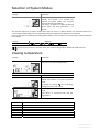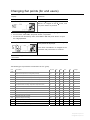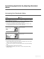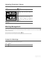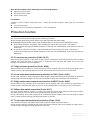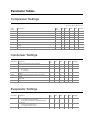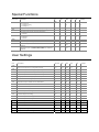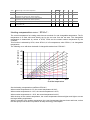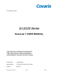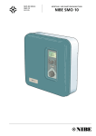
1
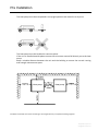
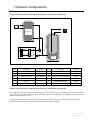
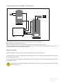
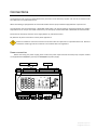
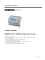
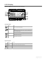
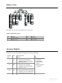
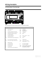
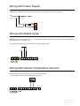
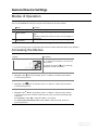
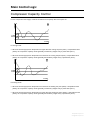
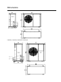
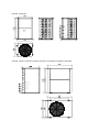
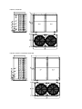
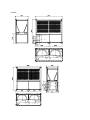
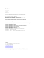
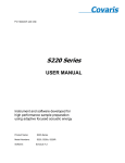
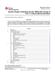
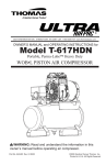
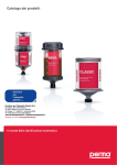
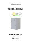
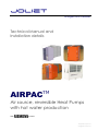
joliet
energies renouvelables
Technical Manual and
Installation details
AIRPAC
Air source, reversible Heat Pumps
with hot water production
With controller www.joliet‐europe.com info@joliet‐europe.com Pre Installation
The heat pump must be transported in an upright position and stored in at dry area. The heat pump must be installed on concrete plinth If the unit is installed outside please ensure that rain water cannot fall directly on to the heat pump. Keep a suitable distance between the unit and the building to ensure the normal running and enough maintenance space. Heat pump
Heat pump
Installation should be carried out according to local regulations by a competent heating engineer.
www.joliet‐europe.com info@joliet‐europe.com Hydraulic configurations
Using a heat pump for heating and domestic hot water production Buffer tank
HT
CT
ET
ST
FI
OT
ELK
VXV
RT
FI
VVB
P1
HEAT PUMP
Name
Description
Included
Name
Description
Included
P1
Circulation pump
Internal(Option)
RT
Return temperature sensor
Internal
ELK
Electric heater
Internal(Option)
ST
Flow temperature sensor
Internal
VXV
Change over Valve
External(Option)
OT
Outdoor temperature sensor
Internal
VVB
Hot water tank
-
HT
Hot water temperature
Internal
FI
Soft joint
-
CT
Condenser temperature
Internal
ET
Evaporating temperature
Internal
Using a heat pump for heating and domestic hot water production This configuration requires a three way valve (VXV) and an external water pump. The three way valve should be installed to give priority to domestic hot water provision. When the operator set temperature is achieved the three way valve will revert to supply the heating circuit. The hot water temperature sensor (HT) must be connected to the PC board and connected with the hot water tank. The internal electric immersion heater (ELK) start is determined by ST07 and ST08 www.joliet‐europe.com info@joliet‐europe.com Using a heat pump for heating and domestic hot water production, in relay with an existing boiler. Buffer tank
BOILER
VXV1
HT
CT
ET
ST
FI
OT
VXV
RT
FI
VVB
P1
HEAT PUMP
Name
Description
Included?
Name
Description
Included?
P1
Circulation pump
Internal(Option)
RT
Return temperature sensor
Internal
VXV
Change over Valve
External(Option)
ST
Flow temperature sensor
Internal
VVB
Hot water tank
-
OT
Outdoor temperature sensor
Internal
FI
Soft joint
-
HT
Hot water temperature
Internal
CT
Condenser temperature
Internal
ET
Evaporating temperature
Internal
This configuration requires a three way valve (VXV) and an external water pump. The three way valve should be installed to give priority to domestic hot water provision. When the operator set temperature is achieved the three way valve will revert to supply the heating circuit. The hot water temperature sensor (HT) must be connected to the PC board and connected with the hot water tank. When the boiler is started, change over valve VXV transfers to Boiler to make the heating water go through Boiler. Boiler’s start is set by ST07 and ST08. When you set ST07=SF02 and ST08=SF03, the unit will automatically transfer to Boiler heating or revert to Heat Pump heating. www.joliet‐europe.com info@joliet‐europe.com Using a heat pump for cooling + heat recovery Buffer tank
HT
P1
FI
P2
VVB
HEAT PUMP(CHILLER)
When cooling, A/C water pump P1 runs, hot water pump P2 runs for daily hot water. When heating, only A/C water pump P1 runs. When only hot water is required, only hot water pump P2 runs, the daily hot water is priority. The daily hot water sensor has already put into the electric box, one side is already connected with the controller, the other side should be put into the daily hot water tank. Pipe connections Pipework installation must be carried out in accordance with current norms and directives. The heat pump has a max return temperature of approximately 50℃ and an outgoing max temperature from the heat pump of approximately 60℃. It is recommended that the installation is fitted with shutoff valves (AV) these must be fitted outside of the heat pump to facilitate future service. The pipe work must be flushed before the heat pump is connected, so that any contaminants do not damage the components parts. www.joliet‐europe.com info@joliet‐europe.com Connections
The equipment must not be connected without the permission of the electricity supplier and must be connected under the supervision of a qualified electrician. When the building is equipped with an earth‐fault breaker the heat pump should be equipped with a separate one. The equipment must be protected by a dedicated fused switch. All internal electrical equipment except the outdoor temperature sensor are pre connected at the factory. The heat pump must be fitted with a dedicated earth fault breaker. Disconnect the heat pump from the mains supply before any maintenance work. Pay attention to phase connections in three phase applications. Electrical installation and service must be carried out under the supervision of a qualified electrician. Electrical installation and wiring must be carried out in accordance with local regulations. Power connection Before connecting the power supply, please confirm the power requirement of the heat pump. European models are supplied with 230V/1/50Hz (1 phase) and 400V/3/50Hz (3 phase) supply. Switch D4
G G0 PE
Terminals X4
Switch D5
D1 M D2 D3 M D4 D5 M
X1 GNDX2 X3 GNDX4 X5 GNDX6
+5V+24V
SIEMENS
+
PolyCoolRWR470. 10
RS485
Q13Q14Q24Q34Q44Q54Q64
Q23Q74Q84
Y1 G0 Y2
RJ45
GND
www.joliet‐europe.com info@joliet‐europe.com Temperature sensor for hot water The supplied sensor is connected using a two‐wire cable to terminal positions X4 on the main board.The sensor is placed in a submerged tube on the accumulator tank. A/C and heating main switch The air conditioner’s switch D4 must be ON when it is to be started. An external ON/OFF switch could be connected to start or stop the air conditioner port . Hot water switch The hot water switch D5 must be ON if you want to start the hot water function. An external ON/OFF switch could be connected to start or stop the hot water function. Indoor side water flow switch The water flow switch is to check if the water is flowing or not in the pipe system. If it is ON, the water is flowing and the compressor can be started; otherwise, the compressor is prohibited to start. The connection of the water flow switch, please refer to the unit electric diagram. Alarm output In case of an internal problem with the unit, there is alarm signal output. The user can connect an alarm unit (such as an indicator light, bell etc), for detailed information, please refer to the units electric diagram. www.joliet‐europe.com info@joliet‐europe.com Controller functions
POLYCOOL™ AC&R Controller
RWR470.10 for AIRPAC heat pump models
Key features are as follows: •
•
•
•
•
•
•
Non-programmable stand-alone controller, or networked via the communication of PCLBUS
Strict user privilege control
Multiple applications can be configured by setting parameters
Control of inlet/outlet water/water temperature
Fast application (with parameters) uploading and downloading via Poly Stick
Complete alarm and warning management
User-friendly icon HMI, LCD display and light blue backlight
www.joliet‐europe.com info@joliet‐europe.com LCD Display
Operation of RWR470.10 is fully driven by buttons and menus. Operating buttons
Button
Name
Use
<Esc>
In Menu /parameter setting mode, press it to return to the previous menu
level, or to reject the value entered
<Enter>
Press down it for more than 2 seconds and release it to enter the Menu
mode
In Menu/parameter setting mode, press it to confirm the selected menu
level, or the value entered
Press it to acknowledge/reset warnings and alarms
<Plus>
<Minus>
Press it for 2 seconds to activate the System Mode in stop mode
Or, press it to select the menu level, or to increase the value in
Menu/parameter setting mode
Press it to select the menu level, or to decrease the value in
Menu/parameter setting mode
Legend for menus
Icon
Meaning
Function
Query/view
Actual values of all temperature
Warning
Existence of warning, and the latest 10 warnings
Alarm
Existence of alarm and the latest 20 alarms
Parameters
Set parameters and values (see also Menu Tree)
www.joliet‐europe.com info@joliet‐europe.com The unit of compressor and pump running time is 100 hours. As for how to access the Query/Warning/Alarm/Parameter menus above, see also < Accessing the Menus> Parameters listed under the menu vary with the password privileged user. Before accessing the Parameter menu, select the user group (“NO” “EU” or “ID”) first and input the corresponding password that is required for the service men and factory users. See also <Chapter 10.2 Accessing the Parameter Menu> Legend for system Mode and status
On the right lower side, nine icons are used to indicate system modes and status. Icon
Meaning
Power on/Off
Cooling
Heating
Icon
Meaning
Hot water(The icon is displayed in
house)
compressor
Defrost
House (All devices within this icon are called indoor devices.)
When the device is activated, the corresponding icon will be lit.
Legend for devices
On the right middle area, the icons are used to indicate the work status of the devices. Icon
Meaning
Status and Indication
Compressor
On solid: Running
Blinking : Alarms related to compressor
Flow switch
Blinking: flow switch alarm
Indoor pump
On solid: running
Blinking: alarms detected
condenser fan
For any warning/alarm detected, the corresponding device icon and the the alarm is acknowledged or reset /
icon will blink continuously until www.joliet‐europe.com info@joliet‐europe.com Menu Tree
By default, end users can access all parameters in ST group. Legend for parameter groups
Code
CM
CN
EV
SF
Indication
Compressor settings
Condenser settings
Evaporator settings
Special functions
Code
ST
UI
AL
DF
Indication
Set points
User interface
Alarm settings
Defrost settings
Access Rights
Three groups of users with different privilege levels are described below. Privilege User Main Activities Level Special All Factory • Password required
• View information
ID User • Configure and commission
and status
EU Service •
Men •
NO End User •
•
applications by setting/adjusting
parameter values
Password required
Configure and commission
applications by setting/adjusting
parameter values
No password is required
Adjust limited values of parameters
(by default , can only adjust values
of parameters in the “ST” group)
• Acknowledge
warnings and
alarms
• Heating /Cooling
changeover
www.joliet‐europe.com info@joliet‐europe.com Wiring Examples Connection Terminals
Brief descriptions of the inputs and the outputs are summarized as follows. Terminal Assignments
Terminal Assignments
G
Power supply AC/DC 24 V
Q13
Supply 1 (AC 24 V …230 V)
G0
Power supply ground
Q14
Compressor1
PE
Safety ground
Q24
Compressor2
Q34
Indoor water pump
X1
Inlet water temperature of indoor side
Q44
Condenser fan
X2
Outlet water temperature of indoor side
Q54
4-way valve
X3
Atmospheric temperature of outdoor
Q64
Boiler
X4
Hot water temperature
X5
Condenser temperature
Q23
Supply 2 (AC 24 V …230 V)
X6
evaporating temperature Q74
3 way valve
GND
Common reference point for analogue input
Q84
Alarm
+5 V
DC 5 V power output for active sensor
Y1
Condenser fan 2
+24 V
DC 24 V power output for active sensor
GND
Common reference point
Y2
Analogue output 2, 0...10 V
D1
Water flow switch
D2
Low pressure switch
A+
A+ connector for RS485
D3
high pressure switch
B-
B- connector for RS485
D4
Air condition switch
GND
D5
Hot water switch
RJ45
Optional for RS485 communication
Service interface for parameters
uploading and downloading
M
Common reference point for digital input
www.joliet‐europe.com info@joliet‐europe.com Wiring with Power Supply
RWR470.10 is supplied with 24 VAC ± 20 % or 24 VDC ± 10 % via plug‐in terminals G and G0 Wiring with Digital Inputs
RWR470.10 offers five digital inputs for connecting safety devices, alarms, device status, and remote switches. These digital inputs are voltage free. The following figure represents an example of wiring the digital input Wiring with Passive Temperature Sensors
Before wiring with passive sensor, pay attention to the following: • Terminals X1…X6 can be wired with NTC 10K sensor.
www.joliet‐europe.com info@joliet‐europe.com General Device Settings Modes of Operation
The current RWR470.10 controller consists of three kinds of operation modes: Mode Function 1 2 3 Normal working mode Display all running devices and measured values View configured analogue inputs, warning and alarm Menu mode* logs Set/adjust parameter values and also user privilege to parameters Normally shut‐down status (all units stop running.) Stop mode** *To enter menu mode, see also <Chapter 4.2. Accessing the Menus>. • In normal working mode, the back light will be timed out after 30seconds without any operation.
Accessing the Menus
Display +
-
Procedures In Stop mode, press the <Enter> button for 2 seconds and release it to enter the Menu mode. By default, the Query icon is blinking, waiting for further instructions. .
To view the latest 10 warnings generated: • Navigate to the
menu by pressing <Plus> or <Minus>, and then press <Enter>
to confirm and proceed.
To view the latest 20 alarms generated: • Navigate to the
menu by pressing <Plus> or <Minus>, and then press <Enter>
to confirm and proceed.
To set parameter values: • Navigate to the
menu by pressing <Plus> or <Minus>, and then press <Enter>
to confirm and proceed. Contents under this menu may vary with the privilege right
of the user.
− For end users, select “NO,” and press <Enter > to proceed.
− For service men and factory users, select “EU” or ”ID” and press <Enter> to
input the password.
www.joliet‐europe.com info@joliet‐europe.com Selection of System Modes
Display Procedures In stop mode, press the <Plus> button for 2 seconds, and release it to activate the +
selection of system mode. The currently system mode will start flashing. Press <Plus> or <Minus> to select the desired system mode, and then press<Enter > to confirm. The selection sequence of system modes varies with the <Plus> or <Minus> button you selected based on the current system mode (SF01). The corresponding icon(s) for system mode will blink once selected. If the current system is heating and cooling (when SF01=1) , the full sequence of selecting the system modes will be as follows. Activity Sequence Press <Plus> B B .
appear at the same time, it is auto mode, the actual running mode is decided by ST18 and ST19. Viewing temperature
Display Procedures In normal working mode, press <plus> or <minus>to look into the temperature. Display +
.
Procedures In stop mode, press the <Enter> button for 2 seconds and release it to enter the Menu mode. By default, the Query icon is blinking, waiting for further instructions. Press the <Enter> button to enter the query mode. Press <plus> or <minus>to look into the temperature. Code RT ST OT HT CT ET Describe Inlet water temperature of indoor side
Outlet water temperature of indoor side
Atmospheric temperature of outdoor
Hot water temperature
Condenser temperature
Evaporating temperature www.joliet‐europe.com info@joliet‐europe.com Changing Set points (for end users)
Display Procedures In stop mode, press <Enter> for 2 seconds and release it to activate the Menu mode. When the icon is blinking, press <Plus> or <Minus> to navigate to the then press <Enter> to proceed. +
.
Contents under the menu, and Parameter Menu may vary with the privilege right of the user. • For end users, select “NO,” and press <Enter > to proceed.
• For service men and factory users, select “EU” or ”ID” and press <Enter> to input
the 4-digit password .
+
-
For end users, parameters in the “ST” group will by default be displayed. Press <Plus> and <Minus> to navigate to the parameter and press<Enter> to continue. Or, continuously press <Esc> to exit out of the current level and back to the desired menu level. .
The following list is parameters contained in the “ST” group. Para‐
meter Descriptions De‐fault Min. Max. Unit Res Privilege ST01
Set point of compressors in cooling mode (End User)
12
ST11
ST12
ºC/
0.1
0
ST02
Set point of compressors in heating mode (End User)
40
ST13
ST14
ºC/
0.1
0
ST03
Adjustable temperature band of compressor in Cooling mode
1
0
10
ºC
0.1
0
ST04
Adjustable temperature band of compressor in Heating mode
1
0
10
ºC
0.1
0
ST05
Setting temperature for heating temperature compensate function
20
0
30
ºC
0.1
0
ST06
Compensate factor for heating temperature compensate function
6
0
30
-
0.1
0
ST07
Temperature Scope of outside when the boiler started
0
-10
20
ºC
0.1
0
ST08
Set point of outside temperature when the boiler started
5
1
20
ºC
0.1
0
ST09
Set point of hot water temperature in the life
50
ST15
ST16
ºC
0.1
0
ST10
Band of hot water temperature in the life
3
1
10
ºC
0.1
0
ST11
Minimum set point in cooling
10
0
ST12
ºC
0.1
0
ST12
Maximum set point in cooling
40
ST11
60
ºC
0.1
0
ST17
Band of adjusting time
30
1
1000
Sec
1
0
ST18
Set point of running mode
25
15
30
ºC
0.1
0
ST19
Temperature Scope of running mode
5
1
10
ºC
0.1
0
www.joliet‐europe.com info@joliet‐europe.com Customizing Application by Adjusting Parameter Values Accessing the Parameter Menu
Display Procedures In Stop mode, press <Enter> for 2 seconds and release it to activate the Menu mode. When the icon is blinking, press <Plus> or <Minus> to navigate to the and then press <Enter> to proceed. Contents under the menu, menu may vary with the privilege right of the user. • For end users, select “NO” and press <Enter > to proceed.
• For service men and factory users, select “EU” or “ID” and press <Enter>. Input
the 4-digit password when the following screen is displayed
Press <Enter> to confirm and continue to input the password. +
.
Password is required for the sevice man and factory users. +
.
Input Password
To input password, follow the instructions below: • When the digit is blinking, press <Plus>/<Minus> to select the value. Then, press
<Enter> to confirm, and proceed to the next digit.
• Or, press <Esc> at any time to cancel the input and return to the previous blinking
digit.
• Repeat steps above to input other three numbers.
• After inputting the password, press <Enter> to confirm, and proceed to setting
parameter values.
www.joliet‐europe.com info@joliet‐europe.com Adjusting Parameter Values
Procedures
Display Procedures After inputting password and enter into the parameter setting mode, the “ST” parameter group will by default be displayed. Press <Plus> or <Minus> to select the parameter code, and press <Enter> to confirm. The default value of the parameter will start flashing, allowing you to make a change. Press <Plus> or <Minus> to increase or decrease the value, and press <Enter> to confirm. Continuously press <Esc> to exit out of the current level and back to the desired menu level. Warning Management When a warning is detected, the corresponding warning code will be displayed on the LCD. The warning icon will flash simultaneously. Only the latest 10 warnings will be kept under the menu. Upon power failure of the controller, the warning logs will be erased and recounted Codes for Warnings
Ten types of warnings are used to monitor the system. Codes
WN00
Meaning
WN01
www.joliet‐europe.com info@joliet‐europe.com Viewing Warning Logs
Display Procedures Press down <Enter> for 2 seconds and release it to activate the Menu mode. When the icon is flashing, press <Plus>/ <Minus> to navigate to the menu, and then press <Enter> to confirm. Two letters “WN” will be displayed on the LCD, continuously flashing. Press <Enter> again to view the last 10 warning codes generated, if any. If no warning is generated, the word “None” will be displayed. Continuously press <Exit> to exit out of the current level, and back to the normal running mode. Alarm Management Alarms in PolyCool470.10 are divided into two groups: auto reset alarms and manual reset alarms. • For an auto reset alarm, users are not required to acknowledge and reset it. The corresponding device will be
automatically restarted once the alarm status disappears.
• Once a manual reset alarm is detected, the system will be stopped. Users need acknowledge and reset it, and
also manually restart the corresponding device after the fault status is cleared.
When an alarm is detected, the corresponding device icon (if any) and the alarm code will be displayed on the screen. icon will continuously flash. An • If more than one alarm is detected, the alarm codes will be displayed successively on the LCD screen until the
alarm status disappears, or until they are manually acknowledged or reset (only for manual reset alarms).
• If the system detects warnings and alarms at the same time, the warning codes will NOT be displayed on the
LCD.
• The latest 20 normal alarms and manual reset alarms generated in total are separately kept under the auto
menu.
reset alarm (AR) and manual reset alarm (MR) categories in the
Auto Reset Alarms
The following are codes for auto reset alarms with their meanings. Codes
AL01
Meaning
Compressor low pressure (DI2)
AL02
Compressor high pressure (DI3)
AL03
Low inside supply water temperature protection (when less than AL01 in cooling mode)
AL05
Inside supply temperature is over the high limit in heating mode(when over than AL03 in
heating mode)
www.joliet‐europe.com info@joliet‐europe.com Manual Reset Alarms
The following are codes for manual reset alarms with their meanings. Codes
AL17
AL18
AL19
AL20
Meaning
Flow switch alarm after the delay (AL05)
Alarm number of compressor low pressure within 24 hours is over the limit (AL06)
Alarm number of compressor high pressure within 24 hours is over the limit (AL07)
Low evaporator temperature protection (AL08)
Viewing Alarm Logs
Display Procedures Press down <Enter> for 2 seconds, and release it to activate the Menu mode. Press <Plus> or <Minus> to navigate to the menu, and then press <Enter> to confirm. By default, auto reset alarm “AR” will be displayed on the LCD, flashing. To view auto reset alarms generated, press <Enter> to continue when “AR” is displayed. To view manual reset alarms, press<Minus> or <Plus> to navigate to the “MR” group, and then press <Enter> to continue. By default, the first manual reset alarm “MR01” will be displayed as follows. Press <Enter> to view the first manual reset alarm code. Or, press<Minus> or <Plus> to view other numbered alarms, and press<Enter> to view the specific code. If no alarm is generated, the word “NoNE” will be displayed. Continuously press <Exit> to exit out of the current level, and back to the normal running mode. MR01 and AR01 are respectively the latest information of manual reset alarm and auto reset alarm. www.joliet‐europe.com info@joliet‐europe.com Acknowledging and Resetting Manual Reset Alarms
Any alarm detected by the system, either an auto reset alarm or a manual reset alarm, will be displayed on the LCD. However, only manual reset alarms require user’s acknowledgement and reset. To do this, follow the steps below: • Press <Enter> to acknowledge the alarm.
• If the alarm status is cleared, the corresponding device icon and alarm icon
disappear.
• Restart the system, as appropriate.
that are flashing will accordingly
www.joliet‐europe.com info@joliet‐europe.com Main Control Logic Compressor Capacity Control
For the compressor with stages, it will be started with full capacity when the system on. In cooling mode: • When the actual supply/return temperature is higher than the cooling set point (ST01) + temperature band
(ST03), the compressor capacity will be gradually increased by stages every a preset time (ST17).
• When the actual supply/return temperature is lower than the cooling set point (ST01) - temperature band
(ST03), the compressor capacity will be gradually decreased by stages every a preset time (ST17).
In heating mode: • When the actual supply/return temperature is lower than the heating set point (ST02) - temperature band
(ST04), the compressor capacity will be gradually increased by stages every a preset time (ST17).
• When the actual supply/return temperature is higher than the heating set point (ST02) + temperature band
(ST04), the compressor capacity will be gradually decreased by stages every a preset time (ST17).
www.joliet‐europe.com info@joliet‐europe.com Temperature compensation at HEAT
z
z
z
z
The controller offers two type of temperature control mode at heat mode.
When SF04=0, the set‐temperature at heat will be controlled by ST02; When SF04=1, the set‐temperature at heat will be controlled by ambient‐temperature (OT) ,ST05 and ST06 according to the following formula: Set‐temperature at HEAT =ST05+ST06 (ST05‐OT) The calculated temperature can be used for the control reference, but the maximum date will not exceed ST14 Boiler
When heating mode is operating, BOILER will run as follows: When OT < ST07 BOILER will run as a energy stage by temperature requirement, but BOILER is the last to be activated, the first to quite from working. When OT > ST07+ST08, BOILER function is cancelled. When OT < SF02, heat pump (compressor) is not running and will not react if asked for hot water. If asked for heating, it woks as follows: Start indoor side water pump, BOILER works, BOILER’s running follows the temperature requirement. When OT > SF02+SF03, heat pump reverts to normal working. 3 way valve control
z
z
When SF10=0, DO7 will control the 3 way valve. Both the indoor side water pump and 3 way valve will be turned on when running the daily hot water mode. When SF10=1, DO7 will control the daily hot water pump. The indoor side water pump is OFF, the daily hot water pump will be ON when running daily hot water mode. Alarm
The alert Produced namely output, the alert clearance namely stop exportation. Defrost at heating or hot water mode
Access defrost condition (to be meet at the same time)
z Outdoor temperature (OT) <DF03 z The interval time of defrost between the first and second time > DF06 z Temperature difference (OT‐CT) > DF04 time, last DF05 www.joliet‐europe.com info@joliet‐europe.com Quit defrost condition (quit when any of the following appear)
z High pressure protection z Coil temperature ≥ DF09 z Defrost time ≥ DF10 Fan defrost
If DF01=1, and the outdoor temperature (OT) > DF02, after defrost conditions appear, get into fan defrost process z Turn OFF compressor z Outdoor fan runs until the coil temperature > 3℃, finish defrost. Protection function
9.7.1 Anti‐freeze protection at stop situation The anti‐freeze function will be valid only at the following conditions: z The controller keeps at stop mode, but the unit is still connected with power supply.
z OT≤SF06 (During anti-freeze working, when OT≥SF06+SF07, it will quite from the anti-freeze running.)
z
z
At the above conditions, and SF02=1, when ST≤SF08, the indoor side water pump is turned ON, a continuous blink warning code WN01 will appear on the LCD, until ST≥SF08+SF09, it will quite from the anti‐
freeze work. At the above conditions, and SF03=1. when STO≤SF08, the outdoor side water pump is turned ON, a continuous blink warning code WN02 will appear on the LCD, until ST≥SF08+SF09, it will quite from the anti‐
freeze work. 9.7.2 Low pressure protection (Code: AL01)
After starting the compressor, it will check the low pressure at AL09 delay. If DI2=OFF, all the compressors will be stopped, other parts will keep its original state. A continuous blink code AL01 will appear on the LCD, until DI2=ON, the unit will turn to its normal work. 9.7.3 High pressure protection (Code: AL02)
Whenever DI3=OFF is checked out, all the compressors will be stopped, other parts will keep its original state. A continuous blink code AL02 will appear on the LCD, until DI2=ON, the unit will turn to its normal work. 9.7.4 Low outlet water temperature protection at COOL (Code: AL03)
At cool mode, if ST≤AL01, all the compressors will be stopped, other parts will keep its original state. A continuous
blink warning code AL03 will appear on the LCD, until ST≥AL01+AL02, the unit will turn to its normal work.
9.7.5 High outlet water temperature protection at HEAT (Code: AL05)
At heat mode running, ST≥AL03, all the compressors will be stopped, other parts will keep its original state. A continuous blink code AL05 will appear on the LCD, until ST≤AL03+AL04, the unit will turn to its normal work. 9.7.6 Water flow switch protection (Code: AL17)
At normal working condition, if there is no signal from water flow switch within AL05 after starting the outdoor side water pump, a continuous blink warning code AL017 will appear on the LCD. During unit working, when check FS=OFF, all the compressors will be stopped, other parts will keep its original state, a continuous blink warning code AL017 will appear on the LCD. 9.7.7 Low evaporate temperature protection (Code: AL20)
The protection function will be valid at COOL mode as well as at HEAT mode when SF03=1 During normal working, if ET≤AL08, all the compressors will be stopped, other parts will keep its original state, a continuous blink warning code AL20 will appear on the LCD. www.joliet‐europe.com info@joliet‐europe.com Parameter Tables Compressor Settings
<Second: Sec; Minute: Min; Hour: Hr> Parameter
CM01
Compressor minimum ON time
CM02
Compressor minimum OFF time
180
1
1000
Sec
1
1
CM03
Start Delay between two compressors
10
0
100
Sec
1
1
CM04
Shut down delay between two compressors
30
0
1000
Sec
1
1
CM05
Compressor ON delay (outdoor pump ON)
10
0
150
Sec
1
1
CM06
The number of compressors
2
1
2
-
1
2
CM07
The direction indicator of four-way valves( 1 or 0 indicates heating
mode)
Compressor consecutive running time for discard
1
0
1
30000
0
50000
CM08
Descriptions
Default
180
Min.
Max.
Unit
Res.
Privilege
1
1000
Sec
1
1
1
Hr
10
Condenser Settings
Para-meter
Descriptions
Min
Max
Unit
Res.
Privilege
Outdoor pump ON delay (indoor pump ON)
Default
10
CN01
0
150
Sec
1
1
CN02
Outdoor pump ON delay (compressor OFF)
10
0
150
Sec
1
1
CN03
Control mode
0
0
1
-
1
1
25
15
50
℃
0.1
1
20
0
30
℃
0.1
1
25
15
30
℃
0.1
1
45
40
50
℃
0.1
1
Default
Min.
Max.
Unit
Res.
Privilege
0
0
1
-
1
1
0
0
1
-
1
1
60
CN02
1000
Sec
1
1
-
CN04
CN05
CN06
CN07
0= fix fan speed
1= two fan speed
Adjustable outdoor temperature band of fan speed at
cooling
Adjustable outdoor temperature band of fan speed at
heating
Adjustable outdoor temperature band of fan speed at hot
water mode
Adjustable hot water temperature band at hot water mode
Evaporator Settings
Para-meter
Descriptions
EV01
Control Mode
0=pump with circulate continuously
1= The water pump with the compressor ON/ OFF
but ON/ OFF
EV02
Indoor reference sensor:
-
EV03
- 0=RT (return temperature sensor)
1=ST (supply temperature sensor)
Indoor pump Off delay (compressor OFF)
1
Special Functions
Para‐meter Descriptions SF01
System mode
De‐
fault Min. Max. Unit Res. Privilege - 0=Cooling only
- 1=Heating & Cooling
- 2=Heating only
2
0
2
-
1
2
Temperature point to prohibit heat pump working
-10
-20
20
℃
Temperature scope to prohibit heat pump working
The compensates function of heating temperature 2
1
10
℃
0.1
0.1
1
1
1
0
1
-
1
1
- 0=Disabled
- 1=Enabled
0
0
1
-
1
2
SF06
Outside temperature point for antifreeze turned on
2
0
10
1
1
SF07
Outside temperature scope for antifreeze turned off
1
1
10
1
1
SF08
Temperature point of inlet/outlet
turned on
water for antifreeze
3
1
10
1
1
SF09
Temperature point of inlet/outlet
turned off
water for antifreeze
3
1
10
1
1
SF02
SF03 SF04
SF05
- 0=Disabled
- 1=Enabled
Heat Recovery function
User Settings
Para‐
meter Descriptions De‐fault Min. Max. Unit Res Privilege ST01
Set point of compressors in cooling mode (End User)
12
ST11
ST12
ºC/
0.1
0
ST02
Set point of compressors in heating mode (End User)
40
ST13
ST14
ºC/
0.1
0
ST03
Adjustable temperature band of compressor in Cooling mode
1
0
10
ºC
0.1
0
ST04
Adjustable temperature band of compressor in Heating mode
1
0
10
ºC
0.1
0
ST05
Setting temperature for heating temperature compensate function
20
0
30
ºC
0.1
0
ST06
compensate factor for heating temperature compensate function
6
0
30
-
0.1
0
ST07
Temperature Scope of outside when the boiler started
0
-10
20
ºC
0.1
0
ST08
Set point of outside temperature when the boiler started
5
1
20
ºC
0.1
0
ST09
Set point of hot water temperature in the life
50
ST15
ST16
ºC
0.1
0
ST10
band of hot water temperature in the life
3
1
10
ºC
0.1
0
ST11
minimum set point in cooling
10
0
ST12
ºC
0.1
0
ST12
maximum set point in cooling
40
ST11
60
ºC
0.1
0
ST13
minimum set point in heating
20
0
ST14
ºC
0.1
1
ST14
maximum set point in heating
55
ST13
80
ºC
0.1
1
ST15
minimum set point of hot water temperature in the life
20
0
ST16
ºC
0.1
1
ST16
maximum set point hot water temperature in the life
55
ST15
80
ºC
0.1
1
ST17
band of adjusting time
30
1
1000
Sec
1
0
ST18
Set point of running mode
25
15
30
ºC
0.1
0
ST19
Temperature Scope of running mode
5
1
10
ºC
0.1
0
Defrost Settings
Para‐
meter Descriptions Default
Min. Max. Unit Res Privilege DF01
Fan defrost
1
0
1
-
1
1
Set point of outdoor temperature when fan defrost
(When outdoor temperature ≥the set point and DF01=1, adopt fan
defrost)
5.0
1.0
10.0
ºC
0.1
1
DF03
Set point of outdoor temperature
10.0
3.0
20.0
ºC
0.1
1
DF04
Set point of defrost temperature difference (outdoor temperature-coil
temperature)
Running time
(compressor continuous running time when coil temperature
≤DF04)
10
5
20
ºC
0.1
1
5
1
60
Min
1
1
30
15
60
Min
1
1
10
6
180
Sec
1
1
10
6
180
Sec
1
1
- 0=Disabled
- 1=Enabled (when outdoor temperature ≥DF02)
DF02
DF05
DF06
Minimum defrost interval
DF07
Compressor transfers delay from OFF to ON before defrost, from
heating to cooling
Compressor transfers delay from OFF to ON after defrost, from
heating to cooling
DF08
DF09
Coil temperature when quite from defrost
5
1
20
ºC
0.1
1
DF10
Defrost time ( from compressor ON)
300
1
1000
Sec
1
1
DF11
Minimum air conditioner’s keep temperature
15
10
40
ºC
0.1
1
User Interface
Para‐
meter Descriptions De‐fault Min. Max. Unit Res. Privilege UI01
Password for service user
1234
0
9999
-
1
1
UI02
Password for factory user
4321
0
9999
-
1
2
Alarm Settings
Para‐
meter Descriptions De‐
fault Min. Max. Unit Res. Privilege AL01
Protecting Set point for low outlet water temperature
3
1
10
ºC
1
1
AL02
Band of low outlet water temperature
2
1
10
ºC
1
1
AL03
Protecting Set point for high outlet water temperature
55
1
100
ºC
1
1
AL04
Band of high outlet water temperature
15
1
20
ºC
1
1
AL05
Feedback Delay for water current switch
10
1
100
Sec
1
1
AL06
total alarm number within 24 hours in low pressure
(Over this limit, alarm “AL18” will be reported.)
total alarm number within 24 hours in high pressure
(Over this limit, alarm “AL19” will be reported.)
4
1
10
-
1
1
6
1
10
-
1
1
AL07
AL08
Protecting Set point for low evaporator temperature
-2
-10
10
ºC
0.1
1
AL09
Time rang during which low pressure will be ignored when
compressor ON.
300
0
1000
Sec.
10
1
Heating compensation curve(SF04=1)
RT/ST temperature
The control temperature for heating mode has two methods: fix and changeable temperature. The fix
temperature is a fixed value and directly set by the end user from the set area. The changeable
temperature is determined by values of ST05, ST06 and the tested outdoor temperature by the
controller.
This function is selected by SF04, when SF04=0, it is fix temperature; when SF04=1, it is changeable
temperature.
The following curve will show the detail of changeable mode when ST05=20℃
℃
100
20
17
15
90
13
80
11
70
9
60
7
50
5
40
3
30
20
10
0
-10
-20
-30℃
Outside temperature
Set the heating compensation coefficient ST06 is 5,
When outdoor temperature is 5℃, the control temperature is 28℃;
When outdoor temperature is -10℃, the control temperature is 35℃;
When outdoor temperature is –20℃, the control temperature is 40℃;
With the drop of the outdoor temperature, the control temperature become higher and higher to meet
the large heating requirement.
With the increase of the outdoor temperature, the control temperature become lower and lower, so that
the heat pump works under low pressure to keep low energy consumption. Dimensions
LSQ06R1/C water outlet
water inlet
LSQ08R1/C, LSQ10R1/C, LSQ08R1/CR, LSQ10R1/CR Heater water
outlet
Heater water
inlet
A/C water
outlet
A/C water
inlet
LSQ10R1, LSQ10R1/R Heater water
outlet
Heater water
inlet
A/C water
outlet
A/C water
inlet
LSQ13R1, LSQ15R1, LSQ13R2, LSQ15R2, LSQ13R1 /R, LSQ15R1/R, LSQ13R2/R, LSQ15R2/R Heater water
outlet
Heater water
inlet
A/C water
outlet
A/C water
inlet
LSQ20R2, LSQ20R2/R Heater water
outlet
Heater water
inlet
A/C water
outlet
A/C water
inlet
LSQ25R2, LSQ31R2, LSQ25R2/R, LSQ31R2/R Heater water
outlet
Heater water
inlet
A/C water
outlet
A/C water
inlet
LSQ66R2 Water outlet
Water inlet
Heater water
outlet
A/C water
outlet
Heater water
inlet
A/C water
inlet
Standards EC Directives: 73/23/EEC 89/336/EEC Household and similar electrical appliances. Electromagnetic fields EMC Low voltage directive 2006/95EC BS EN 60335‐1‐:2002+A1 : 2004+A11 : 2004+A12 : 2006+A2 : 2006 BS EN 60335‐2‐40:A1 : 2006+A11 : 2004+A12 : 2005 Specification for safety of household and similar electrical appliances. EMC Directive 2004/108/EC EN55014‐1 : 2000+A1 :2001+A2 : 2002 Power disturbances test & Terminal voltage test EN55014‐2 : 1997+A1 : 2002 EN55014‐2 (EN61000‐4‐2), ESD test EN55014‐2 (EN61000‐4‐3), Radio frequency electromagnetic fields test EN55014‐2 (EN61000‐4‐4), Fast transients test EN55014‐2 (EN61000‐4‐5), Surges test EN55014‐2 (EN61000‐4‐6), Injected currents test EN55014‐2 (EN61000‐4‐11), Voltage dips and interruptions test EN61000‐3‐2 : 2006 Harmonics test EN61000‐3‐3 : 1995+A1 : 2001+A2 : 2005 Voltage fluctuation test Contact Tel. 00 34 972 505 557 ou 00 34 972 67 77 98 Fax. 00 34 972 67 77 96 Info@joliet‐europe.com www.joliet‐europe.com JOLIET (ENERGY) TECHNOLOGY SL Placa Europa 45 17600 Figueres Girona Joliet Technology SL – Reg. B63850549 – CL Balmes 152 – 08008 Barcelona