1
If necessary connecting cables of the sensors can be prolonged.
Recommended length that does not affect the measurement is to 100m.
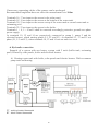
Terminals 16, 17 are input to the sensor in the solar panel.
Terminals 18, 19 are input to the sensor at the bottom of the water tank.
Terminals 20, 21 are input to the sensor on top of the water tank or secand water tank or
swimming pool.
Terminals 22, 23 are input to the sensor in the boiler.
Terminals 1 ÷ 4, 5 ÷ 8 and 9 shall be conected accordingly protective ground zero phase
power supply.
At terminals 10, 12 and 14 are respectively connected to pump 1, pump 2 and the
electrical heaters, which starting phase (L1, L2 and L3). At terminals 11, 13 and 15 out
phase (L1, L2 and L3), when terminals 10, 12 and 14 not out and vice versa.
6. Hydraulic connection
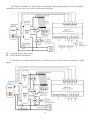
Example of a system with one heater, system with 2 tank (buffer tank, swimming
pool). Heated by solar panels, boiler and electrical heaters.
A) Heatingt water tank with boiler, solar panels and electric heaters. With a common
pump tank and heating.
PT - working heater thermostat
BT - block heater thermostat
8