1
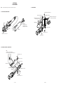
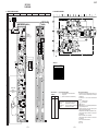
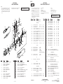
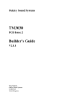
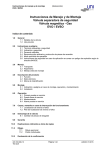
C-357
SERVICE MANUAL
SECTION 1
GENERAL
This section is extracted from
instruction manual.
US Model
Canadian Model
AEP Model
Ver 1.0 1999. 02
SPECIFICATIONS
CONDENSER MICROPHONE
MICROFILM
Notes on chip component replacement
• Never reuse a disconnected chip component.
• Notice that the minus side of a tantalum capacitor may be
damaged by heat.
—2—
SECTION 2
DISASSEMBLY
Note :
2-3. AMP BOARD
Follow the disassembly procedure in the numerical order given.
2-1. CASE ASSY, MICROPHONE
7 Two screws (+PTPWH 2 × 5)
3 Remove soldering
1 Remove soldering
5 Remove three solderings and
remove the three harnesses.
6 Remove the two solderings
and remove the harness.
A
8 AMP board
4 Screw
1 Ring, screw
Turn the Ring, screw
in the direction of the
arrow A, and remove it.
3 Screw
9 Transformer, output
2 Grip
2 Terminal, minus
5 Case assy, microphone
4 Terminal, plus
2-2. CHASSIS, “SLEEVE, CONNECTOR”
Note:
To re-attach it, turn the PAD knob
first in the direction of the arrow and attach it.
3 Screw (+P 2 × 6)
4 Terminal, ground
1 Two screws
2 Two screws
5 Chassis
8 Sleeve, connector
6 Screw
(+K 2 × 5)
7 Two screws (+K 2 × 5)
—3—
—4—
C-357
SECTION 3
DIAGRAMS
3-1. PRINTED WIRING BOARD
1
A
3-2. SCHAMITIC DIAGRAM
2
SW1
(DIRECTIVITY)
OMNI UNI
3
4
5
6
7
8
AMP BOARD
BLU
0
(SIDE B)
(DIRECTIVITY)
C16
YEL
OMNI
H
MIC1
CAPSULE
C2
R24
BRN
UNI
C3
R25
B
AMP BOARD (SIDE A)
BRN
MIC1
CAPSULE
C16
0.0012
D5
D4
R3
999.99M
S
R9
C
–2
•TOTAL CURRENT
7 mA
D-D CONV.
V
DRY BATTERY
SIZE"AA"
(IEC DESIGNATION R6)
1PCS,1.5V
OFF
C13
C6
CL-220HR-C
0dB
-10dB
CHECK
( BATTERY
)
INDICATOR
R16
C5
C15
RED
YEL
R22
C4
BLU
SW3
PAD
• Waveform
GRN
SW3
R23
POWER/LOW-CUT
M
R10
R8
R18
0dB
46.4
Q2 E C
R7
D
R25
47K
POWER
/LOW-CUT
–1
B
H
19.6
24.0
SW2
R4
R1
R2
R5
R19
R24
100K
999.99M
BATTERY
CHECK
INDICATOR
TYPE
POWER/LOW-CUT
C1
Q1
D5
E
0
0
YEL
R6
BLK
1 D6
WHT
-10dB
ANODE
5µsec/div
20V/div
R11
T1
D1
F
C7
R17
IC1
3
C14
1
2
G
D7
• Semiconductor
5 D6
2
3
H
6
1
Location
4
T2
D3
DRY BATTERY
SIZE"AA"
(IEC DESIGNATION R6)
1PCS,1.5V
R21
R20
RED
Ref. No.
L1
C9
R14
C10
CN1
R13
2
3
I
WHT
L2
C12
1
D2
R15
C11
R12
Location
D1
D2
D3
D4
D5
D6
D7
F-3
I-3
H-3
B-3
B-3
G-3
G-2
IC1
G-2
Q1
Q2
Q3
B-5
C-3
I-3
Note on Printed Wiring Board:
• X : parts extracted from the component side.
®
•
: Through hole.
• b : Pattern from the side which enables seeing.
Caution:
Pattern face side:
(Side B)
Parts face side:
(Side A)
Parts on the pattern face side seen from
the pattern face are indicated.
Parts on the parts face side seen from
the parts face are indicated.
Q3
C
PUL
C8
B
E
J
1-671-801-
12
1-671-801-
12
16
—5—
—6—
Note on Schematic Diagram:
• All capacitors are in µF unless otherwise noted. pF: µµF
50 WV or less are not indicated except for electrolytics
and tantalums.
• All resistors are in Ω and 1/4 W or less unless otherwise
specified.
•
%
: indicates tolerance.
• C : panel designation.
• U : B+ Line.
• Power voltage is dc 1.5 V and fed with regulated dc power
supply from battery terminal.
• Voltages and waveforms are dc with respect to ground
under no-signal (detuned) conditions.
• Voltages are taken with a VOM (Input impedance 10 MΩ).
Voltage variations may be noted due to normal production tolerances.
• Waveforms are taken with a oscilloscope.
Voltage variations may be noted due to normal production tolerances.
• Circled numbers refer to waveforms.
• Signal path.
F : MIC
C-357
SECTION 4
EXPLODED VIEWS
NOTE:
• -XX, -X mean standardized parts, so they may
have some differences from the original one.
• Items marked “*” are not stocked since they
are seldom required for routine service. Some
delay should be anticipated when ordering these
items.
•
SECTION 5
ELECTRICAL PARTS LIST
AMP
The mechanical parts with no reference number
in the exploded views are not supplied.
When indicating parts by reference number,
please include the board name.
#4
18
17
NOTE:
• Due to standardization, replacements in the
parts list may be different from the parts
specified in the diagrams or the components
used on the set.
• -XX, -X mean standardized parts, so they
may have some difference from the original
one.
• Items marked “*” are not stocked since they
are seldom required for routine service.
Some delay should be anticipated when
ordering these items.
Ref. No.
Part No.
Description
16
15
23
13
20
#3
12
14
21
•A
#2
#1
11
CN1
(including •A)
#1
5
4
3
7
8
Remarks
C1
C2
C3
C4
C5
1-130-467-00
1-130-776-00
1-107-202-00
1-113-642-11
1-113-981-11
MYLAR
MYLAR
MICA
TANTAL. CHIP
TANTAL. CHIP
470PF
0.47uF
10PF
47uF
22uF
5%
10%
5%
20%
20%
50V
63V
500V
10V
20V
C6
C7
C8
C9
C10
1-135-073-00
1-126-204-11
1-126-400-11
1-104-760-11
1-104-760-11
TANTALUM CHIP
ELECT CHIP
ELECT CHIP
CERAMIC CHIP
CERAMIC CHIP
0.33uF
47uF
22uF
0.047uF
0.047uF
10%
20%
20%
10%
10%
35V
16V
35V
50V
50V
C11
C12
C13
C14
C15
1-104-760-11
1-104-760-11
1-113-642-11
1-113-981-11
1-130-776-00
CERAMIC CHIP
CERAMIC CHIP
TANTAL. CHIP
TANTAL. CHIP
MYLAR
0.047uF
0.047uF
47uF
22uF
0.47uF
10%
10%
20%
20%
10%
50V
50V
10V
20V
63V
C16
1-104-540-11 FILM CHIP
10
#1
D1
D2
D3
D4
D5
2
6
D6
D7
2
9
1
0.0012uF 5%
8-719-016-74
8-719-977-22
8-719-016-74
8-719-016-74
8-719-052-72
DIODE
DIODE
DIODE
DIODE
LED
1SS352
DTZ9.1
1SS352
1SS352
CL-220HR-C
(BATTERY CHECK INDICATOR)
8-719-820-41 DIODE
8-719-975-40 DIODE
•
COILS
uH: µH
SEMICONDUCTORS
In each case, u: µ, for example:
uA...: µA... , uPA... , µPA... ,
uPB... , µPB... , uPC... , µPC... ,
uPD..., µPD...
Ref. No.
Part No.
Description
Remarks
R4
R5
R6
R7
R8
1-216-089-91
1-216-081-00
1-216-045-00
1-216-077-00
1-216-033-00
RES,CHIP
METAL CHIP
METAL CHIP
METAL CHIP
METAL CHIP
47K
22K
680
15K
220
5%
5%
5%
5%
5%
1/10W
1/10W
1/10W
1/10W
1/10W
R9
R10
R11
R12
R13
1-216-121-91
1-216-085-00
1-216-049-91
1-216-097-91
1-216-081-00
RES,CHIP
METAL CHIP
RES,CHIP
RES,CHIP
METAL CHIP
1M
33K
1K
100K
22K
5%
5%
5%
5%
5%
1/10W
1/10W
1/10W
1/10W
1/10W
R14
R15
R16
R17
R18
1-216-057-00
1-216-057-00
1-208-291-11
1-216-033-00
1-216-055-00
METAL CHIP
METAL CHIP
RES,CHIP
METAL CHIP
METAL CHIP
2.2K
2.2K
4.7M
220
1.8K
5%
5%
5%
5%
5%
1/10W
1/10W
1/10W
1/10W
1/10W
R19
R20
R21
R22
R23
1-216-073-00
1-208-291-11
1-208-291-11
1-218-179-11
1-208-291-11
METAL CHIP
RES,CHIP
RES,CHIP
RES,CHIP
RES,CHIP
10K
4.7M
4.7M
10M
4.7M
5%
5%
5%
5%
5%
1/10W
1/10W
1/10W
1/10W
1/10W
R24
R25
1-216-097-91 RES,CHIP
1-216-089-91 RES,CHIP
100K
47K
5%
5%
1/10W
1/10W
50V
< DIODE >
SW1
•
When indicating parts by reference number,
please include the board name.
< CAPACITOR >
15
22
•
CAPACITORS:
uF: µF
RESISTORS
All resistors are in ohms.
METAL: metal-film resistor
METAL OXIDE: Metal Oxide-film resistor
F: nonflammable
A-4542-563-A AMP BOARD, COMPLETE
********************
*
19
•
1SS302
RB411D
< SWITCH >
SW2
SW3
1-570-056-11 SWITCH, SLIDE (POWER/LOW-CUT)
1-762-742-31 SWITCH, DETECTION (SMALL TYPE) (PAD)
< TRANSFORMER >
T1
1-431-068-11 TRANSFORMER, OUTPUT
T2
1-429-721-21 TRANSFORMER, DC-DC CONVERTER
************************************************************
< IC >
IC1
Ref. No.
Part No.
Description
1
2
* 3
4
* 5
X-2542-164-1
3-736-363-11
2-545-579-01
A-4540-552-A
2-545-573-01
CASE ASSY, MICROPHONE
TAPPING
STOPPER, CAPSULE
CAPSULE ASSY
FRAME
* 6
7
8
9
10
2-545-580-01
2-544-797-01
2-544-798-01
2-545-576-01
2-545-578-01
PANEL, BLIND
TERMINAL, PLUS
TERMINAL, MINUS
GRIP
JOINT
* 11
* 12
13
* 14
15
2-545-574-01
2-545-577-01
2-545-598-01
A-4542-563-A
3-736-363-21
SLEEVE, CONNECTOR
RING, SCREW
LABEL, MODEL NUMBER
AMP BOARD, COMPLETE
TAPPING
Remarks
Ref. No.
Part No.
Description
* 16
* 17
18
19
* 20
2-545-572-01
2-545-613-01
2-545-581-01
2-545-575-01
2-545-582-01
CHASSIS
TERMINAL, GROUND
KNOB (UPPER), PAD
KNOB, POWER (POWER/LOW-CUT)
SPRING, PAD
21
22
23
CN1
SW1
2-545-597-01
2-545-594-01
1-696-448-11
1-563-175-61
1-552-190-00
KNOB (LOWER), PAD
COVER, LED
CORD, MICROPHONE (DIA.5) (4 CORE)
CANNON XLR3-14 PIN INSERT
SWITCH, SLIDE (PAD)
#1
#2
#3
#4
7-627-452-38
7-685-103-19
7-627-551-18
7-627-553-68
SCREW,PRECISION +K 2 × 5
+ PTPWH (2 × 5)
SCREW,PRECISION +P 1.4 × 2
SCREW,PRECISION +P 2 × 6
MISCELLANEOUS
**************
CN1
1-563-175-61 CANNON XLR3-14 PIN INSERT
SW1
1-552-190-00 SWITCH, SLIDE (DIRECTIVITY)
************************************************************
8-759-564-83 IC XC6371A701PR
Remarks
< COIL >
L1
L2
1-412-963-11 INDUCTOR
1-412-963-11 INDUCTOR
100uH
100uH
< TRANSISTOR >
Q1
Q2
Q3
8-729-203-02 TRANSISTOR
8-729-230-63 TRANSISTOR
8-729-230-63 TRANSISTOR
2SK30A-O
2SC4116-YG
2SC4116-YG
1-696-448-11
2-100-951-04
2-100-952-00
2-545-055-01
2-545-148-01
999.99M
999.99M
10K
3-865-087-11 MANUAL, INSTRUCTION
(GERMAN, DUTCH, ITALIAN) (AEP)
3-865-087-21 MANUAL, INSTRUCTION
(ENGLISH, FRENCH, SPANISH)
A-4540-435-A HOLDER ASSY
< RESISTOR >
R1
R2
R3
1-215-065-00 METAL OXIDE
1-215-065-00 METAL OXIDE
1-216-073-00 METAL CHIP
20%
20%
5%
1/8W
1/8W
1/10W
Sony Corporation
9-924-970-11
—7—
ACCESSORIES & PACKING MATERIALS
*******************************
CORD, MICROPHONE (DIA.5) (4CORE)
ADAPTOR, SCREW, STAND (SAD-34) (AEP)
ADAPTOR, SCREW, STAND (SAD-35) (AEP)
SCREEN, WINDOW
PORCH, CARRYING
Personal A&V Products Company
—8—
99B1660-1
Printed in Japan ©1999.2
Published by Quality Engineering Dept.
(Shinagawa)