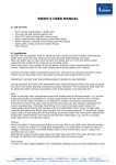
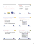
1
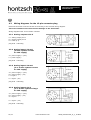
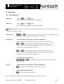
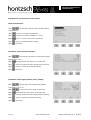
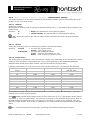
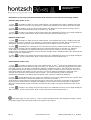
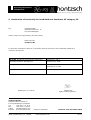
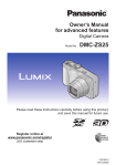
Operating Instructions
flowtherm NT
zertifiziert nach
ISO 9001 : 2008
certified quality
Operating Instructions
flowtherm NT
Software status from 1.03
Multifunctional hand-held unit with data logger for measuring flow rate,
flow velocity, temperature, pressure and other variables
U408_flowthermNT_B_e_110809
www.hoentzsch.com
1/33
Operating Instructions
flowtherm NT
Overview and brief introduction of controls and connections
Thermal sensors TA, TADi
Always connect just one sensor at a time!
Vane wheel sensors FA(R), FT,
FA(R)Di or vortex sensors VA, VAT, VADi
or temperature sensors Pt100
Connector socket cap
Close any connections not in use!
2 analog outputs 0-10 V
analog input 4-20 mA
analog input 0-10 V
Holding magnet
for fixing the unit to
metal surfaces
Measured value display
Input channel 1: name/unit
value
Input channel 2: name/unit
value
Input channel 3: name/unit
value
Function keys
Input channel
and status info
Designation
Switch off
and reset
Function keys
,
,
with variable
functions depending on
operation menu
USB connection type 'B'
for connecting to PC or
adapter plug
Arrow keys (measured value display)
,
: shift between
1, 2 and 3 values
,
: scroll the 3 values
with display of 1 and 2
values
Switch on
ok key (measured value display)
Battery compartment
for 4 batteries / rechargeable batteries Mignon (AA)
: switching the display light on
or off
For settings and other
functions see Section 5
Please ensure that the correct flow sensor (FA, VA or TA) is selected (see under 5.3.19)!
2/33
www.hoentzsch.com
U408_flowthermNT_B_e_110809
Operating Instructions
flowtherm NT
Contents
1 Safety Instructions
1.1
Specific information
1.2
Handling batteries
2 Scope of Delivery
2.1
Description, type plate
3 Technical Specifications
3.1
Operating conditions
3.2
Housing and connection
3.3
Electrical data
3.4
Measuring uncertainty
4 Initial Operation / Startup
4.1
Connector sockets
4.2
Wiring diagram for the 8-pin connector plug
4.3
Wiring diagrams for the 12-pin connector plug
4.3.1
Analog outputs 0-10V
4.3.2
Analog input 4-20 mA
4.3.3
Analog input 0-10 V
5 Operation
5.1
Key functions
5.2
Setup menu after switching on
5.3
Parameter settings
6 Troubleshooting
7 Replacement Parts
8 Instruction Manual Category 3G
9 Declaration of Conformity Category 3G
U408_flowthermNT_B_e_110809
www.hoentzsch.com
3/33
Operating Instructions
flowtherm NT
1
Safety Instructions
Risk of death and injury, and cause of damages.
Read the Operating Instructions carefully before initial operation.
Observe general safety precautions and also those included in other sections of these Operating
Instructions.
Hazard risks:
- non-observance of the Operating and Safety Instructions
- modifications to the device by the customer
- handling the device outside the specified operating conditions
- handling the sensors outside the specified operating conditions
- use of unsuitable power supplies and peripheral devices
- improper use of the device
Prevention of voltage hazards:
- use only the dedicated adapter plug for the mains supply
- make sure that the PC is correctly connected to the mains (earthed safety socket, earthing) when using
a USB connection
- when connecting analog outputs or inputs to peripheral devices make sure that these are correctly
connected to the mains (earthed safety socket, earthing)
Danger when installing the sensors in pressurized pipelines:
- sensors for use in pressurized pipelines are to be inserted or retracted in depressurized conditions only;
non-oberservance may result in serious injuries to personnel
- when installing or removing under pressure, the appropriate protective equipment must be used,
e.g. ball valve and probe guide pieces with chain guard or spindle probe guide pieces
Danger when using the device in explosive atmospheres:
- the unit and its sensors may only be used in areas specified for category 3G (zone 2 gas) equipment
- when sensors with category 1/2 G, 1/2 D or 2 G, 2 D or 3 D markings are connected to the device they
may only be used in category 3G areas! (See also Instruction Manual Category 3G and Declaration
of Conformity in Sections 8 and 9)
1.1 Specific information
- pay heed to the mains voltage when using voltage converters
- observe the maximum power rating when connecting sensors powered by more than 12 V supply
- when operating out of doors make sure that the battery compartment cover and sensor plug are screwed
on tightly, the connector sockets not in use are firmly capped, and the USB connection cover is tightly
sealed, otherwise the IP65 protection cannot be guaranteed
4/33
www.hoentzsch.com
U408_flowthermNT_B_e_110809
Operating Instructions
flowtherm NT
1.2 Handling batteries
- always change / charge all 4 batteries and check for correct polarity
- recharge batteries with a suitable charger away from the unit
- remove batteries when they are dead or if the device is not being used for any length of time
to avoid leakage
- batteries contain hazardous substances and must never be disposed of in household waste
2
-
Scope of Delivery
hand-held unit flowtherm NT
Operating Instructions and Data Sheet flowtherm NT
FA, VA or TA sensor(s) as ordered
relevant Data Sheet for above
other sensors such as Pt100, if ordered
accessories for sensors, e.g. extension rod for FA sensor, if ordered
CD-ROM with PC software HLOG II and USB cable (optional)
adapter plug and USB cable (optional)
various connection and extension cables, connectors (optional)
carrying case (optional)
Please check that everything listed in the Delivery Note / Technical Data Sheet is included in the delivery.
2.1
Description, type plate
The flowtherm NT is a multifunctional hand-held unit with data logger for measuring flow velocity, volume
flow/flow rate, standard flow rate, mass flow, temperature, pressure and other variables, insofar as they
are measurable / deducible with the connectable sensors:
-
vane wheel sensors FA, FAR, FT, FADi, FARDi
vortex sensors VA, VAT, VADi
thermal sensors TA10, TADi
temperature sensors Pt100
2-wire 4-20 mA sensors with 12 V supply
3 or 4-wire 4-20 mA sensors with output and 12 V supply
3 or 4-wire sensors with 0-10 V output and 12 V supply
U408_flowthermNT_B_e_110809
www.hoentzsch.com
5/33
Operating Instructions
flowtherm NT
The following type plate is found on the back of the unit:
1
2
3
4
5
6
7
8
Description of type plate specifications:
6/33
1:
Description
see Section 2.1
2:
Device and serial no.
3:
Marking for Ex-applications category 3G
see Safety Instructions Section 1
see Instruction Manual Category3G Section 8
see Declaration of Conformity Section 9
4:
Inputs
see Description Section 2.1
see Connector sockets Section 4.1
see Wiring diagrams Section 4.2 and 4.3
5:
Outputs
see Electrical data Section 3.3
see Connector sockets Section 4.1
see Wiring diagrams Section 4.3
6:
USB connection
see Electrical data Section 3.3
see Connector sockets Section 4.1
7:
Power supply
see Safety Instructions Section 1
see Electrical data Section 3.3
8:
Operating Conditions
see Safety Instructions Section 1
see Operating conditions Section 3.1
www.hoentzsch.com
U408_flowthermNT_B_e_110809
Operating Instructions
flowtherm NT
3
3.1
Technical Specifications
Operating conditions
Ambient temperature
of the housing when in service
: -20 ... +50 °C
Type of protection
: IP65
3.2
Housing and connection
Type of protection
: IP65 with battery compartment cover and sensor plug screwed on
tightly, connector sockets not in use firmly capped, and USB connection
cover tightly sealed
Material
: electrically conductive ABS plastic
External measurements, weight : W/H/L = 96/42/197 mm, approx. 520 g
Connections
: 5-pin connector plug for thermal sensors
: 8-pin connector plug for vane wheel, vortex or temperature
sensors
12-pin connector plug for analog outputs or inputs
USB for data logger readout, configuration of the device and external
power supply via PC or mains adapter
3.3
Electrical data
Power supply
: via 4 alkaline manganese Mignon (AA) 1.5V batteries
running time (Duracell Plus) approx. 24 hours
(using flow sensor FA without display light)
or via 4 NiMH rechargeable Mignon (AA) 1.2V batteries
running time (Ansmann Digital 2850 mAh) approx 26 hours
(using flow sensor FA without display light)
Open the battery compartment on the back of the device with a screw driver. Always change all 4
batteries at the same time, checking for correct polarity. Only ever recharge batteries away from the unit
using a suitable charger. Always ensure that all 4 rechargeable batteries are fully recharged before inserting. To close the compartment press it firmly in the seal (in the direction of the connector sockets) and
screw down tightly.
Mains supply
Supply current
: via USB connection with PC or adapter plug
: via USB connection not less than 300 mA
The mains supply is not electrically isolated from the outputs.
The "-" connection of the analog outputs and the earth of the USB connection have the same potential, i.e.
for EMC reasons a peripheral device should have potential-free inputs for evaluation of the analog outputs
when connecting to a PC.
Analog outputs (2 x)
U408_flowthermNT_B_e_110809
: 0 ... 10 V with internal resistance of 1000 Ohm
Measured, initial and final values adjustable at any one time
www.hoentzsch.com
7/33
Operating Instructions
flowtherm NT
Analog input 4-20 mA
: for connection of sensors in 2-wire system with ≤ 12 V supply;
allocation of unit, initial value and final value adjustable.
Analog input 0-10 V
: for connection of sensors with voltage output; input resistance 5 MOhm.
≤ 12 V power supply for sensors, max. 100 mA; allocation of unit, initial
value and final value adjustable.
3.4
Measuring Uncertainty
Input FA
: +/- 1 Hz
Input VA
: +/- 1 Hz
Input TA
Temperature display
: +/- 1 (0.7 % of meas. value + 0.02 % of full scale)
: +/- 1 Kelvin
Analog input 0-10 V
: +/- 1 (0.3 % of meas. value + 0.02 % of full scale)
Analog input 4-20 mA
: +/- 1 (0.3 % of meas. value + 0.02 % of full scale)
Input Pt100
: +/- 0.2 Kelvin
Analog output 1+2, 0-10 V
: +/- 1 (0.2 % of meas. value + 0.02 % of full scale)
All values are valid for adjusted damping of 30 seconds while measurement. The measuring uncertainties
of the used sensors have to be considered additionally.
4
Initial Operation / Startup
For installation and operation of the system, especially in category 3G, the national regulations currently
in force, the recognised standards of good practice and these Operating Instructions are decisive.
4.1
Connector sockets
5-pin connector socket:
for thermal sensors TA10 and TADi measuring tubes
8-pin connector socket:
for vane wheel sensors FA, FAR, FT and FADi measuring tubes
for vortex sensors VA, VAT and VADi measuring tubes
for temperature sensors Pt100
Always connect just one sensor at a time!
8/33
www.hoentzsch.com
U408_flowthermNT_B_e_110809
Operating Instructions
flowtherm NT
12-pin connector socket:
for analog outputs 2 x 0-10 V
for analog input 4-20 mA
for analog input 0-10 V
USB connector socket type B
data logger readout, hardware configuration
for external power supply via PC or adapter plug
Always make sure that the connector sockets not in use are firmly capped, the sensor plug is
screwed on tightly and the USB connection cover is tightly sealed, otherwise the IP65 protection
cannot be guaranteed
4.2
Wiring diagram for the 8-pin connector plug
Electrical connection must be carried out according to the relevant wiring diagram.
Incorrect connection can cause serious damage to the electronics.
Wiring diagram with view of solder contacts:
Pin assignment
pin 1: v/FA+FAR signal 1 F or v/VA signal F
pin 2: ground G
pin 3: PT100
pin 4: PT100
pin 5: PT100
pin 6: PT100
pin 7: v/FAR signal 2 F
pin 8: V+
housing: shield
U408_flowthermNT_B_e_110809
www.hoentzsch.com
4
5
2
1
3
8
6
7
9/33
Operating Instructions
flowtherm NT
4.3
Wiring diagrams for the 12-pin connector plug
Electrical connection must be carried out according to the relevant wiring diagram.
Incorrect connection can cause serious damage to the electronics.
Wiring diagrams with view of solder contacts:
4.3.1 Analog outputs 0-10 V
C = analog output port 1
D = analog output port 2
E = earth (0 V)
plug shell = shielding
4.3.2 Analog input 4-20 mA
(2-wire system current
for 12V supply)
A = power supply + (12V)
F = power supply –
plug shell = shielding
4.3.3 Analog input 4-20 mA
(3 or 4-wire system current
for 12V supply)
A = power supply + (12V)
B = power supply – (0V)
F = signal +
H = signal - (0V)
plug shell = shielding
4.3.4 Analog input 0-10 V
(3 or 4-wire system voltage
for 12V supply)
A = power supply + (12V)
B = power supply – (0V)
G = signal +
H = signal – (0V)
plug shell = shielding
10/33
www.hoentzsch.com
U408_flowthermNT_B_e_110809
Operating Instructions
flowtherm NT
5
5.1
Operation
Key functions
Switch on:
with the
key (also
symbol)
hold the key down until text appears in the display.
Switch off:
with the
key (also
symbol)
press the key briefly and wait until the display goes off.
Reset! Should the unit no longer react to key operation, switch off can be enforced by pressing the
off key for more than 10 seconds.
Control keys:
,
and
are control keys with variable functions, which are identified in the
lowermost row of the display depending on operation menu.
Arrow keys:
in the measured value display / view after switch on:
during measured value display the arrow keys have the following function:
and
: shift the display. Definition whether the values from 1, 2 or 3
input channels are displayed simultaneously. Depending on selection, the
character size of the display values changes.
and
: is the display so set that only measured values from 1 or 2
input channels are displayed simultaneously, then scrolling with these keys
through the input channels can be carried out.
In the menus and input boxes:
,
,
and
are control keys for navigating within the various menus
and menu levels.
ok key:
In the measured value display / view after switch on:
is a control key for switching the display light on or off.
In the menus and input boxes:
is a control key to select and save.
Refer to the following examples for a detailed description of the respective functions.
U408_flowthermNT_B_e_110809
www.hoentzsch.com
11/33
Operating Instructions
flowtherm NT
Examples for key functions in the menus:
Menu selection list:
With
up or down in the list; the selected element
is highlighted.
With
a menu level higher (backwards).
With
a menu level lower (forwards) = select.
With
select = a menu level lower (forwards).
With
return to measured value display.
With
switch off.
Parameter value selection window:
With
new selection element; the selected element
flashes (here "mn").
With
select and save and return to selection list.
With
return to measured value display without saving.
With
return to selection list without saving.
With
switch off.
Parameter value digit (numeric/text) setting:
With
change digit; the selected and editable
digit flashes (here "1").
With
1 digit to the left or right respectively.
With
select and save and return to selection list.
With
return to measured value display without saving.
With
return to selection list without saving.
With
switch off.
12/33
www.hoentzsch.com
U408_flowthermNT_B_e_110809
Operating Instructions
flowtherm NT
5.2 Setup menu after switch on:
Menu
LM-Start
Settings
Logger
Off
Reset
5.3.24
Sensor
5.3.25
FA input
Basic settings 5.3.1
Type 5.3.1.1
Range 5.3.1.2
Material 5.3.1.3
Directional sensing 5.3.1.4
Measurement settings 5.3.2
Medium 5.3.2.1
Section 5.3.2.2
Profile factor 5.3.2.3
Density correction 5.3.3
Display 5.3.4
Damping 5.3.4.1
Unit 5.3.4.2
Pairs of values 5.3.5
View 5.3.21.1
Settings 5.3.21.2
Delete 5.3.21.3
VA input
Basic settings 5.3.6
Type 5.3.6.1
Measurement settings 5.3.7
Section 5.3.7.1
Profile factor 5.3.7.2
Display 5.3.8
Damping 5.3.8.1
Unit
5.3.8.2
Pairs of values 5.3.9
TA input
Basic settings 5.3.10
Type 5.3.10.1
Measurement settings 5.3.11
Section 5.3.11.1
Profile factor 5.3.11.2
Display 5.3.12
Damping 5.3.12.1
Unit 5.3.12.2
Pairs of values 5.3.13
PT100 input
Unit 5.3.14
Analog input 5.3.15
Output 5.3.16
Port 5.3.16.1
Source 5.3.16.2
Display values 5.3.17
Rows 5.3.17.1
Row 1 5.3.17.2
Row 2 5.3.17.3
Row 3 5.3.17.4
Long-term measurement 5.3.18
Mode 5.3.18.1
Device 5.3.19
Factory settings 5.3.20
Data logger 5.3.21
View 5.3.21.1
Settings 5.3.21.2
Delete 5.3.21.3
Status 5.3.22
Profiles 5.3.23
Switch off 5.3.25
U408_flowthermNT_B_e_110809
www.hoentzsch.com
13/33
Operating Instructions
flowtherm NT
5.3 Parameter settings
Settings for vane wheel sensors FA:
5.3.1
Menu -> Settings -> Sensor -> FA input -> Basic settings
The connected vane wheel sensor determines the parameter type, measuring range, material and directional sensing to be set.
5.3.1.1
Type
Setting the vane wheel type:
The vane wheel type can be determined from the serial no. on the sensor.
Selection:
5.3.1.2
mc
=
mn
=
md
=
md3
=
pairs of values
=
vane wheel type micro for use in e.g.:
cylinder probes with OD 14, 16, 18 mm
measuring tubes with ID 9.7 mm
vane wheel type mini for use in e.g.:
cylinder probes with OD 25 mm
measuring tubes with ID 18.2 mm
vane wheel type midi for use in e.g.:
cylinder probes with OD 30 mm
vane wheel type midi md3 for use in e.g.:
cylinder probes with OD 30 mm, optimized
for velocities up to max. 3 m/s
special calibration characteristic specifically matched to the
measuring task based on up to 30 supporting points. Entering or
changing the points, see under 5.3.5.
Measuring range
Setting the vane wheel measuring range:
The measuring range can be determined from the serial no. on the sensor.
Selection:
20
40
80
120
=
=
=
=
measuring
measuring
measuring
measuring
range
range
range
range
up
up
up
up
to
to
to
to
20 m/s
40 m/s
80 m/s
120 m/s
The measuring range must not be exceeded; otherwise the vane wheel can be permanently
damaged!
5.3.1.3
Material
Setting the vane wheel sensor material:
The material can be determined from the serial no. on the sensor.
Selection:
5.3.1.4
steel
aluminium
titanium
=
=
=
E
A
T
Directional sensing
Setting for the directional sensing function:
Such sensors can be identified by an "R" in the serial number.
Selection:
14/33
Y
N
= directional sensing yes, measured value display with prefix
= directional sensing no, measured value display without prefix
www.hoentzsch.com
U408_flowthermNT_B_e_110809
Operating Instructions
flowtherm NT
5.3.2
Menu -> Settings -> Sensor -> FA Input -> Measurement settings
The measuring task to be carried out determines the parameter medium, section and profile factor to be
set here for the vane wheel sensor.
5.3.2.1
Medium
Setting the medium:
Should pairs of values or md3 be selected in the basic settings (5.3.1.1), this setting has no impact on the
measurement.
Selection:
G
F
= Gases, the characteristic for air/gases is applied
= Liquids (Fluids), the characteristic for water/liquids is applied
Only vane wheel sensors "GF" may be used in liquids; otherwise the sensor can be permanently
damaged!
5.3.2.2
Section
Setting the measuring section for measuring in pipelines for flow rate display:
Selection:
Circular
Rectangular
5.3.2.3
= for pipes
di/mm:
= for pipes
a/mm:
b/mm:
with circular section
enter the ID in mm
with rectangular section
enter the inner surface a in mm
enter of the inner surface b in mm
Profile factor
The profile factor PF specifies the ratio of mean flow velocity in the measuring section and the flow velocity
measured from the sensor. Requirements are: centric sensor positioning, non-rotational inlet flow and
adequate dimensioned input/output sections. (See also Documents U117 and U205)
Following profile factors are to be set for vane wheel cylinder probes (ZS..) according to pipe diameter:
Pipe ID
in mm
40
50
60
70
80
90
100
120
170
180
220
...
PF for ZS16 (mc)
PF for ZS18 (mc)
0.914
0.933
0.950
0.964
0.976
0.987
0.994
1.004
1.008
1.008
1.008
1.008
0.898
0.916
0.932
0.948
0.962
0.975
0.986
1.004
1.021
1.021
1.021
1.021
PF for ZS25 (mn) and ZS30
(md and md3)
0.735
0.760
0.784
0.807
0.829
0.849
0.882
0.935
0.945
0.955
0.955
For measuring in larger free jet as well as larger ducts or measuring tubes, with setting PF = 1.000 the
local/punctual velocity will be displayed.
With
TABLE a profile factor subject to the set vane wheel type (5.3.1.1) and diameter of the measuring surface (5.3.2.2) is recommended. This value can be verified or also amended before saving. With rectangular selected as measuring surface, the surface is converted to circular for the proposed value and
this value is approximate. If the sensor is a ZS18 (mc), the value must be corrected according to the table
above.
PF = 1.000 must always be set for FADi.. measuring tubes calibrated with pairs of values!
U408_flowthermNT_B_e_110809
www.hoentzsch.com
15/33
Operating Instructions
flowtherm NT
5.3.3
Menu -> Settings -> Sensor -> FA Input -> Density correction
Liquids:
Liquids are virtually density resistant. No density correction needed.
Gases and vapours:
The density of gases and vapours can be strongly modified against pressure and temperature. Such a severe
modification leads to a minor impact on the measured value of a vane wheel sensor. This impact
manifests itself in a determinable correction value, which is added to or subtracted from the measured value.
The percentaged impact of this correction value is however negligible with average to high velocity flow. With
low and very low values, consideration of the density correction becomes more expediant.
To determine this correction value the measuring range initial value (starting value) of a vane wheel is
examined. The specified starting value in the vane wheel sensor documents arises from a medium density of
1.204 kg/m³ (calibration conditions). The only slightly deviating actual starting value, even with considerably
different working density of the medium (in the actual application) ensues in good approximation of the
following:
actual starting value = specified starting value x root of (density during calibration / working density of the
medium).
The correction value is now the difference between the real and the specified starting value. The
characteristic of the sensor is displaced by this value.
If the operating density of the medium is greater than the calibration density of 1.204 kg/m³, then the
determined correction value must be deducted from the measured value. If it is less than the calibration
density of 1.204 kg/m³, then the determined correction value must be added to the measured value.
The working medium density is needed to calculate the correction value.
Example:
A ZS25GE-mn40/100/p10 sensor with a specified starting value of 0.5 m/s is used in air at 1.013 bar and
100 °C, i.e. with a working medium density of 0.946 kg/m³.
Entered in formula:
actual starting value
correction value
= 0.5 m/s x root of (1.204 kg/m³ / 0.946 kg/m³) = 0.5 m/s x 1.128
= 0.564 m/s
= 0.564 m/s – 0.5 m/s
= 0.064 m/s
With a displayed value of 15.00 m/s (without correction) and with density correction on, the correction value of
0.064 m/s would be allowed for and a corrected value of 15.06 m/s would be displayed.
Setting:
Selection:
N
Y
= density correction no
= density correction yes
W-density/kg/m3:
then enter the density of the sample gas:
enter the working medium density in kg/m³
If the working medium density is not known, it can be determined with the formula:
W-density = P / (R * T)
where P = absolute pressure in Pa, R = specified gas constant in J/(kg*K), T = temperature in K.
Here the specified gas constants of some gases:
sample gas
dry air
steam H2O
argon Ar
carbon dioxide CO2
carbon monoxide CO
helium He
16/33
spec. gas constant
in J/(kg*K)
287
462
208
189
297
2077
sample gas
hydrogen H2
methane CH4
nitrogen N2
oxygen O2
propane C3H8
sulphur dioxide SO2
www.hoentzsch.com
spec. gas constant
in J/(kg*K)
4124
518
297
260
189
130
U408_flowthermNT_B_e_110809
Operating Instructions
flowtherm NT
5.3.4
Menu -> Settings -> Sensor -> FA input -> Display
The parameters damping and unit to be set here affect the measured value display, when FA is selected as
sensor (see 5.3.19). Damping affects the analog output, if FA is selected as the source (see 5.3.16).
5.3.4.1
Damping
Damping/s: enter the damping time of 01 to 99 seconds
Example 10 seconds: after every second the arithmetical average of the last 10 seconds is displayed.
5.3.4.2
Unit
Selection of the unit for measured value display and data logger
Selection:
5.3.5
m/s
= flow velocity in meter / second
ft/min
= flow velocity in feet / minute
m3/h
= flow rate in m³/ hour calculated from flow velocity
and entered measured section (see 5.3.2.2)
l/s
= flow rate in litre / second calculated from flow velocity and
entered measured section (see 5.3.2.2)
l/min
= flow rate in litre / minute calculated from flow velocity
and entered measured section (see 5.3.2.2)
cfm
= flow rate in cubic feet / minute calculated from flow velocity
and entered measured section (see 5.3.2.2)
kg/h
= mass flow in kg / hour calculated from flow velocity and entered
measured section (see 5.3.2.2), the measured or entered working
temperature and working pressure, and the entered standard
density (standard conditions: 0 °C and 1013 hPa).
With the selection "measure" for temperature and pressure
the respective input channel must be selected and set (see 5.3.15)
N-m3/h
= standard flow rate in standard-m³ / hour calculated from flow velocity
and entered measurement section (see 5.3.2.2), measured or entered
working temperature and pressure
(standard conditions: 0 °C and 1013 hPa).
With the selection "measure" for temperature and pressure the
respective input channel must be selected and set (see 5.3.15)
Menu -> Settings -> Sensor -> FA Input -> Pairs of values
If pairs of values is selected (see 5.3.1.1), then the here alterable values for determining the measured
value are applied as a calibration curve.
Selection:
Configuration
= enter the quantity of pairs of values (maximal 30) for
processing and display
Pairs of values
= display and change of pairs of values.
A pair of values always consists of a velocity value in m/s
and a frequency value in Hz.
The condition being: the pairs of values must be ever
increasing, i.e. the next velocity or frequency value must always
be greater than the previous one.
U408_flowthermNT_B_e_110809
www.hoentzsch.com
17/33
Operating Instructions
flowtherm NT
Example for quantity = 03
01:000.50m/s, 00010Hz
02:010.00m/s, 00350Hz
03:040.00m/s, 01770Hz
If the frequency measured value is greater than in the last pair of values, then the velocity value is
calculated. However, this means that the measurement uncertainty increases as this value is then outside
the calibrated range. With vane wheel sensors, the measuring range found in the serial no. and technical
data sheet must not be exceeded, as this may cause permanent damage to the vane wheel! (For further
information refer to 5.3.1.2/Page 13 of these Operating Instructions).
Settings for vortex sensors VA:
5.3.6
Menu -> Settings -> Sensor -> VA Input -> Basic settings
The connected vortex sensor determines the parameter type.
5.3.6.1
Type
Setting the type of vortex sensor:
Refer to the relevant technical documents for selection options.
Selection:
KKZ
=
the calibration number (KKZ) is individually determined for each
sensor and modifies the basic characteristics.
KKZ: enter as an 8-digit figure, in which each digit has a
0..9..A..F range (hexadecimal = 16 possible variables).
The actual KKZ can be found in the technical data sheet, calibration
certificate or directly on the sensor
pairs of values = special calibration characteristic specifically matched to the
measuring task based on up to 30 supporting points. Entering or
changing the points, see under 5.3.9.
The actual pairs of values are documented in the technical
documents.
5.3.7
Menu -> Settings -> Sensor -> VA Input -> Measurement settings
The measuring task to be carried out determines the parameter section and profile factor to be set here
for the vortex sensor.
5.3.7.1
Section
Setting the measuring section for measuring in pipelines for flow rate display:
Selection:
Circular
Rectangular
18/33
= for pipes
di/mm:
= for pipes
a/mm:
b/mm:
with circular section
enter the ID in mm
with rectangular section
enter the inner surface a in mm
enter the inner surface b in mm
www.hoentzsch.com
U408_flowthermNT_B_e_110809
Operating Instructions
flowtherm NT
5.3.7.2
Profile factor
The profile factor PF specifies the ratio of mean flow velocity in the measuring section and the flow velocity
measured from the sensor. Requirements are: centric sensor positioning, non-rotational inlet flow and
adequate dimensioned input/output sections. (See also Documents U155 and U206).
Following profile factors are to be set for vortex sensors VA40 subject to the pipe diameter:
Pipe ID
in mm
80
90
100
110
120
130
140
150
PF for VA40
0.719
0.729
0.738
0.750
0.761
0.773
0.784
0.796
Pipe ID
in mm
160
170
180
190
200
300
400
...
PF for VA40
0.808
0.819
0.830
0.839
0.842
0.845
0.850
0.850
For measuring in larger free jet as well as larger ducts or measuring tubes with setting PF = 1.000 the
local/punctual velocity will be displayed.
With
TABLE a profile factor subject to the set diameter of the measuring surface (5.3.7.1) is recommended. This value can be verified or also amended before saving. With rectangular selected as measuring surface, the surface is converted to circular for the proposed value and this value is approximate.
PF = 1.000 must always be set for VADi.. measuring tubes calibrated with pairs of values!
5.3.8
Menu -> Settings -> Sensor -> VA Input -> Display
The parameters damping and unit to be set here affect the measured value display, when VA is selected
as sensor (see 5.3.19). Damping affects the analog output, if VA is selected as the source (see 5.3.16).
.
5.3.8.1
Damping
Damping/s:
enter the damping time from 01 to 99 seconds
Example 10 seconds: after every second the arithmetical average from the last 10 seconds is displayed.
U408_flowthermNT_B_e_110809
www.hoentzsch.com
19/33
Operating Instructions
flowtherm NT
5.3.8.2
Unit:
Selection of the unit for the measured value display and data logger
Selection:
5.3.9
m/s
= flow velocity in meter / second
ft/min
= flow velocity in feet / minute
m3/h
= flow rate in m³/ hour calculated from flow velocity
and entered measured section (see 5.3.7.1)
l/s
= flow rate in litre / second calculated from flow velocity and
entered measured section (see 5.3.7.1)
l/min
= flow rate in litre / minute calculated from flow velocity
and entered measured section (see 5.3.7.1)
cfm
= flow rate in cubic feet / minute calculated from flow velocity
and entered measured section (see 5.3.7.1)
kg/h
= mass flow in kg / hour calculated from flow velocity and entered
measured section (see 5.3.7.1), the measured or entered
working temperature and working pressure, and the entered standard
density (standard conditions: 0 °C and 1013 hPa).
With the selection "measure" for temperature and pressure
the respective input channel must be selected and set (see 5.3.15)
N-m3/h
= standard flow rate in standard-m³ / hour calculated from flow velocity
and entered measured section (5.3.7.1), measured or entered
working temperature and pressure
(standard conditions: 0 °C and 1013 hPa).
With the selection "measure" for temperature and pressure the
respective input channel must be selected and set (see 5.3.15)
Menu -> Settings -> Sensor -> VA Input -> Pairs of values
If pairs of values is selected (see 5.3.6.1), then the here alterable pairs of values for determining the
measured value is applied as a calibration curve.
Selection:
Configuration
= enter the quantity of pairs of values (maximal 30) for
processing and display
Pairs of values
= display and change of pairs of values.
A pair of values always consists of a velocity value in m/s
and a frequency value in Hz.
The condition being: the pairs of values must be ever
increasing, i.e. the next velocity or frequency value must always
be greater than the previous one.
Example for quantity = 03
01:000.50m/s, 00010Hz
02:010.00m/s, 00350Hz
03:040.00m/s, 01770Hz
If the frequency measured value is greater than in the last pair of values, then the velocity value is
calculated. However, this means that the measurement uncertainty increases as this value is then outside
the calibrated range.
20/33
www.hoentzsch.com
U408_flowthermNT_B_e_110809
Operating Instructions
flowtherm NT
Settings for thermal sensors TA:
5.3.10
Menu -> Settings -> Sensor -> TA Input -> Basic settings
The connected thermal sensor determines the parameter type.
5.3.10.1
Type
Setting the type of thermal sensor:
Refer to the relevant technical documents for selection options.
Selection:
KKZ
=
the calibration number (KKZ) is individually determined for each
sensor and modifies the basic characteristics.
KKZ: enter as a 14-digit figure, in which each digit has a
0..9..A..F range (hexadecimal = 16 possible variables).
The actual KKZ can be found in the technical data sheet, calibration
certificate or directly on the sensor
pairs of values = special calibration characteristic specifically matched to the
measuring task based on up to 30 supporting points. Entering or
changing the points, see under 5.3.13.
The actual pairs of values can be found in the technical documents.
5.3.11
Menu -> Settings -> Sensor -> TA Input -> Measurement Settings
The measuring task to be carried out determines the parameter section and profile factor to be set here
for the thermal sensor.
5.3.11.1
Section
Setting the measuring section for measuring in pipelines for flow rate display:
Selection:
Circular
Rectangular
5.3.11.2
= for pipes
di/mm:
= for pipes
a/mm:
b/mm:
with circular section
enter the ID in mm
with rectangular section
enter the inner surface a in mm
enter the inner surface b in mm
Profile factor
The profile factor PF specifies the ratio of mean flow velocity in the measuring section and the flow velocity
measured from the sensor. Requirements are: centric sensor positioning, non-rotational inlet flow and
adequate dimensioned input/output sections. (See also Documents U232 and U234).
Following profile factors are to be set for thermal flow sensors TA10 subject to the pipe diameter:
Pipe ID
in mm
25
27.2
35.9
40
41.8
50
...
PF for thermal
sensors TA10
0.725
0.740
0.790
0.810
0.820
0.840
0.840
For measuring in larger free jet as well as larger ducts or measuring tubes with setting PF = 1.000 the
local/punctual velocity will be displayed.
U408_flowthermNT_B_e_110809
www.hoentzsch.com
21/33
Operating Instructions
flowtherm NT
with
TABLE a profile factor subject to the set diameter of the measuring surface (5.3.11.1) is recommended. This value can be verified or also amended before saving. With rectangular selected as measuring surface, the surface is converted to circular for the proposed value and this value is approximate.
PF = 1.000 must always be set for TADi.. measuring tubes calibrated with pairs of values!
5.3.12
Menu -> Settings -> Sensor -> TA Input -> Display
The parameters damping and unit to be set here affect the measured value display, when TA is selected
as sensor (see 5.3.19). Damping affects the analog output, if TA is selected as the source (see 5.3.16).
5.3.12.1
Damping
Damping/s:
enter the damping time of 01 to 99 seconds
Example 10 seconds: after every second the arithmetical average of the last 10 seconds is displayed.
5.3.12.2
Unit:
Selection of the unit for the measured value display and data logger
Selection:
N-m/s
= standard flow velocity in meter / second
(standard conditions: 21°C and 1014 hPa).
N-ft/min = standard flow velocity in feet / minute
(standard conditions: 21°C and 1014 hPa).
22/33
N-m3/h
= standard flow rate in m³/ hour calculated from flow velocity and
entered measured section (see 5.3.11.1)
(standard conditions: 21°C and 1014 hPa).
N-l/s
= standard flow rate in litre / second calculated from flow velocity and
entered measured section (see 5.11.1)
(standard conditions: 21°C and 1014 hPa).
N-l/min
= standard flow rate in litre / minute calculated from flow velocity and
entered measured section (see 5.3.11.1)
(standard conditions: 21°C and 1014 hPa).
N-cfm
= standard flow rate in cubic feet / minute calculated from flow velocity
and entered measured section (see 5.3.11.1)
(standard conditions: 21°C and 1014 hPa).
kg/h
= mass flow in kg / hour calculated from flow velocity and entered
easured section (see 5.3.11.1) and entered standard density
(standard conditions: 21°C and 1014 hPa).
www.hoentzsch.com
U408_flowthermNT_B_e_110809
Operating Instructions
flowtherm NT
5.3.13
Menu -> Settings -> Sensor -> TA Input -> Pairs of values
If pairs of values is selected (see 5.3.10.1), then the here alterable pairs of values for determining the
measured value is applied as a calibration curve.
Selection:
Configuration
= enter the quantity of pairs of values (maximal 30) for
processing and display
Pairs of values
= display and change of the pairs of values.
A pair of values always consists of a velocity value in m/s
and a frequency value in Hz.
The condition being: the pairs of values must be ever
increasing, i.e. the next velocity or frequency value must always
be greater than the previous one.
Example for quantity = 03
01:000.50m/s, 06000Hz
02:010.00m/s, 08350Hz
03:040.00m/s, 12770Hz
If the frequency measured value is greater than in the last pair of values, the the velocity value is
calculated. However, this means that the measurement uncertainty increases as this value is then outside
the calibrated range.
Note: For switching between different calibration gases with a thermal sensor each pair of values
calibration for the respective calibration gas can be saved in its own device profile (see 5.3.23)
Resetting the factory settings (see 5.3.20) has no impact on the saved profile. Changing the pairs
of values for the various calibration gases can only be reconstructed via the documentation in the Technical Data Sheet and calibration certificate.
U408_flowthermNT_B_e_110809
www.hoentzsch.com
23/33
Operating Instructions
flowtherm NT
Settings for the Pt100 input for temperature measurement:
5.3.14
Menu -> Settings -> Sensor -> PT100 Input -> Unit
The parameter unit to be set here affects the measured value display
Selection:
°C
= display of temperature in °C
°F
= display of temperature in °F
Settings for the analog inputs:
5.3.15
Menu -> Settings -> Sensor -> Analog input
Input:
Selection:
4-20mA = current input 4-20 mA is selected
0-10V
= voltage input 0-10 V is selected
Designation:
for each of the two inputs a designation of up to 13 digits for the sensor can
be entered.
Example: pressure sensor
Equivalent:
for each of the two inputs a display equivalent can be defined. For this
purpose the desired initial value at 4 mA or 0 V and the desired final value at
20 mA or 10 V is entered respectively.
Example: 4 ... 20 mA -> 900 ... 1600 hPA
Unit:
for each of the two inputs a unit of up to 5 digits for measured value display
can be entered.
Example: hPa
(unused digits are marked with a "*" and are not shown in the display
and data logger)
Settings for the analog outputs:
5.3.16
Menu -> Settings -> Output
Settings for both analog output ports 1 and 2
5.3.16.1
Port
Selection of the analog output port 1 or 2. Setting of the selected port under (5.3.16.2)
5.3.16.2 Source
Setting the source and the measured value-equivalent for the analog output port selected under
(5.3.16.1).
Selection:
FA, VA, TA
= flow sensor depending on selection under (5.3.19)
Equivalent:
Pt100
= temperature sensor Pt100
Equivalent:
24/33
initial value analog output at 0 V in m/s
final value analog output at 10 V in m/s
example:
0 ... 10 V -> 0 ... 40 m/s
or:
0 ... 10 V -> 5 ... 20 m/s
initial value analog output at 0 V in °C
final value analog output at 10 V in °C
example: 0 ... 10 V -> -20 ... +100 °C
www.hoentzsch.com
U408_flowthermNT_B_e_110809
Operating Instructions
flowtherm NT
Settings for display values:
5.3.17
Menu -> Settings -> Display values
Settings for the display values. Determining the quantity of the simultaneously displayed values / input
channels and the allocation of these values to the 3 input channels.
5.3.17.1
Rows
The number of rows determines in how many input channels (1, 2 or 3) the measured values are
displayed simultaneously after switch on.
5.3.17.2
Row 1
Selection of which measured value is allocated to input channel 1 and displayed as Row 1.
Selection:
5.3.17.3
Date
= display of the actual date
Time
= display of the actual time
FA, VA, TA input
= display of the flow sensor
depending on selection (see 5.3.19)
Pt100 input
= display of the temperature sensor Pt100
20mA input
= display of the analog input 4-20 mA
10V input
= display of the analog input 0-10 V
TAT input
= display of the temperature measurement of the thermal
sensor TA (only relevant if a TA sensor is selected under 5.3.19)
Row 2
Selection of which measured value is allocated to input channel 2 and displayed as Row 2.
Selection:
5.3.17.4
(see 5.3.17.2)
Row 3
Selection of which measured value is allocated to input channel 3 and displayed as Row 3.
Selection:
(see 5.3.17.2)
Settings for long-term measurement:
5.3.18
Menu -> Settings -> Long-term measurement
Settings for long-term measurement
5.3.18.1
Mode
Setting the measuring mode for long-term measurement
Selection:
Start/Stop
= Start/Stop mode for long-term measurement
Start
= Start mode long-term measurement
also enter:
interval/s = length of measurement in seconds
Auto
= Automatic mode for long-term measurement
also enter:
interval/s = length of measurement in seconds
repitition = amount of repititions
Single measure
= single mode with averaging via the single saved values
U408_flowthermNT_B_e_110809
www.hoentzsch.com
25/33
Operating Instructions
flowtherm NT
Description of the long-term measurement with selection of the various measuring modes:
LM Start/Stop mode is set:
1. press
LM-START to start long-term measurement. The instantaneous value is displayed and the
measurement period in seconds (e.g. S00010) is continuously displayed in the status field (above right).
2. press
LM-STOP to stop long-term measurement, the display is frozen and the average value is
displayed above the measurement period in seconds (e.g. S00030).
3. press
LM-OK to exit display of the average value, the instantaneous value is once again displayed
and is ready for a new measurement. Start a new measurement as described under 1.
LM Start mode is set:
1. press
LM-START to start long-term measurement. The instantaneous value is displayed and the
measurement period in seconds (e.g. S00010) is continuously displayed. The bar above the control key
description shows the progress of the measurement period in relation to the set interval.
LM-STOP before reaching the set interval and long-term measurement stops, the display is
2. press
frozen and the average value is displayed above the measurement period in seconds (e.g. S00020).
If LM-STOP is not activated, the measurement period runs up to the set interval, then long-term
measurement is stopped, the display is frozen and the average value is displayed above the measurement
period in seconds (e.g S00030).
3. press
LM-OK to exit display of the average value, the instantaneous value is once again displayed
and is ready for a new measurement. Start a new measurement as described under 1.
LM Automatic mode is set:
1. press
LM-START to start the long-term measurement. In the 1st interval the instantaneous value
is displayed and the measurement period in seconds (e.g. S00010) is continuously displayed in the status
field (above right). The number of repetitions (R00001) is displayed under it. The bar above the control
key description shows the progress of the measurement period in relation to the set interval. Ater the 1st
interval has elapsed the display is frozen and the next interval starts automatically. Displayed is the
average of the previous interval during the set length. The measurement period in seconds is
continuously displayed in the status field and below it the number of repititions (R00002), ...
2. press
LM-AUTO before the set number of repetitions of long-term measurement are reached, then
long-term measurement is cancelled and waits for a new entry as under 1.
If LM-AUTO is not activated, the measurement period runs to the end of the set number of the intervals,
then long-term measurement is stopped, the display is frozen and the last average value is displayed
above the measurement period in seconds, and below it the number of expired repetitions of the of the
interval.
3. press
LM-OK to exit display of the average value, the instantaneous value is once again displayed
and is ready for a new measurement. Start a new measurement as described under 1.
With data logger on (see 5.3.21.2), in the 3 modes described above, the displayed average is saved
to the data logger with time stamp after each progess of an interval.
26/33
www.hoentzsch.com
U408_flowthermNT_B_e_110809
Operating Instructions
flowtherm NT
SM single measurement mode is set:
SM + displayed instantaneous value is buffered as a single measurement and the
1. by pressing
number of the buffered values (e.g. +00010) is displayed in the status field (above right).
2. by pressing
SM / the average value of the buffered single measurements is calculated and
shown on the frozen display and the number of single measurements used for averaging are displayed in
the status field.
SM-OK display of the average value is exited, the instantaneous value is once again
3. by pressing
displayed and is ready for a new measurement. Start a new measurement as described under 1.
Is the data logger on (see 5.3.21.2), then the average is saved to the data logger with time stamp
by pressing
SM /.
Settings for the device:
5.3.19
Menu -> Settings -> Device
The parameter to be set here affects the flowtherm NT
Selection:
Date: = setting the actual date
Time: = setting the actual time
When changing the batteries the date and time are buffered for several
hours.
Supply:
= battery:
4 Alkali-Mangan Mignon (AA)
rechargeable: 4 NiMh Mignon (AA)
this setting exerts influence on the battery charging level display
Light:
= display light On or Off after switching on the device
Language:
= selection of the dialogue language German or English
Sensor:
= selection of the flow sensor
FA: = vane wheel sensor FA
VA: = vortex sensor VA
TA: = thermal sensor TA
Only ever connect the selected sensor!
Factory settings:
5.3.20
Menu -> Settings -> Factory settings
The flowtherm NT is reset to factory settings, all settings are lost if they have not been previously saved
to a profile of its own (see 5.3.23)
The factory settings are preset as those found in the shipping documents. The values of customer or
application-specific measuring tasks are defined in the documents.
Before resetting to factory settings the following confirmation prompt appears:
Factory setting?
Confirm with
. Cancel with
or
MESS.
Before resetting to factory settings save the actual settings to a profile (see 5.3.23), otherwise they
will be lost.
Cancelling the factory settings does not affect the saved profile.
U408_flowthermNT_B_e_110809
www.hoentzsch.com
27/33
Operating Instructions
flowtherm NT
Data logger:
5.3.21
Menu -> Data logger or
LOGGER
The data logger is for saving measured values generated in various measuring modes of long-term or single measurement (see 5.3.18.1). The contents of the data logger can be viewed on the device or downloaded, saved and subsequently processed via the USB port on a Windows PC with help of the optional
HLOG II software.
The measured values, defined under (5.3.17) for rows 1...3 are saved to the data logger. Date and time
are not logged separately, if these have been selected for measurement display.
Note: In this way the possible number of data records to be logged can be increased, as the length of the
data record is thus reduced. This has no impact on the time stamp for the logged values.
5.3.21.1
View
The contents of the data logger are shown on the display:
With
to the next data set
With
back to menu
With
or
5.3.21.2
Settings
MESS back to measured value display
Settings for the data logger:
Selection:
Data logger: = On or Off
Switch data logger on or off
With data logger on the data for long-term measurement
(see 5.3.18) is saved to the data logger
The data logger can also be switched on from the measured value
display with
or with
Designation: =
5.3.21.3
LOGGER (via Selection: Settings -> Data logger)
LOGGER-OFF switched off.
freely adjustablee measuring point designation with max. 8 digits for
all subsequently saved data logger values until entering a new measuring
point designation.
Delete
Delete the contents of the data logger:
Before deleting a prompt appears:
Delete data logger?
Confirm with
. Cancel with
or
MESS.
All the values saved to the data logger are deleted accordingly.
Before deleting the data logger contents these should be downloaded and saved via the USB port to
a Windows PC with the help of the optional HLOG II software, otherwise they will be lost.
28/33
www.hoentzsch.com
U408_flowthermNT_B_e_110809
Operating Instructions
flowtherm NT
Device status:
5.3.22
Menu -> Status
Display of status:
Software:
= software versions
S.No.:
= serial no.
Memory/%: = display of the free space for the data logger in %
Battery/%: = display of the battery capacity in %
"0" is displayed when supply is via the USB connection.
When the battery symbol appears for the first time on the top right in the measured
value display there is still approx. 10 % battery capacity available.
When using rechargeable batteries "rechargeable" must be selected in the settings (5.3.19) otherwise the battery capacatity display will be incorrect!
Device profiles:
5.3.23
Menu -> Profiles
In the profiles the complete parameter inputs of the device can be saved under a freely definable name
with up to 8 characters and subsequently reloaded.
For example, all parameter entries for a specific sensor can be saved to a profile or also to an appointed
measuring point.
Up to 100 different profiles can be saved. Available profile storage locations are marked with a * behind
the profile name. Profiles cannot be deleted but may be overwritten.
Returning to the factory settings (5.3.20) has no impact on the saved profiles.
Selection:
Load:
= loading a saved profile by selecting from the list
Save:
= saving the active parameter settings to a profile by selecting from the
list in an available profile storage field and entry of a new name or in
an already occupied profile storage location by overwriting and changing
or retaining the name
Keys:
5.3.24
LM-Start
Funktion key for operating the long-term measurement (see 5.3.18)
5.3.25
Switch off / OFF (reset)
Funktion key for switching off the device; active in all menus.
If the device no longer reacts to keypad entry, press this key for more than 10 seconds to switch off the
device and reset.
U408_flowthermNT_B_e_110809
www.hoentzsch.com
29/33
Operating Instructions
flowtherm NT
6
Troubleshooting
Fault
Cause
Troubleshooting
Device cannot be
switched on
Dead batteries
Insert new / re-charged batteries
Faulty electronics
Sensor contaminated
Return to Höntzsch
Clean according to instructions
Profile factor set at 0.000
Set profile factor to the corresponding value of
nominal diameter and sensor type
Unit setting (5.3.19) does
not correspond to the connected flow sensor
Output setting does not
match the port or source
(5.3.16)
Sensor type or KKZ set incorrectly
Adjust the setting (5.3.19) to the connected
sensor or connect compatible sensor
Sensor contaminated
Clean according to instructions
Profile factor set too low
Set profile factor to the corresponding value of
nominal diameter and sensor type
Input/output section too
short
Change sensor position; improve flow
conditions with a flow rectifier
Rotational flow
Reposition sensor in flow direction; use flow
rectifier
Vortex VA sensors:
reduced acoustic coupling in
the sensor elements as a
result of vibration or impact
Sensor type or KKZ set
incorrectly
Return sensor to Höntzsch for checking
Incorrect scaling of analog
output
Check settings and amend if necessary
Profile factor set too high
Set profile factor to the corresponding value of
nominal diameter and sensor type
EMC problem
See reference to electromagnetic compatibility
(EMC) in the sensor documents
No measured value
display or
analog output = 0V
no value
Analog output = 0V
no value
Measured value too
low
Measured value too
high
7
-
Amend output setting port or source (5.3.16)
Compare and correct settings according to
details in the Technical Data Sheet
Compare and correct settings according to
details in the Technical Data Sheet
Replacement Parts
upper housing with keypad
lower housing
battery compartment cover
seal for upper housing
connector socket cap
USB connection cover
12-pin connector plug
30/33
www.hoentzsch.com
U408_flowthermNT_B_e_110809
Operating Instructions
flowtherm NT
8
Instruction Manual Category 3G
8.1
flowtherm NT
Equipment
Hand-held unit flowtherm NT for connection of vane wheel flow sensors FA as probe and measuring tube,
vortex flow sensors VA40 or VADi, thermal flow sensors TA10 or TADi, as well as temperature probes
Pt100.
Use in compliance with regulations
The flowtherm NT with above-mentioned Ex-version category 3G sensors is used for measuring the flow
velocity, the volume flow and the temperature of gases, and also of liquids with specified vane wheel flow
sensors FA and Pt100. It is designed for application in areas in which category 3G equipment is required.
During normal operation within the limits of the technical specifications the equipment does not generate
sparks and there is no intrinsic heating.
The flowtherm NT with respective sensors may not be used
•
in areas in which category 1G or 2G equipment is required
•
in areas in which category 1D, 2D or 3D equipment is required
8.2
Safety Instructions
Read the Instruction Manual carefully before initial operation! Failure to do so may cause an explosion!
The flowtherm NT with Ex-version sensors for category 3G and 3D is to be used only in areas in which the
ambient temperature range of the housing does not exceed 0°C to +50°C. See also details on the type
plate of the flowtherm NT or sensor as well as the relevant technical documents.
The maximum permissible temperature of the medium in categorie 3G areas corresponds to the
temperature class. See also details on the type plate as well as the relevant technical documents.
The holding tank for the measuring gas is to be insulated in such a way as to guarantee that the device
housing does not reach a higher temperature than the afore-mentioned max. ambient temperature; also
taking radiant and convective heat into consideration.
The Ex-version equipment category 3G listed under Section 8.1 is to be used solely in areas in which the
temperature of the measured gas, the ambient temperature and the max. permissible pressure overload
stated on the type plate is not exceeded.
Sensors for use in pressurized pipelines are to be inserted or retracted in depressurized conditions only.
Non-oberservance may result in serious injuries to personnel.
Switch off the supply voltage before disconnecting the cable socket.
U408_flowthermNT_B_e_110809
www.hoentzsch.com
31/33
Operating Instructions
flowtherm NT
8.3
Conformity with Standards
The equipment meets the requirements of the following European Standards:
EN 60079-0
EN 60079-15
8.4
: 2007 General Requirements
: 2006 Type of Protection "n"
Technical Data
Explosion protection:
vane wheel sensors FA, vortex sensors VA and temperature probes Pt100
Ex nA IIC T6
Explosion protection:
thermal sensors TA
Ex nA IIC T4
Marking
8.5
Installation
The European Specifications for Assembly EN 60079-14: 2009 as well as the general rules of technology
and this Instruction Manual are authoritative when installing the measuring equipment.
8.6
Maintenance
Maintenance and repairs are to be carried out solely by Höntzsch GmbH.
32/33
www.hoentzsch.com
U408_flowthermNT_B_e_110809
Operating Instructions
flowtherm NT
9
We,
Declaration of Conformity for hand-held unit flowtherm NT category 3G
Höntzsch GmbH
Gottlieb-Daimler-Str. 37
D-71334 Waiblingen
declare under sole responsibility, that the product
hand-held unit
flowtherm NT
to which this declaration relates is in conformity with the provisions of the following stardards or
normative documents:
Provisions of the Directive
94/9/EG: Equipment and Protective Systems in
Potentially Explosive Atmospheres
Reference no. and date of issue
EN 60079-0: 2007
EN 60079-15: 2006
2004/108/EG: Electromagnetic Compatibility
EN 61000-6-4: 2007
EN 61000-6-2: 2005
97/23/EG: Pressure Equipment
29.05.1997
Thomas Itte
legally binding signature
Waiblingen, 27.10.2010
Höntzsch GmbH
Gottlieb-Daimler-Straße 37
D-71334 Waiblingen (Hegnach)
Tel:
+49 7151 / 17 16-0
Fax:
+49 7151 / 5 84 02
E-Mail
[email protected]
Internet www.hoentzsch.com
U408_flowthermNT_B_e_110809
Subject to alteration
www.hoentzsch.com
Effective from November 2010
33/33