1
Operating Instructions
flowtherm NT
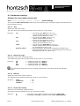
Analog input 4-20 mA
: for connection of sensors in 2-wire system with ≤ 12 V supply;
allocation of unit, initial value and final value adjustable.
Analog input 0-10 V
: for connection of sensors with voltage output; input resistance 5 MOhm.
≤ 12 V power supply for sensors, max. 100 mA; allocation of unit, initial
value and final value adjustable.
3.4
Measuring Uncertainty
Input FA
: +/- 1 Hz
Input VA
: +/- 1 Hz
Input TA
Temperature display
: +/- 1 (0.7 % of meas. value + 0.02 % of full scale)
: +/- 1 Kelvin
Analog input 0-10 V
: +/- 1 (0.3 % of meas. value + 0.02 % of full scale)
Analog input 4-20 mA
: +/- 1 (0.3 % of meas. value + 0.02 % of full scale)
Input Pt100
: +/- 0.2 Kelvin
Analog output 1+2, 0-10 V
: +/- 1 (0.2 % of meas. value + 0.02 % of full scale)
All values are valid for adjusted damping of 30 seconds while measurement. The measuring uncertainties
of the used sensors have to be considered additionally.
4
Initial Operation / Startup
For installation and operation of the system, especially in category 3G, the national regulations currently
in force, the recognised standards of good practice and these Operating Instructions are decisive.
4.1
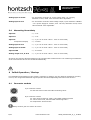
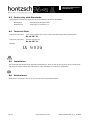
Connector sockets
5-pin connector socket:
for thermal sensors TA10 and TADi measuring tubes
8-pin connector socket:
for vane wheel sensors FA, FAR, FT and FADi measuring tubes
for vortex sensors VA, VAT and VADi measuring tubes
for temperature sensors Pt100
Always connect just one sensor at a time!
8/33
www.hoentzsch.com
U408_flowthermNT_B_e_110809