1
Operating Instructions
flowtherm NT
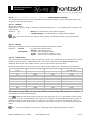
12-pin connector socket:
for analog outputs 2 x 0-10 V
for analog input 4-20 mA
for analog input 0-10 V
USB connector socket type B
data logger readout, hardware configuration
for external power supply via PC or adapter plug
Always make sure that the connector sockets not in use are firmly capped, the sensor plug is
screwed on tightly and the USB connection cover is tightly sealed, otherwise the IP65 protection
cannot be guaranteed
4.2
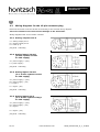
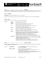
Wiring diagram for the 8-pin connector plug
Electrical connection must be carried out according to the relevant wiring diagram.
Incorrect connection can cause serious damage to the electronics.
Wiring diagram with view of solder contacts:
Pin assignment
pin 1: v/FA+FAR signal 1 F or v/VA signal F
pin 2: ground G
pin 3: PT100
pin 4: PT100
pin 5: PT100
pin 6: PT100
pin 7: v/FAR signal 2 F
pin 8: V+
housing: shield
U408_flowthermNT_B_e_110809
www.hoentzsch.com
4
5
2
1
3
8
6
7
9/33