1
USER'S MANUAL
DP5.0
SWITCHING POWER AMPLIFIERS WITH PFC
Professional Power Amplifier DP5.0
CH1.-dB
CH2.-dB
The information contained in this manual is subject to change without notice.
No part of this manual may be reproduced or transmitted in any form or by any means,
electronic or mechanical, including photocopying and recording of any kind.
HJH Products
Service Information Form
Owner's Name:
Shipping address:
Street:
City:
Zip Code:
Country:
Phone Number:
Email:
MODEL:
NUMBER:
Place of Purchase:
Name of Dealer:
Full Address:
DATE OF PURCHASE:
Fax Number:
SERIAL:
Nature of the problem
(Be sure to describe the conditions that existed when the problem occurred and what
attempts were made to correct it.)
Other equipment in your system
If warranty has expired, payment method:
Cash
Check
card number:
Signature:
Visa
Master
Enclose this form with the defective unit. Do not mail separately.
DP5.0 Switching Power Amplifier
DP5.0 Switching Power Amplifier
LIMITED WARRANTY
NOTES:
THE WARRANTY
For a period of One (1) year from the date of delivery to the original purchaser (as shown on the original invoice or sales
receipt), HJH International Group Limited warrants to the ORIGINAL OWNER of each product (provided it was purchased
at an Authorized HJH Dealer) that it is free of defects in materials and workmanship and that each product will meet or
exceed all factory published specifications for each respective model. HJH agrees to repair or replace (at its discretion) all
defective parts at no charge for labor or materials; subject to following provisions:
WARRANTY VIOLATIONS
HJH shall take no responsibility for repair or replacement as specified under this warranty, if the damaged product has
been subject to misuse, accident, neglect or failure to comply with normal maintenance procedures; or if the serial
number has been defaced, altered or removed. Nor will HJH accept responsibility for, or resulting from, improper
alterations or unauthorized parts or repairs. This warranty does not cover any damage to speakers or any other
consequential damage resulting from breach of any written or implied warranty.
HJH WARRANTY PROVISIONS
HJH will remedy any defect, regardless of the reason for failure (except as excluded ) by repair, or replacement. HJH will
remedy the defect and ship the product within a reasonable time after receipt of the defective product at an HJH
Authorized Service Center.
TO OBTAIN WARRANTYSERVICE
In the event that an HJH product requires service, the Owner must contact HJH or an Authorized HJH Service Center to
receive an R.A.N. ( Return Authorization Number) and instructions on how to return the product to the HJH Authorized
Service Center, or to the factory. HJH (or its Authorized Service Center) will initiate corrective repairs upon receipt of the
returned product. Please save original carton and all the packing materials in case shipping is required. All products being
returned to the factory or service center for repairs must be shipped pre-paid.
If the repairs made by HJH or the HJH Authorized Service Center are not satisfactory, Owner is instructed to give written
notice to HJH. If the defect or malfunction remains after a reasonable amount of attempts by HJH to remedy the defect or
malfunction, the Owner shall then have the option to elect either a refund or replacement of said HJH product free of
charge. The refund shall be an amount equal to but not greater than the actual purchase price, not including any taxes,
interest, insurance, closing costs and other finance charges (minus reasonable depreciation on the product). If a refund is
necessary, the Owner must make the defective or malfunctioning product available to HJH free and clear of all liens or
other restrictions.
MODIFICTTIONS OF EQUIPMENT
HJH reserves the right to modify or change equipment (in whole or part) at any time prior to delivery thereof, in order to
include therein electrical or mechanical improvements deemed appropriate by HJH; but without incurring any liability to
modify or change any equipment previously delivered, or to supply new equipment in accordance with any earlier
specifications.
WEEE Mark
If you want to dispose of this product, do not mix with general
household waste. There are separate collection systems for used
electronic products in accordance with legislation under the WEEE
Directive (Directive 2002/96/EC) and is effective only within the
European Union.
DISCLAIMER OF CONSEQUENTIAL AND INCIDENTAL DAMAGES
YOU,THE OWNER, ARE NOT ENTITLED TO RECOVER FROM HJH ANY INCIDENTAL DAMAGES RESULTING
FROM ANY DEFECT IN THE HJH PRODUCT. THIS INCLUDES ANY DAMAGE TO ANOTHER PRODUCT OR
PRODUCTS RESULTING FROM SUCH ADEFECT.
WARRANTY ALTERATIONS
No person has the authority to enlarge, amend, or modify this Warranty. This Warranty is not extended by the length of
time which the Owner is deprived of the use of product. Repairs and replacement parts provided pursuant to the
Warranty shall carry only the non-expired portion of the Warranty.
THIS STATEMENT OF WARRANTY SUPERSEDES ALL OTHERS CONTAINED IN THIS MANUAL
Page 12
Reference Manual
Reference Manual
Page 1
DP5.0 Switching Power Amplifier
The information furnished in this manual does not include all of the details of design and engineering of this
particular product; not does it cover every possible application or situation concerning its usage, which may
occur during the installation, operation or maintenance of said HJH product.
DP5.0 Switching Power Amplifier
Service
This unit has very sophisticated circuitry and should only be serviced by a fully trained
technician.
This is why each unit bears the following label:
IMPORTANT
THE PRODUCT REQUIRES CLASS 2 OUTPUT WIRING.
CAUTION
TO PREVENT ELECTRIC SHOCK, DO
NOT REMOVE TOP OR BOTTOM
COVERS. NO USER SERVICEABLE
PARTS INSIDE. REFER SERVICING
TO QUALIFIED SERVICE
PERSONNEL. DISCONNECT
POWER CORD BEFORE REMOVING
REAR PANEL COVER TO ACCESS
GAIN SWITCH.
Shock Hazard - Do Not Enter
Choc Hasard - N*entrent
Schocke Hazard - Test Nicht
Betrete
Urto Hazard - Do Non Entrano
To prevent electric shock, do not remove covers. No user serviceable parts inside. Refer
servicing to a qualified technician.
Worldwide Service
Service may be obtained from your local authorized service center. To obtain service, simply
present your sales receipt as proof of purchase along with the defective unit to an authorized
service center. They will handle the necessary paperwork and repair. Remember to transport
your unit in the original factory packaging.
1. When sending a HJH product to the authorized service center for service, be sure to fill out
the service information form that is enclosed at the end of this manual and include it inside
your unit's shipping pack. Do not send the service information form separately.
WARNING
TO REDUCE THE RISK OF ELECTRIC
SHOCK, DO NOT EXPOSE THIS
EQUIPMENT TO RAIN OR MOISTURE!
2. To ensure the safe transportation of your unit to the authorized service center, ship it in an
original factory-packing container.
Magnetic Field
CAUTION: Do not locate sensitive high-gain equipment such as preamplifiers or
tape decks directly above or below this unit. Because this amplifier has a high
power density, it has a strong magnetic field which can induce hum into
unshielded devices that are located nearby. This field is strongest just above and
below the unit. If an equipment rack is used, we recommend locating the
amplifier(s) at the bottom of the rack and the preamplifier or other sensitive
equipment at the top.
3. Do not ship the unit in any kind of rack. Ignoring this warning may result in extensive damage
to the unit and the equipment rack. Accessories are not needed. Do not send the instruction
manual, cables and any other hardware.
The lightning bolt triangle is used alert the user to the risk of electric shock
The exclamation point triangle is used to alert the user to important operating
and/or maintenance instructions.
Printed on recycled paper.
Page 2
Reference Manual
Reference Manual
Page 11
DP5.0 Switching Power Amplifier
SPECIFICATIONS
Introduction
Congratulations on your purchase of a DP5.0 audio power amplifier. We would like to thank
you for your confidence in us and our products.
All the components were specially selected. Although the amplifier was designed to allow
straightforward and uninterrupted operation, improper handling or incorrect installation
could damage the power amplifier.
Your amplifier represents the latest technology in power amplifier design. Please read this
manual carefully as it contains information vital to the safe operation of your amplifier.
DP5.0
MODEL
Max output power
RMS at 1 kHz and 1% THD
8
per channel (Watt)
1800
4
per channel (Watt)
3300
2
per channel (Watt)
5000
8
bridged (Watt)
6600
4
bridged (Watt)
10000-1
(Note-1.Max output @4ohms bridge with burst signal 100ms)
THD at 1 kHz and 1 dB below clipping
0.10%
Slew rate
55V/
Dampping Factor
1000
Sensitivity
26dB/32dB/1.4V
Input connectors
XLR Female
Link connectors
XLR Male/Phonejack
Mode Switch
Stereo/Bridge/Parallel
Outut Conneet
Speakon
Operation voltage, 230V/115V
98-242V
s
Power factor cos( )
Soft Start
Yes
Power mode
PFC Switching power
Dimensions ( W x D x H )
Unit ( mm )
483 x 471 x 89
Packing ( mm )
575 x 568 x 163
13.8
Gross Weight
17.8
Max output power
8
(Watt)
1300
4
(Watt)
2300
2
(Watt)
3200
The DP5.0 amplifier has an automatic power factor correction system for a perfect main
network interface. The amplifier is a resistive load for the main network, minimizing the
reactive power and the harmonic distortion on the current. The system allows performance to be maintained even in circumstances of varying the mains voltage.
Page 10
Unpacking
Check the carton box and its contents immediately to see if there is any sign of damage.
Upon unpacking inspect the amplifier, if you detect any damage inform the forwarding
agentwithout delay and ask for the damage to be documented.
Claims can only be made against the forwarder agent by the consignee.
Be sure to save the carton and all packaging materials for the carrier's inspection.
It's a good idea to save the carton and packing material even if the amplifier has arrived in
good condition. Should you ever need to ship the unit back to service office, or one of its
Service Center. Using only the original factory packaging will be the best way to save the
unit from carrier negligence.
Installation/Mounting
All DXP models amplifiers are 2- rack space units that can mount in a standard 19" rack.
Four front panel mounting holes are provided.
Rear mounting ears give additional support especially important in mobile sound systems.
The unit should not to be installed in a location with:
Too high ambient temperature, dust build-up or excessive humidity;
Fog machines output's oriented to the area of the amplifier;
Exhaust air ventilators and similar units near the area of the amplifier;
With permanent vibrations;
With excessive induction or magnetic fields due to tranformers and transmitters;
Power factor correction
DP5.0 is a amplifier constructor to use power factor correction. This unique feature ensures
that a predominantly resistive load is presented to the mains power supply, minimizing
current distortion and voltage/current displacement This leads to much improved performance of the amplifier at high levels of output and avoids mains-voltage collapses, typical
of standard and switching power supplies. Another great advantage of this technology is
that its performance is, to a large extent, independent of the mains voltage. The rated
output power does not vary with load/line conditions.
Weight ( kg )
Net Weight
DP5.0 Switching Power Amplifier
Reference Manual
The Show Always Goes On
DP5.0 is completely protected against every possible error in operation and is designed to
work under every condition. It gives you maximum power with maximum safety and
increases long-term reliability. Anticipating potential problems at the design stage means
your show always goes on!
Reference Manual
Page 3
DP5.0 Switching Power Amplifier
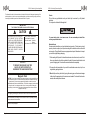
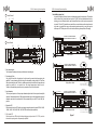
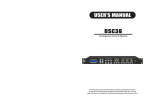
Front Panel
1
7 6 5
4
8
Professional Power Amplifier DP5.0
CH1.-dB
DP5.0 Switching Power Amplifier
Parallel Mode (Input Link)
In parallel mode both channels' inputs are linked and receive the same signal. The parallel
mode is active if the Link switches are in position "PARA". Both level attenuators are active,
allowing you to set different levels for each channel. Note that only the inputs are connected
in parallel. This is NOT a parallel mono mode. Never connect either positive output terminal
to ground or in parallel.You may use the remaining input connectors to carry the signal to
other amps. NOTE:Always turn off the Link switch when using the amplifier for Bi-amping.
CH2.-dB
CHANNEL 2
3
2
3
9
CAUTION: TURN OFF AMPLIFIER
BEFORE CHANGING THIS SWITCH
PARALLEL
STEREO
BRIDGE
15
17
10
LOUDSPEAKERS
Rear Panel
12 13
CHANNEL 1
Stereo Mode
CH 1
CH 2
MIXER
16
15
2-
12 13 14
CAUTION: TURN OFF AMPLIFIER
BEFORE CHANGING THIS SWITCH
PARALLEL
STEREO
BRIDGE
LOUDSPEAKERS
1. Rack mounting ears
Two front panel mounting holes are provided on each mounting ear.
2. Fan intake grill filter
One grill with foam filter is located on the front panel to prevent dust from entering the
amplifier. For easy cleaning of the filter the grill is removable by simply pulling it off. The foam
filter should always be used. The fan's variable speed control ensure low noise operation and
adapt the quantity of air required from the actual temperature inside the unit.
Thanks to this advanced system low noise is guarantee. Do not block this intake!
4. Signal bar LED
Each channel has a bar LED, as the input signal strength increase, the green SIGNAL -30dB,
-24dB, -18dB, -12dB, -9dB, -6dB, -3dB, 0dB LED indicators light respectively.
CHANNEL 2
CHANNEL 1
Reference Manual
MIXER
PARALLEL
STEREO
BRIDGE
Parallel Mono Mode
Only use the CH 1 Input
CH 2 is not used in the mode
MIXER
5. Clip/Limiter LED
Each channel has a LED that light at the real clipping point (more than 0.5% T.H.D.) and also
indicates the input signed is compressed by amplifiers.
Page 4
CAUTION: TURN OFF AMPLIFIER
BEFORE CHANGING THIS SWITCH
Only use the CH 1 Input
CH 2 is not used in the mode
LOUDSPEAKERS
3. Input attenuator
Two front panel precision 41 steps input attenuator adjust level for their respective amplifier
channels. Minimum attenuation (-0dB) equals maximum output. In the bridge mode both level
attenuator must be at the same position. We recommend that you set CH1 to the -0dB (full)
position.
Bridge Mono Mode
Figure 1
Reference Manual
Page 9
DP5.0 Switching Power Amplifier
Cooling Requirements
Amplifier use a forced air cooling system to maintain a low, even operating temperature.
Drawn by a infinitely variable speed fans mounted inside the unit, air enters through the
front
grills with dust filter, and courses through the cooling fins of the heatsinks, which dissipates
power transistor heat, before exiting through the rear panel ports. Make sure that there is
enough space around the front of the amplifier to allow air to enter, and around the units to
allow the heated air to exit. If the amp is rack-mounted, do not use doors or covers on the
front and rear of the rack; the air must flow through the amplifier without resistance.
Note: whatever type of rack you are using, make sure that the heated air can escape freely,
and that there is not resistance to the intake of cool air through the front grill.
Configuration
Use the configuration switch and the internal jumpers to configurate the amplifier to meet
your requirements. The setup must be done with the unit switched off. With the switches and
jumpers is possible to configurate the amplifier for the following functions:
Stereo Mode (standard)
In stereo mode, the channels operate independently, with their input attenuators controlling
the respective channel's level. Recommended minimum nominal load impedance for stereo
operation is 4 or 2 Ohms per channel (as indicated on the specifications). Loudspeakers are
connected to the speakon outputs CH 1 or CH 2. For reference see Figure 1
Bridged Mono Mode
In Bridged Mono mode, both amplifier channels work with the same input signal, but with
inverse phases. The result is a doubling of the output voltage and thus double the power on
the double impedance. If the amplifier is to be operated in Bridged Mono mode, ONLY one
input may be used CH1. We recommend that you set them to the -0dB (full) position.
Loudspeakers are connected to the speakon output CH 1. For reference see Figure 1.
DP5.0 Switching Power Amplifier
6. Protect LED
Each channel has a Protect LED that will light when the load connected is lower than 1 Ohm
or amplifier broken. If the amplifier is going to operate above its maximum operating
temperature (900C).The indicator first comes on as a warning to either turn down the input
level or check the cooling arrangements. Beyond the maximum temperature the amplifier
will mute the input signal. Once the cooling fans have brought the output heat sinks back to
normal operating temperature the input signal is un-muted.
7. Bridge LED
The Yellow active LED illuminates to indicate that the amplifier is work at bridge mode.
8. Power LED
The green active LED illuminates to indicate that the amplifier is turned on, and works
correctly.
9. AC power switch
Use this to switch on the amplifier. A soft-start system limits the start-up surges.
10. Fan exhaust ports
Heated air exits the amplifier through the exhaust ports, located on the rear of the amplifier
chassis. Be sure not to block this ports, especially when rack mounting the amplifier.
11. Input connectors
XLR female is provided on each channel for balanced or unbalanced input. Unfortunate
wiring, in the proximity of dimmers or other generalised phase controls, motors, transformer, etc. can cause interference into your system. You will hear loud humming or a
bumping noise in the loudspeakers. Balanced wiring suppresses these noises quite
significantly.
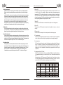
12. Impedance matching(OVP switch)
The OVP switches are located on the rear panel. The OVP (Minimum Load Select)switches
Offer impedance matching, so you can drive the DP5.0 into 2 ohms without increased heat
loss.
As stated earlier, the DP5.0 can produce 2300 watts into both, 2 and 4 ohms. Use lower
OVP settings when connecting to lower impedance loads as shown in table 1. As can be
seen in table 1, the DP5.0 can produce output power in excess of 2000 watts.
Page 8
Reference Manual
LOAD
16 ohms
8 ohms
4 ohms
2 ohms
CONFIGURATION
Stereo (2 channel)
Stereo (2 channel)
Stereo (2 channel)
Stereo (2 channel)
-5 dB
220 W
430 W
830 W
1660 W
OVP SWITCH SETTING
-4 dB
-2 dB
0 dB
260 W
410 W
650 W
520 W
820 W
1300 W
1000 W
1600 W
2300 W
2000 W
2400 W [2] 2900 W [2]
3050 W [1] 3200 W [1]
16 ohms
8 ohms
4 ohms
Bridge mono
Bridge mono
Bridge mono
860 W
1660 W
3320 W
1040 W
2000 W
4000 W
Reference Manual
1640 W
2400 W
4800 W
2600 W
4600 W
5800 W [1]
Page 5
DP5.0 Switching Power Amplifier
13. Input Sensitivity/Gain
The standard settings are:1.4V,32dB,26dB,selection is independent for each channel. Use
this function to match the amplifier's sensitivity/gain with the other connected equipment.
As option, is possible adjust the unit for any sensitivity/gain.Note that every increase of the
gain will decrease the S/N ratio.
14. Mode operation switches
Setup these switches for the desired operation mode. For reference see Figure 1.
DP5.0 Switching Power Amplifier
Operation
Operating voltage
WARNING!
A label just below the mains cable on the rear of the amplifier indicates the AC mains voltage for which the amplifier is wired. Connect the power cable only to the AC source referred
to on the label. The warranty will not cover damage caused by connecting to the wrong type
of AC mains.
15. Speakon output connectors
The unit has four Speakon connectors as outputs: CH 1 and CH 2. Every one permit the connection of both channels for stereo operation or parallel mode. For bridge operation the
CH1 connector should be used. For reference see Figure 1.
DP5.0 switch mode amplifiers use primary switching. The mains power is being rectified
directly in front of the transformer, meaning that the power supply is insensitive to the mains
frequency .
If the power plug is not appropriate for your country, it can be cut off and wired to a suitable
connector in the following way:
16. A.C. Power cable
The unit have one A.C. power cable. Before connection, be sure that the cable is not frayed
or broken. The connection must be made only in a plug with the electrical ground wire system.
BLACK or BROWN
WHITE or BLUE
GREEN or GREEN / YELLOW
17. S.N. label
Every unit has a label indicating: the model, and the barcode serial number.
LIVE
NEUTRAL
EARTH
Once the AC connector is connected to a suitable AC supply, the amplifier can be started
with the power switch. When you power up the amplifier it takes a couple of seconds to
check its circuits(this is known as the soft start or slow start sequence), the fans then blow
at high speed before going into idle, and the two bottom green LEDs come on to show the
output circuits are receiving the correct rail voltage.
Grounding
There is no ground lift switch or terminal on this amplifier. The signal ground is always
floating via a resistor to chassis, and the grounding system is automatic. If a potential above
0.6V is presents in between signal ground and chassis ground, a short circuit is introduced
between the two, thereby enabling electrical protection. If a unit in the system is faulty, its
mains fuse will blow due to this automatic ground system. If however you wish to tie the signal ground to chassis, connect the XLR-connector`s shell lug to pin 1. In the interest of
safety never disconnect the earth pin on the AC power cord.
For all units that are FCC approved (radio interference), there is an AC mains filter. This filter needs the chassis ground for reference, otherwise a current loop is formed via the signal
ground. Use the balanced input to avoid hum and interference.
Connecting Power and Circuit size requirements
Amplifier's power requirement are rated at idle, at 1/8 and 1/3 power ("severe" music condition).The maximum power current draw rating is limited only by the internal fuses. Consult
the specification at the end of this manual for the power each amplifier will demand. Mains
voltage must also be correct and the same as that printed on the rear of the amplifier.
Damage caused by connecting the amplifier to improper AC voltage is not covered by any
warranty.
Note: always switch off and disconnect the amplifier from mains voltage before making
audio connections, and as an extra precaution, have the attenuators turned down during
power-up.
Page 6
Reference Manual
Reference Manual
Page 7