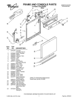
1
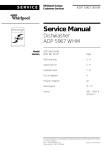
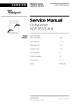
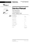
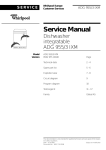
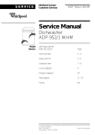
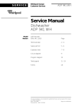
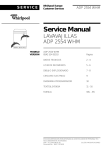
SERVICE
Whirlpool Europe
Customer Services
ADP 5656/1 WHM
Service Manual
Dishwasher
ADP 5656/1 WHM
Model
Version
ADP 5656/1 WHM
8542 656 10750
Page
Technical data
2-4
Spare part list
5-6
Exploded view
7-8
Circuit diagram
9
Program diagram
10
Text/Legend
11 - 17
Family
VBL - MID 6
This documentation is only intended for qualified technicians who are aware of the respective safety regulations.
Date: 04.06.2002
Subject to modification
Document-No.: 4812 718 17975
04.06.2002 / Page 2
Doc. No: 4812 718 17975
ADP 5656/1 WHM
8542 656 10750
Whirlpool Europe
Customer Service
SERVICE
Technical data
Dimension of Free standing appliances with
rounded outer door
Height
Width
Depth
Weight
85.0
59.7
61.0
56
cm
cm
cm
kg
Electronic boards
Service boards
see spare part list
Serial boards
see on the boards itself
DUB
4619 724 06781
Programing of version and programmed control
board, see „Service“ and „Data set“ on rating
plate of inner door:
CB programmed
442311
Data set
442301
Basic control board, not programmed see on the
board itself
4619 724 17411
Program information
Start indicator
Pre wash
Main wash
Drying
End
All programs will be locked after start. Changing
the program or finishing the program will be
possible only after pressing the start button for
longer then 1.5 sec. (Break by customer)
A switching off the appliance or unplug the
appliance for a while, this will frozen the program
step and later on, the program continuos on the
same position.
Exception: Switching off the appliance or unplug
the appliance during the drying phase, this will lead
directly to the end of the program.
Succession of programs
Programs
Succession
see program diagram
A1a - A3a - A5b - A6a - A7a
Datas Energy Label
Reference program
Energy Performance
Cleaning Performance
Drying Performance
Alarms
Refill rinse aid
Refill salt
Options
Zone washing
Delay function
A5b
B
A
B
Water Volume at alternating spray system
Volume at alternating spray system (same level
when selected zone washing as in the normal
programs)
Water
Regeneration
Back rinse 3x
Prewash
Main wash
Intermediate rinse 1
Intermediate rinse 2
Clear rinse
Safety/ overflow
Volume
0.3 l
1.0 l
3.9 l
3.2 l
3.2 l
3.2 l
3.2 l
8.5 l
Level
15 mm
60 mm
120 mm
118 mm
118 mm
118 mm
118 mm
141 mm
Measuring the level
Remove the coarse sieve, put in a measuring
meter into the sump, measure the hight of the
water level.
Detergent max.
Pre-wash
Main-wash
Rinse aid
6 Dosage steps
10
40
135
1-6
cm3
cm3
cm3
ml
2
900
300
kg
cm3
cm3
Water softener
Saltcontainer
Resin container
Regeneration dosage
SERVICE
Whirlpool Europe
Customer Service
ADP 5656/1 WHM
8542 656 10750
04.06.2002 / Page 3
Doc. No: 4812 718 17975
Technical data
Water pressure
Inlet pressure
Spray pump pressure
Electrical base data
0.3 - 10
0.3
bar
bar
2800
3000
30 - 40
30 - 40
RPM
RPM
RPM
RPM
Voltage
Frequency
Total power
Fuse
220/ 230
50
2.0 - 2.2
10
V
Hz
kW
A
Rotations
Spray pump motor
Drain pump motor
Spray arm lower
Spray arm upper
Spray arms, turning rhythm at alternating spray
system
Turning starts every time with the upper spray arm
Pre wash Lower arm ~3min, Upper arm ~1min
Main wash Lower arm ~3min, Upper arm ~5min
Intermediate rinse
Lower arm ~2min, Upper arm ~2min
Final rinse Lower arm ~2min, Upper arm ~2min
Service Test program
Lower arm ~30sec, Upper arm ~30sec
Remark: When switching of the main switch or
interrupt the mains during the Test Program runs,
then the alternating of the spray arms change in
the test program to the rhythm of main wash 5/3
min.
Important: To leaf the Test program is possible by
made a break by customer (pushing the start
button for 1.5 sec.)
After finishing the test program (End LED shines
and/or Start LED goes of) must the appliance be
switched off.
If this will not be done, then the next normal wash
will be made with the frequency of the Service
Test Program ~30/30sec.
Flow rates/ Inlet volume
Flow meter (at 0.3 bar
= quantity 1.1 l/min)
Spray pump
Drain pump
Pump height max.
Inlet valve
Spray arm lower
Sprayarm upper
Shower top
208
45 - 65
16
1.1
4
~ 33
~ 27
~8
lmp/l
l/min
l/min
m
l/min
l/min
l/min
l/min
Motor
Spray pump motor alternating spray system
Voltage
Power consumption
HI
HA
Capacitor
220/ 240
125
79
60
4
V
W
Ω
Ω
µF
Drain pump motor
Voltage
Power consumption
Resistance
220/ 240 V
30
W
146
Ω
Heating
1 Element system
Voltage
Power consumption
Resistance
Heating speed
Temperature on surface
Safety thermostat
self reset
(Temperature of water)
Fuse
220/ 230
1.87/ 2.04
24.5
~ 2.0
~ 115
V
kW
Ω
˚C/min
˚C
~ 85
206
˚C
˚C
Potentiometer
Points of meassurement:
Position 0
Position 1
Position 2
Position 3
Position 4
Position 5
Position 6
1(black) to 2 (middle)
0.0
kΩ
0.5
kΩ
1.0
kΩ
1.4
kΩ
1.8
kΩ
2.3
kΩ
2.6
kΩ
04.06.2002 / Page 4
Doc. No: 4812 718 17975
ADP 5656/1 WHM
8542 656 10750
Whirlpool Europe
Customer Service
SERVICE
Technical data
Single electric inlet valve
Voltage
Frequency
Resistance
Regeneration
220/ 240 V
50/ 60
Hz
3.76
kΩ
Regenerating valve
Voltage
Frequency
Resistance
220/ 240 V
50/ 60
Hz
3.13
kΩ
Volume
Position 0
after wash cycles
water hardness
Position 1
after wash cycles
water hardness
Motor Diverter Valve
Voltage
Frequency
Resistance
Signal (2x within ~13 sec.)
220 - 240
50/ 60
6.5
5.0
V
Hz
kΩ
V
Position 3
after wash cycles
water hardness
Coil of dispenser
Voltage
Frequency
Resistance
Position 2
after wash cycles
water hardness
220/ 240 V
50/ 60
Hz
1.3
kΩ
Position 4
after wash cycles
water hardness
Reed contacts
Position 5
after wash cycles
water hardness
flow meter
salt control
rinse aid control
NTC
20 ˚C
25 ˚C
30 ˚C
40 ˚C
50 ˚C
60 ˚C
70 ˚C
80 ˚C
85 ˚C
58.1
47.1
38.2
25.4
17.2
11.8
8.3
6
4
kΩ
kΩ
kΩ
kΩ
kΩ
kΩ
kΩ
kΩ
kΩ
Position 6
after wash cycles
water hardness
300
cm3
12
0-5
0 - 0.9
0-9
˚dh
mmol/l
˚Fh
10
6 - 10
1 - 1.8
10 - 18
˚dh
mmol/l
˚Fh
7
11 - 15
1.9 - 2.7
19 - 27
˚dh
mmol/l
˚Fh
5
16 - 21
2.8 - 3.7
28.37
˚dh
mmol/l
˚Fh
3
22 - 28
3.8 - 5.0
38 - 50
˚dh
mmol/l
˚Fh
2
29 - 35
5.1 - 6.3
51 - 63
˚dh
mmol/l
˚Fh
1
36 - 60
˚dh
6.4 - 10.7 mmol/l
64 - 107 ˚Fh
Salt consumption
for regeneration
77
Number of cycles
with 2 kg salt
26
g
Accesory
If you need spare parts apart from the spare
part list have a look in the
Service Bulletin 4812 718 40084.
SERVICE
Whirlpool Europe
Customer Service
ADP5656/1WHM
8542 656 10750
04.06.2002 / Page 5
Doc. No: 4812 718 17975
Spare part list
Model
Service No.
Version
ADP 5656/1 WHM
854265610750
854265610750
Pos. No. 12NC Code
Description
Pos. No. 12NC Code
Description
003 0
004 0
004 1
011 0
022 0
4812 440 19594
4812 440 18952
4812 401 18402
4812 505 18357
4812 440 18951
Traverse
Drip tray assy
Holder
Foot short
Side panel left
405 1
420 0
421 0
430 0
430 1
4819 515 28158
4812 121 18132
4812 121 18158
4812 360 18508
4812 466 68689
Gasket
Capacitor
Interf.filter
Pump,draining cpl.
Gasket
022 1
024 0
030 0
034 0
034 1
4812 440 18949
4812 440 10417
4812 440 19755
4812 404 78237
4812 404 78242
Side panel right
Panel, rear
Table top WH
Spacer
Fastener table top
450 0
480 0
480 1
480 3
490 0
4812 259 28684
4812 321 28405
4812 321 28371
4812 401 18418
4819 321 18136
Heating element
Cable harness set
Cable
Protector f.wiring
Cable,mains 2m SA
040 1
040 2
040 3
044 0
047 0
4812 417 18774
4812 417 18773
4812 417 18923
4812 492 38358
4812 404 48746
Hinge left
Hinge right
Protector f.door (set)
Spring f.door
Brake f.door
490 1
521 0
531 0
531 1
575 0
4812 321 28367
4812 214 78632
4812 273 18055
4812 273 18056
4812 281 28361
Strain relief
Control board (CB)
Switch waterhardness
Wheel,fingertip
Regen.valve
047 1
047 2
053 0
053 4
103 0
4812 401 18397
4812 404 68023
4812 440 88887
4812 440 88928
4812 440 19756
Band,brake
Hook
Plinth WH
Plinth rounded WH
Door outer WH
583 0
616 0
616 1
620 0
623 0
4812 271 28407
4812 281 18047
4812 271 58161
4812 218 38101
4812 271 38356
Switch diaphragm
Contact,reed salt
Contact,reed rinsing agent
User board (DUB)
Microswitch
103 2
120 0
120 1
130 0
131 0
4812 440 19778
4812 440 19456
4812 440 18969
4812 417 58361
4812 401 18416
Corner piece set
Door,inner
Batten
Tilt lock cpl. wh
Hook lock
633 0
680 0
680 1
681 1
681 2
4812 271 38355
4812 418 68155
4812 466 68495
4812 466 68497
4812 440 18975
Microswitch door
Combidosage
Gasket
Gasket
Flap
191 0
192 0
241 0
241 1
241 3
4812 466 68564
4812 466 68467
4812 458 19027
4812 458 18324
4812 528 88068
Gasket door
Gasket, door lower
Basket upper straight
Holder cups right wh
Wheel,basket upper (set)
682 0
691 0
700 0
700 0
700 1
4812 466 68496
4812 282 68012
4812 530 28804
4812 530 28848
4812 480 48095
Gasket
Feeler NTC
Hose, inlet aqua stop 4,2m
Hose, inlet aqua stop 2m
Sieve
241 4
241 5
241 7
241 8
242 0
4812 458 18984
4812 535 78043
4812 404 48683
4812 466 68553
4812 310 28136
Holder dishes wh
Bearing
Hoop
Spacer cap set
Basket lower KIT
700 2
701 1
710 0
710 2
710 3
4812 466 68628
4812 310 18153
4812 418 68128
4819 310 38536
4819 466 69562
Gasket
Yoke clamp set
Monoblock
Threaded ring
Gasket set
242 1
242 4
242 6
242 7
243 5
4812 528 88069
4812 466 48091
4812 458 18977
4812 458 18978
4819 310 39859
Wheel,basket lower wh
Fixation gr
Support plate left
Support plate right
Cutlery basket KIT
714 0
716 0
716 1
716 2
717 0
4812 462 78993
4812 418 68147
4812 466 68475
4812 462 78994
4812 281 28418
Threaded cap
Reg.dosage
Gasket
Cover
Valve motordiverter
243 6
261 0
261 1
261 2
263 0
4812 458 18996
4819 462 38271
4812 462 79768
4812 462 78995
4819 520 18013
Grille wh
Rail telescope, inner
Cap rail
Cap rail ahead
Ball cage cpl.
717 2
717 3
721 1
722 0
722 2
4812 528 98011
4812 530 29121
4812 360 68347
4812 360 68348
4812 360 68349
Valve disk diverter
Gasket diverter valve
Spray arm lower. cpl.
Spray arm upper wh
Spray arm 2nd level cpl. wh
263 1
265 0
265 2
303 1
322 0
4812 520 48001
4812 404 48637
4812 404 48638
4812 460 38092
4812 453 71279
Ball Niro 8 D
Basket adjustm. cpl.
Grip basket adjustment
Plate,handle WH
Insert panel
723 0
726 1
726 2
743 0
743 1
4812 360 68351
4812 530 29118
4812 505 18208
4812 511 48171
4812 530 28102
Douche ceiling
Tube assembly cpl.
Nut
Capacitor
Hose, inlet
331 0
332 0
332 1
400 0
405 0
4812 413 59028
4812 410 28669
4812 410 28735
4812 361 58336
4812 360 18509
Knob program cpl. WH
Button WH
Button WH
Motor +SP,50Hz,alt.LP-PNT1
Spray pump wo.Mot.alt.LP-50Hz
743 3
743 4
743 7
751 0
755 0
4812 505 18364
4812 530 28807
4812 466 68514
4812 418 18338
4812 530 29119
Nut
Hose 9x1,5x270+10
Gasket
Water collector
Bend
04.06.2002 / Page 6
Doc. No: 4812 718 17975
ADP5656/1WHM
8542 656 10750
Spare part list
Model
Service No.
Version
ADP 5656/1 WHM
854265610750
854265610750
Pos. No. 12NC Code
Description
755 2
756 0
761 0
761 2
761 3
4812 530 48148
4812 360 58099
4812 480 58122
4812 418 18337
4812 418 18341
Tray,leak
Floater
Sieve fine
Cover sieve
Cover
761 4
763 0
781 0
781 3
783 6
4812 530 58141
4812 480 58123
4812 530 29113
4812 281 28417
4812 530 28796
O-Ring
Sieve coarse
Hose,draining
Flap non-return
Hose 10x3x180+10
791 0
791 2
791 4
791 5
901 0
4812 532 68099
4812 530 58093
4812 466 68503
4812 466 68504
4822 401 10258
Gasket
Gasket
Gasket
Gasket
Clamp,hose 10-18 mm
901 1
901 2
901 5
904 2
910 1
4812 401 18424
4812 401 18157
4812 401 48573
4812 462 79635
4812 502 38152
Strap 050,0
Strap 32-50/9 C61
Strap 028,6
Cover WH 3,5x5
Screw 4,8x19
910 2
910 3
910 4
910 5
910 7
4812 502 18363
4812 502 18389
4812 502 18385
4812 502 18393
4812 502 18397
Screw 4,0x12-H
Screw 5x20 T20
Screw M3,5x8-T15M
Screw 3,5x9-1 Tx15
Screw INOX A2 M 5X12
910 8
910 9
964 0
964 1
993 0
4812 502 18527
4812 502 18446
4812 466 68536
4812 466 68469
4819 530 29028
Screw 4x15 T20
Screw 3,5x16
Gasket housing ri/le
Gasket housing upper
Bow
993 5
4822 532 80216
Funnel salt
Whirlpool Europe
Customer Service
SERVICE
SERVICE
Exploded view
Whirlpool Europe
Customer Service
ADP 5656/1 WHM
8542 656 10750
04.06.2002 / Page 7
Doc. No: 4812 718 17975
04.06.2002 / Page 8
Doc. No: 4812 718 17975
Exploded view
ADP 5656/1 WHM
8542 656 10750
Whirlpool Europe
Customer Service
SERVICE
black
blue
grey
white
00
66
88
99
Whirlpool Europe
Customer Service
ADP 5656/1 WHM
8542 656 10750
UB
VM
WV1
WV2
WI
ZW
Automatic salt adaption/
Water hardness sensor
Capacitor
Control board
Control unit LCD
Display board
Display- and User board
Timerswitch Delay
Drain pump motor
Cleaning agent dosage
Turbidity sensor
Final rinse dosage
Door switch
Diverter ventil high
Diverter ventil low
Flow meter
Heating
Interference filter
Water leakage switch
Line
Main switch
Thermostat temp. sensor
Neutral
Water indicator, optical
Plug to program
Water hardness switch
Heating relay
Reed relay salt
Reed relay rinsaid
Sprayarm blocked
Sprayarm motor
Safety thermostat
Fuse
Power supply terminal
Winding protective
contact
User board
Fan ventilator
Water inlet valve
Water regenerating valve
Water indicator
Zone washing
ASA/
WHS
C1
CB
CULCD
DB
DUB
DLB
DPM
DD
DON
DR
DS
DVH
DVL
FM
HEWI
IF
LS6
L
MS
NTC
N
OWI
PRG
RV
RE2
RR SA
RR RA
SAB
SPM
THS1
THS 2
TBL
TL
SERVICE
04.06.2002 / Page 9
Doc. No: 4812 718 17975
Circuit diagram
04.06.2002 / Page 10
Doc. No: 4812 718 17975
Program diagram
ADP 5656/1 WHM
8542 656 10750
Whirlpool Europe
Customer Service
SERVICE
SERVICE
Text/Legend
Whirlpool Europe
Customer Service
ADP 5656/1 WHM
8542 656 10750
04.06.2002 / Page 11
Doc. No: 4812 718 17975
04.06.2002 / Page 12
Doc. No: 4812 718 17975
Text/Legend
ADP 5656/1 WHM
8542 656 10750
Whirlpool Europe
Customer Service
SERVICE
SERVICE
Text/Legend
Whirlpool Europe
Customer Service
ADP 5656/1 WHM
8542 656 10750
04.06.2002 / Page 13
Doc. No: 4812 718 17975
04.06.2002 / Page 14
Doc. No: 4812 718 17975
Text/Legend
ADP 5656/1 WHM
8542 656 10750
Whirlpool Europe
Customer Service
SERVICE
SERVICE
Text/Legend
Whirlpool Europe
Customer Service
ADP 5656/1 WHM
8542 656 10750
04.06.2002 / Page 15
Doc. No: 4812 718 17975
04.06.2002 / Page 16
Doc. No: 4812 718 17975
Text/Legend
ADP 5656/1 WHM
8542 656 10750
Whirlpool Europe
Customer Service
SERVICE
SERVICE
Text/Legend
Whirlpool Europe
Customer Service
ADP 5656/1 WHM
8542 656 10750
04.06.2002 / Page 17
Doc. No: 4812 718 17975