1
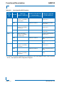
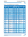
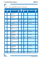
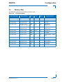
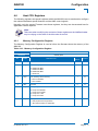
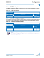
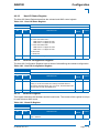
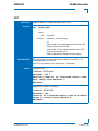
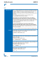
AM4100
4.6.18
Configuration
MMC Configuration Register
The MMC Configuration Register holds a series of bits defining the host serial port routing and
the MMC serial port configuration.
Table 4-27: MMC Configuration Register
REGISTER NAME
MMC CONFIGURATION REGISTER
ADDRESS
0xEC00_029C
BIT
NAME
7
MPGC
RESET
VALUE
ACCESS
0
R/W
0
R/W
Reserved
00
R
MMC serial port configuration for debugging purposes:
1
R
0
R/W
0
R/W
0
R/W
DESCRIPTION
MMC program request:
6
MPGU
MMC enforce User Program Mode request:
0 = No action
1 = Set MMC in User Program Mode (this bit is ignored if MMC is in
local programming mode)
5-4
Res.
3
MCOMT
0 = MMC serial port is connected to the serial front panel RJ45 connector (only for debugging purposes)
1 = MMC serial port is isolated
2
MSCI
MMC serial port configuration for Firmware update:
0 = Host SER1 port is disable
1 = Host SER1 port is connected to MMC serial port (this bit is
ignored if the MCOMT signal is 0)
1
MRST
MMC reset function:
0 = MMC controller is running
1 = MMC controller is in reset state
0
MPGM
MMC program mode; select the Firmware update mode:
0 = Normal operating mode
1 = Set MMC in firmware update mode
4.6.19
IPMI Keyboard Controller Style Interface
The host processor communicates with the MMC using two Keyboard Controller Style (KCS)
interfaces, which are defined in the IPMI specification. One interface is for the System Management Software (SMS) used within an operating system, and one for the System Management
Mode (SMM) used only by the NetBootLoader.
The KCS interface for the system management software is on the I/O location 0xEC00_0CA2
and 0xEC00_0CA3, and configured as regular ISA interrupt.
The KCS interface for the system management mode is on the I/O location 0xEC00_0CA0 and
0xEC00_0CA4, and configured as SMI interrupt.
ID 36126, Rev. 2.0
Page 4 - 23
PRELIMINARY
0 = No action
1 = Request MMC to program internal Flash from external Flash