1
MACH 3xx/4xx Design Considerations
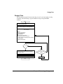
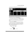
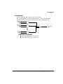
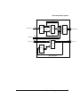
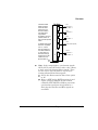
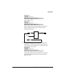
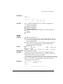
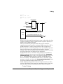
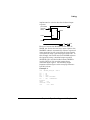
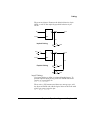
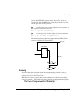
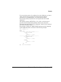
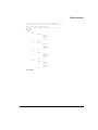
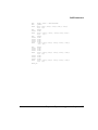
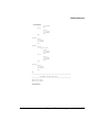
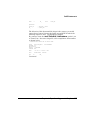
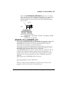
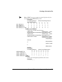
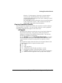
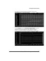
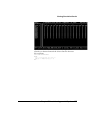
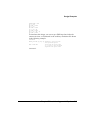
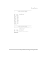
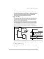
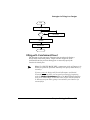
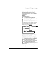
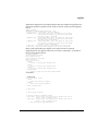
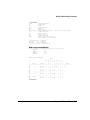
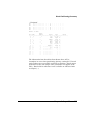
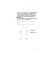
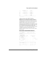
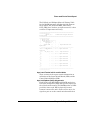
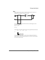
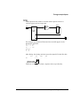
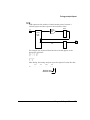
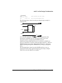
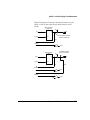
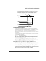
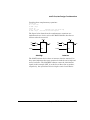
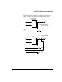
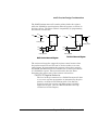
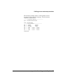
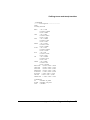
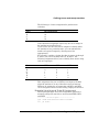
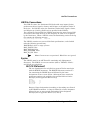
The following figure shows how the same complementary equations
are implemented on a MACH 3xx/4xx device:
SET_A
SET
IN1
IN2
Q
T
CLK
CLOCK
O1
IN1
IN2
Q
T
O2
CLK
CLOCK
RESET
SET_A
Active High
Active Low (Equivalent)
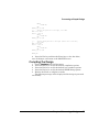
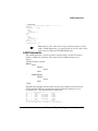
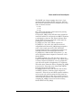
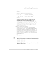
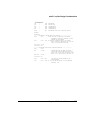
These equations, as implemented on the MACH 3xx/4xx device, can
be expressed as follows:
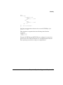
;active high
O1.T = IN1 * IN2
O1.SETF = SET_A
;active low
O2.T = IN1 * IN2
O2.RSTF = SET_A
;same logic as active high
;but different initialization equation
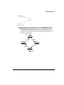
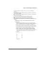
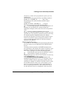
The rules for handling T-type flip-flops can be summarized as
follows:
For T-type flip-flops that feed active-low I/O pins, Set and Reset
are always swapped.
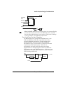
For active-low T-type flip-flops implemented on buried nodes,
references to the buried node are always inverted (regardless of the
22V10/MACH1xx/2xx S/R Compatibility option setting).
Example
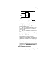
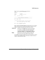
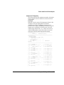
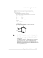
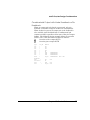
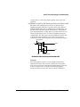
Feedback from the active-low T-type signal TSIG (implemented on a
buried node) is referenced as TSIG on the right side of an equation
for the signal OUT2. In the JEDEC file, the reference to TSIG
appears as /TSIG.
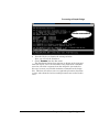
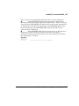
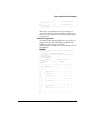
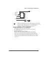
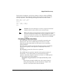
Note: After disassembling a JEDEC file, references to TSIG will
appear as /TSIG.
Latches
Chapter 10: Device Reference
398