1
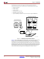
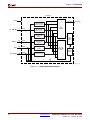
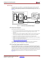
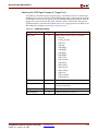
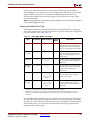
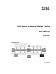
R
Chapter 1: Introduction
The ChipScope Pro Analyzer tool supports the following download cables for
communication between the PC and the devices in the JTAG Boundary Scan chain:
•
Platform Cable USB
•
Parallel Cable IV
•
Parallel Cable III
•
MultiPRO (JTAG mode only)
•
MultiLINX™ (JTAG mode only)
•
Agilent E5904B Option 500, FPGA Trace Port Analyzer (Agilent E5904B TPA)
Target Device Under Test
User
Function
User
Function
Host Computer with
ChipScope Pro Software
ILA Pro
ILA Pro
ChipScope
Pro
User
Function
ICON Pro
Parallel
Cable
ILA Pro
JTAG
Connections
Board-Under-Test
cs_pro_sys_blk_diag
Figure 1-1: ChipScope Pro System Block Diagram
Figure 1-1 shows a block diagram of a ChipScope Pro system. Users can place the ICON,
ILA, ILA/ATC, IBA/OPB, IBA/PLB, VIO, and ATC2 cores (collectively called the
ChipScope Pro cores) into their design by generating the cores with the ChipScope Pro
Core Generator and instantiating them into the HDL source code. You can also insert the
ICON, ILA, ILA/ATC, and ATC2 cores directly into the synthesized design netlist using
the ChipScope Pro Core Inserter tool. The design is then placed and routed using the Xilinx
ISE 7.1i implementation tools. Next, the user downloads the bitstream into the device
under test and analyzes the design with the ChipScope Pro Analyzer software.
1-2
www.xilinx.com
ChipScope Pro Software and Cores User Guide
UG029 (v7.1) February 16, 2005