1
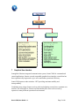
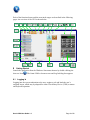
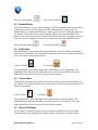
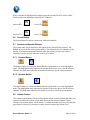
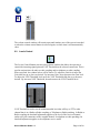
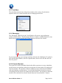
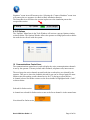
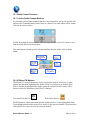
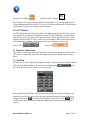
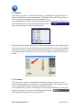
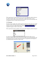
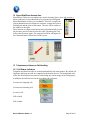
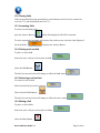
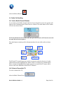
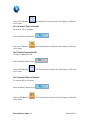
Omni-COM USER GUIDE Omni-COM User Guide 1.3 Page 1 of 28 This system and documentation contain valuable trade secrets and proprietary information belonging to Omniglobe Solutions Ltd. and/or its suppliers. None of the foregoing material may be copied, duplicated or disclosed without the express written permission of Omniglobe Solutions Ltd. Reverse engineering, decompiling and disassembling are explicitly prohibited. Omniglobe Solutions Ltd. EXPRESSLY DISCLAIM ANY AND ALL WARRANTIES CONCERNING THIS SOFTWARE AND DOCUMENTATION, INCLUDING ANY WARRANTIES OF MERCHANTABILITY AND/OR FITNESS FOR ANY PARTICULAR PURPOSE, AND WARRANTIES OF NON-INFRINGEMENT OF INTELLECTUAL PROPERTY RIGHTS OF A THIRD PARTY, PERFORMANCE, AND ANY WARRANTY THAT MIGHT OTHERWISE ARISE FROM COURSE OF DEALING OR USAGE OF TRADE. NO WARRANTY IS EITHER EXPRESS OR IMPLIED WITH RESPECT TO THE USE OF THE SOFTWARE OR DOCUMENTATION. Under no circumstances shall Omniglobe Solutions Ltd. and/or its suppliers be liable for incidental, special, indirect, direct or consequential damages or loss of profits, interruption of business, or related expenses which may arise from use of software or documentation, including but not limited to those resulting from defects in software and/or documentation, or loss or inaccuracy of data of any kind. The specifications and information in this manual are subject to change without notice. Copyright (c) Omniglobe Solutions Ltd. [2011] All rights reserved http://www.omniglobesolutions.ca / Omni-COM User Guide 1.3 Page 2 of 28 Table of Contents 1 2 3 4 5 6 7 8 About This Document..............................................................................................5 Conventions.............................................................................................................5 References ...............................................................................................................5 Omni-COM Introduction .........................................................................................6 Key Attributes .........................................................................................................6 System Functional Overview ...................................................................................6 Graphical User Interface ..........................................................................................7 Getting Started.........................................................................................................9 8.1 Logging In .......................................................................................................9 8.2 To Exit...........................................................................................................10 9 Action Tool Bar Area ............................................................................................ 10 9.1 Answer Button............................................................................................... 10 9.2 Release Button............................................................................................... 11 9.3 Hold Button ...................................................................................................11 9.4 Channel Mute ................................................................................................ 11 9.5 RX and TX Buttons ....................................................................................... 11 9.6 Secure Button ................................................................................................ 12 9.7 Headset and Speaker Buttons .........................................................................12 9.7.1 Headset Button....................................................................................... 12 9.7.2 Speaker Button....................................................................................... 12 9.8 Volume Control ............................................................................................. 12 9.9 Levels Control ............................................................................................... 13 9.10 Tools Menu....................................................................................................14 9.10.1 Messaging .............................................................................................. 14 9.10.2 Connect Simulator..................................................................................14 9.10.3 Options ..................................................................................................15 10 Communications Control Area...........................................................................15 10.1 Radio Control Functions ................................................................................16 10.1.1 Active Radio Channel Buttons................................................................ 16 10.1.2 RX and TX Buttons................................................................................16 10.1.3 PTT Button ............................................................................................ 17 11 Resource Control Area....................................................................................... 17 11.1 Dial Pad .........................................................................................................17 11.2 Radios............................................................................................................18 11.3 Contacts.........................................................................................................18 11.4 Intercom ........................................................................................................19 12 Speed Dial/Direct Access Area ..........................................................................20 13 Telephone and Intercom Call Handling .............................................................. 20 13.1 Call Status Indicators ..................................................................................... 20 13.2 Placing Calls ..................................................................................................21 13.3 Answering Calls............................................................................................. 21 13.4 Placing a call on Hold ....................................................................................21 Omni-COM User Guide 1.3 Page 3 of 28 13.5 13.6 13.7 13.8 13.9 Retrieving a call on Hold ...............................................................................21 Muting a Call .................................................................................................21 Un-Muting a Call ........................................................................................... 22 Placing a Call on Speaker...............................................................................22 Releasing Calls .............................................................................................. 22 14 Radio Call Handling .......................................................................................... 23 14.1 Active Radio Channel Buttons .......................................................................23 14.2 Select a Channel for TX .................................................................................23 14.3 Unselect TX on a Channel.............................................................................24 14.4 Select a Channel for RX.................................................................................24 14.5 Unselect RX on a Channel ............................................................................24 14.6 Keying a Radio Channel ................................................................................25 14.6.1 Channel TX Indicator.............................................................................25 14.7 Radio to Radio Coupling................................................................................25 14.7.1 Create Radio to Radio Coupling ............................................................. 25 14.7.2 Remove Radio from Radio Coupling...................................................... 26 14.8 Radio to Telephone Patching..........................................................................26 14.8.1 Create Radio to Telephone Patching ....................................................... 26 14.8.2 Remove Radio from Telephone Patch..................................................... 26 14.9 Create Telephone Conference ........................................................................26 14.9.1 Remove Telephone Conference .............................................................. 27 Annex A........................................................................................................................ 28 List of Acronyms...........................................................................................................28 Omni-COM User Guide 1.3 Page 4 of 28 1 About This Document This document describes the typical tasks carried out by a Omni-COM user, who may be either an operator stationed at an operator position or a supervisor. This document is of interest to you if you are using the Omni-COM client application in any of the above general roles, or in training for any such role. 2 Conventions Throughout this document, the terms “you” or “user” may be used interchangeably to refer to any person interacting with the Omni-COM client application in a pre-configured role of the application. All tasks in this document are described using the most likely employed interaction method. Because the application supports both touch-screen (TED) and mouse-keyboard operations, the terms “press” and “click” are used interchangeably to describe the similar action of generating a user event in the software. In general, “press” is used for procedures that are likely performed more often on a TED by an operator, and “click” is used for all other procedures. 3 References Some common industry acronyms are used throughout this document. For reference, Appendix A contains a list of the acronyms used and their expanded form. For information on configuring the Omni-Com hardware and software, see the OmniCOM System Guide. Omni-COM User Guide 1.3 Page 5 of 28 4 Omni-COM Introduction The Omni-COM is a feature rich, state of the art software controlled fully integrated digital voice, video and data communications suite designed for high reliability applications. The Omni-COM provides for fully integrated voice, data, and video and information for the operator and captures this information with built in synchronized voice recording and playback. The Omni-COM systems are highly configurable and modular in design. Below provides a conceptual diagram of a typical installation. 5 Key Attributes Some of the key attributes of Omni-COM are as follows: Interfaces to commercial and military radios – with radio patching Integrated Audio Record/Playback Multi-operational role profiles Integrated voice/data/video 6 System Functional Overview The client server architecture has been designed for operational personnel and administrative personnel to fully access the systems via the role defined privileges. The customizable roles allow the necessary attributes to be assigned the roles for the personnel to accomplish their mission. The basic description of the default roles in the system are shown below. Omni-COM User Guide 1.3 Page 6 of 28 7 Graphical User Interface Omniglobe Solutions integrated communication system, Omni-COM for command and control applications, features a touch compatible graphical user interface control that has been ergonomically engineered to give users maximum operational efficiency. Omni-COM operates under windows .NET providing maximum stability and interoperability. Combining many unique features such as radio and telephony control into a common user interface, the look and feel, features and functionality have been well received by operators in many different operational environments. Omni-COM User Guide 1.3 Page 7 of 28 The Screen has been laid out in functional areas to group tasks. The diagram below shows the functional area groupings. Action Tool Bar Area Communications Control Area Speed Dial/Direct Access Area Resource Control Area System Status and IM Status Area The static and dynamic windows features of Omni-COM such as drag and drop allow the users to take advantage of many features available within the Omni-COM application suite. Highly scalable from small mobile applications to large command center environments, the display provides effortless and immediate operator access to the wide range of OmniCOM voice, video and data features. Omni-COM User Guide 1.3 Page 8 of 28 Each of the functional areas and the associated usages are described in the following pages. An overview of the GUI is shown below. 8 Getting Started Launch the application from the Windows Start menu shortcut by double clicking the short cut Icon . The Omni-COM welcome screen and Log In dialog box appears. 8.1 Logging In Logging into the system authenticates the user, assigns a role and loads the user’s assigned layout, which may by adapted for either Touch Entry Device (TED) or mouse and keyboard operation. Omni-COM User Guide 1.3 Page 9 of 28 If you are using a TED, press the On-Screen Keyboard button to pop up a keyboard window. Enter your login name and password. Both are case sensitive. There is a remember password check box available which you may check if desired to have the system remember your password. Press Log In. The application window opens with your login name and role displayed on the status bar area of the GUI. 8.2 To Exit On the GUI upper right hand select the shown in the corner menu, This will close the application and log out automatically. . 9 Action Tool Bar Area The action tool bar area contains the buttons associated with the communications features of the system. A grayed out button means the button is not active for the selected connection. Each of the button functions is described in the following segment. 9.1 Answer Button The Answer Button is used to answer, accept or connect an incoming telephone or intercom call. The Answer button is normally grayed out and inactive until such time as an incoming telephone or intercom call is received. When a call is received, the button will change color to indicate the presence of an incoming call. To answer an incoming call click on the answer button and the call will be automatically presented to default device (headset). In instances where multiple incoming calls have arrived, the first displayed call will be answered unless another incoming call is selected for answer. Omni-COM User Guide 1.3 Page 10 of 28 Inactive Answer Button Active Answer Button 9.2 Release Button The Release Button is used to release or hang up an active telephone/intercom call that is in progress or remove a radio channel from the communications control area. The Release Button is a dual state button that is either grayed out or not. When not grayed out the Release is the active for the selected channel. The grayed out mode indicates the Release is not active for the selected channel. The Release Button is normally grayed out until such time as a telephone or intercom call has been selected for additional action. Inactive Release Button Active Release Button 9.3 Hold Button The Hold Button is used to place the operator audio for a selected call into a temporary disconnected audio mode. The connection is maintained but there is no audio for this call sent or received by the operator position. Call not on Hold Call on Hold The Hold Button is a dual state button that is either plain or color high lighted. The highlighted mode indicates that Hold is the active for the selected channel. The plain mode indicates the Hold is not active for the selected channel. 9.4 Channel Mute Channel Mute is a function by which the operator can mute his/her own microphone on any channel. The channel remains active in the receive mode and the far end audio is still heard by the operator. Call not Muted Call Muted The mute button is a dual state button that is either plain or color high lighted. The highlighted mode indicates that Mute is the active for the selected channel. The plain mode indicates the Mute is not active for the selected channel. 9.5 RX and TX Buttons The RX and TX control buttons are used in conjunction with the selection of a radio channel that has been highlighted for further action or action focus as detailed above. Omni-COM User Guide 1.3 Page 11 of 28 When a channel is highlighted for further action the current RX & TX states will be shown in the color indication of the RX & TX buttons. Inactive RX Active RX Inactive TX Active TX 9.6 Secure Button The Secure Button is used in conjunction with radio channels 9.7 Headset and Speaker Buttons The system audio can be directed to the output device desired by the operator. The default device for radios is the system speaker. The default device for telephony is the headset. The headset and speaker buttons allow the operator to direct the radio or telephony onto the devices which the audio is to be heard. 9.7.1 Headset Button The headset button is a dual state button that has a plain mode or a color high lighted mode. The highlighted mode indicates the headset is the active device for the selected channel. The plain mode indicates the headset is not active for the selected channel. 9.7.2 Speaker Button The speaker button is a dual state button that has a plain mode or a color high lighted mode. The highlighted mode indicates the speaker is the active device for the selected channel. The plain mode indicates the speaker is not active for the selected channel. 9.8 Volume Control The volume control button activates a drop down volume control window that allows the operator to control the volume of the audio device on the selected channel. When activated, the window below will be shown. To adjust the audio level move the slide bar up or down as desired. Up increases volume, down decreases the volume level. Omni-COM User Guide 1.3 Page 12 of 28 The volume control window will remain open until another area of the screen is touched or when the volume control button is selected again, at which time it will automatically close. 9.9 Levels Control The Levels Control Button activates a drop down window that allows the operator to control the incoming signal gain and VOX Threshold on the selected connection. This is used in conjunction with radio to radio coupling and/or telephone to radio coupling. When activated, the window below will be shown. To adjust the Gain level move the Gain slide bar up or down as desired. Up increases Gain, down decreases the Gain level. To adjust the VOX Threshold level move the VOX Threshold slide bar up or down as desired. Up increases VOX Threshold, down decreases the VOX Threshold level. VOX Threshold is used to set the minimum audio level that will key or PTT a radio channel that is in a Radio to Radio coupling or Telephone to Radio patching. In Radio to Radio coupling the threshold adjustment applies to the level of the received channel audio to key the transmitter of the coupled channel. In telephone to radio patching, the threshold adjustment applies to the telephone receive audio. Omni-COM User Guide 1.3 Page 13 of 28 9.10 Tools Menu The tools Menu Icon activates a drop down window with a variety of tools that the operator can use for various functions such as changing password etc. 9.10.1 Messaging The “Messaging” Menu Item in the Tools Window will activate a pop up Message window as shown below. The Messaging Window is similar to a bulletin board or a chat board where messages from all users on the system are shown in the window. To post a message type your message in the box and select the Send Button. To upload a file to the Message Window, select the Upload button, browse to the file and select the file to be posted. 9.10.2 Connect Simulator The system has a built in Simulator function that allows operators to set up a simulation session between two positions where the two operators can interconnect for training and exercise scenarios. The operators will have complete access to intercom and simulated radio and telephony communications. To invoke the Simulation Session there must be two operators on the system or the menu item will be inactive. The operator to whom the session will be with must be selected from the Intercom List and then the “Connect Omni-COM User Guide 1.3 Page 14 of 28 Simulator” menu item will become active. Selecting the “Connect Simulator” menu item will connect the two operators in a Back to Back simulation function. The Status Bar Area will show the session in place once the simulation partner has accepted the session. 9.10.3 Options The “Options” Menu Item in the Tools Window will activate a pop up Options window as shown below. The Options Window allows the operator to change passwords or define the audio devices for use with the system. 10 Communications Control Area The communications control area is used to display the active communications channels in use by the operator. This may include radio channels, telephone calls, intercoms etc. The area keeps the active channels up until such time as when they are released by the operator. This area is where the channels selected for use can be selected again for some further action like making a radio channel active for TX, placing a call on hold etc. A channel selected for further action or as the focus channel is highlighted with a “halo” as shown below: Selected for further action A channel not selected for further action or not as the focus channel is in the normal state. Not selected for further action Omni-COM User Guide 1.3 Page 15 of 28 10.1 Radio Control Functions 10.1.1 Active Radio Channel Buttons As previously stated, Radio channels that have been selected for use by the operator will appear in the Communications Control Area as a button. The radio button will be similar as to the ones shown below. NOTE: By default all selected radios will come up in the RX active & TX inactive state with the audio directed to the speakers. The radio buttons contain specific information about the state of the radio as shown below: 10.1.2 RX and TX Buttons The RX and TX control buttons are used in conjunction with the selection of a radio channel that has been highlighted for further action or action focus as detailed above. When a channel is highlighted for further action the current RX & TX states will be shown in the color indication of the RX & TX buttons. Not selected for Receive Selected for Receive The RX button is a dual state button that has a plain mode or a color high lighted mode. The highlighted mode indicates the RX is active for the selected channel. The plain mode indicates the RX is not active for the selected channel. Omni-COM User Guide 1.3 Page 16 of 28 Selected for Transmit Not selected for Transmit The TX button is a dual state button that has a plain mode or a color high lighted mode. The highlighted mode indicates the TX is active for the selected channel. The plain mode indicates the TX is not active for the selected channel. 10.1.3 PTT Button The PTT Button that provides radio push-to-talk functionality directly from the console as an alternative to a button on a handset or headset. The PTT Button is a non-latching button that is active only when in the depressed mode. When depressed the active radio channels selected in the TX mode will be keyed for transmit. When released the button will immediately return the radio channels to the non-transmit or receive state. Inactive PTT Active PTT 11 Resource Control Area The resource control area permits the operator to select the bar groups for further action. The resource control area also acts as the display area for these further actions to take place. 11.1 Dial Pad The Dial Pad is used to manually dial phone numbers. You expand the dial pad by double clicking on the Dial Pad Bar or the arrow on the left hand side of the bar in the Resource Control side of the user interface. When opened up the Dial Pad will stay open until collapsed by double clicking on the same bar used to open. Use the dial pad as any standard telephone keypad followed by using the dial button to send the desired digits or place the call. The button can be used to erase or back up during the dialing process should an incorrect digit be entered. Omni-COM User Guide 1.3 Page 17 of 28 11.2 Radios The Radios list contains a combined list of radio or communications channels that have been pre-defined by the system administrator. The Radios list is used for the operator to select from these predefined resources the channels for use. You expand this list by double clicking on the Radios Bar in the Resource Control side of the user interface or the arrow on the left hand side of the bar. The expanded list appears similar as shown below. When opened up the Radio Menu will stay open until collapsed by double clicking on the same bar used to open. Use the Radio list to select the channels for use by double clicking on any item in the list and the system will automatically move the selected channel into the Communications Control Area, in the active receive mode, and audio directed to the speaker. 11.3 Contacts The Contacts list contains a combined list of numbers from phone contacts or other resources that have been pre-defined by the system administrator. The contact list can be used to automatically connect to dial these predefined resources. You expand this list by double clicking on the Contacts Bar in the Resource Control side of the user interface or the arrow on the left hand side of the bar. The expanded list appears similar as shown below. Omni-COM User Guide 1.3 Page 18 of 28 When opened up the Contacts Menu will stay open until collapsed by double clicking on the same bar used to open. Use the Contacts list as a Speed Dial or Direct Access function by double clicking on any item in the list and the system will automatically take the appropriate action to connect the desired resource. 11.4 Intercom The Intercom list contains a list of all the operators connected to the system. You expand this list by double clicking on the Intercom Bar in the Resource Control side of the user interface or the arrow on the left hand side of the bar. The expanded list appears similar as shown below. When opened up the Intercom Menu will stay open until collapsed by double clicking on the same bar used to open. Use the Intercom list as a Speed Dial or Direct Access function by double clicking on any item in the list and the system will automatically take the appropriate action to connect the desired operator. The generated call will appear in the Communications Control Area of the screen. Omni-COM User Guide 1.3 Page 19 of 28 12 Speed Dial/Direct Access Area Speed Dial or Direct Access numbers are used to instantly place a new call, activate a preset conference, access shared lines, by pressing a preconfigured Speed Dial Button or Direct Access Button. These are set up by the system administrator who defines the contracts, assigns the icons to be displayed and the color of the button. The area will be similar to the window to the right. These buttons are single action buttons that will automatically invoke the necessary action on the first touch or click. Repeating the click will invoke the action again. The generated call Icon will appear in the Communications Control Area of the screen. 13 Telephone and Intercom Call Handling 13.1 Call Status Indicators Telephone and Intercom calls are treated and handled in the same manner. By default, all telephone and intercom calls are connected to the headset device. The background color of the line Icon indicates the status of calls during the various stages of the call progress. In addition, the italicized text on the Icon shows the call status. Un-answered outgoing call. Un-answered incoming call. An active call. Call on hold Call on Mute Omni-COM User Guide 1.3 Page 20 of 28 13.2 Placing Calls Calls can be placed by using speed dials or preset buttons (see Para 8), the contact list (see Para 7.3), and the dial pad (see Para 7.1). 13.3 Answering Calls To answer an incoming call, press the Answer Button and the first displayed call will be answered. To select a particular incoming call from the list on the screen, select the Line Display of the desired line, and press the Answer Button. 13.4 Placing a call on Hold To place a call on hold Select the active call you wish to place on hold, select the Hold Button; The line Icon text and color will change to reflect the hold status. 13.5 Retrieving a call on Hold To retrieve a call on hold Select the hold call you wish to retrieve, Then select the Hold Button; The line Icon text and color will change to reflect the active status. 13.6 Muting a Call To place a call on Mute Select the active call you wish to place on Mute, select the Mute Button; Omni-COM User Guide 1.3 Page 21 of 28 The line Icon text and color will change to reflect the mute status. 13.7 Un-Muting a Call To un-mute a call; Select the muted call you wish to un-mute, select the Mute Button; The line Icon text and color will change to reflect the active status. 13.8 Placing a Call on Speaker By default, the telephone calls are connected to the headset device at the operator workstation. Should you wish to have the audio sent to the speaker instead of the headset, you must do so by directing the audio there. This is on an individual call basis and the headset/handset microphone must still be used for the operator to talk. To direct the call to speaker select the call Icon, select the Speaker Button. To change the call back to headset select the call Icon, select the Headset Button. 13.9 Releasing Calls To release a call, select the call Icon, Omni-COM User Guide 1.3 Page 22 of 28 select the Release Button. 14 Radio Call Handling 14.1 Active Radio Channel Buttons As previously stated, Radio channels that have been selected for use by the operator will appear in the Communications Control Area as a button. The radio button will be similar as to the ones shown below. NOTE: By default all selected radios will come up in the RX active & TX inactive state with the audio directed to the speakers. The radio buttons contain specific information about the state of the radio as shown below: The RX and TX control buttons are used in conjunction with the selection of a radio channel that has been highlighted for further action or action focus as detailed above. When a channel is highlighted for further action the current RX & TX states will be shown in the color indication of the RX & TX buttons. 14.2 Select a Channel for TX To select a channel for TX, select the Radio Channel Icon, Omni-COM User Guide 1.3 Page 23 of 28 select the TX Button. active status. The Channel Icon text and color will change to reflect the 14.3 Unselect TX on a Channel To unselect TX on a channel select the Radio Channel Icon, select the TX Button. active status. The Channel Icon text and color will change to reflect the 14.4 Select a Channel for RX To select a channel for RX, select the Radio Channel Icon, select the RX Button. active status. The Channel Icon text and color will change to reflect the 14.5 Unselect RX on a Channel To unselect RX on a channel select the Radio Channel Icon, select the RX Button. active status. Omni-COM User Guide 1.3 The Channel Icon text and color will change to reflect the Page 24 of 28 14.6 Keying a Radio Channel To Key a radio channel, the desired channel or multiple channels must have been previously enabled for TX (see Para 10.1.2). To key the radio channel(s) select and hold down the on screen PTT or the PTT button on a handset or headset. When finished transmitting, release the PTT button and the channels will immediately return to the non-transmit or receive state. 14.6.1 Channel TX Indicator The Channel TX indicator turns Green and displays the text TX when the channel is in the active PTT mode. Channel RX Indicator The Channel RX indicator turns Yellow an displays the text RX when received audio is present. 14.7 Radio to Radio Coupling Automatic radio PTT - within a patch or radio coupling, the radios are configured to be automatically keyed (PTT) when the other circuits within the group exceed an audio level (VOX) threshold (or if the operator physically PTT and the group is not in a muted or held state). The thresholds are defined on a circuit by circuit basis - to adjust, select the "other" circuit, select the Levels toolbar item and adjust the VOX threshold as required which will display a white bar in the vu Meter relative to the audio levels being received on the circuit (see Para 9.9). 14.7.1 Create Radio to Radio Coupling To create a radio to radio coupling you must join the two selected channels into a Patch. This is done utilizing the drag and drop features of the GUI. Simply grab the channel Icon to be coupled and drag it over the other desired channel Icon. The hover text “Add to Conference” will appear at which time release the dragged Icon. The patch (see below) will be created where the received audio on channel A will be retransmitted on channel B and vice versa utilizing VOX keying. To adjust the VOX and Gain Levels see Para 9.9. Omni-COM User Guide 1.3 Page 25 of 28 14.7.2 Remove Radio from Radio Coupling To remove a channel from radio to radio coupling you simply grab the channel Icon to be uncoupled and drag it out of the Patch Area. As you move the dragged Icon the hover text “Remove from Conference” will appear at which time release the dragged Icon. 14.8 Radio to Telephone Patching 14.8.1 Create Radio to Telephone Patching To create a telephone to radio patch you must join the two selected channels into a Patch. This is done utilizing the drag and drop features of the GUI. Simply grab the Line Channel Icon to be patched and drag it over the other desired Radio Channel Icon. The hover text “Add to Conference” will appear at which time release the dragged Icon. The patch (see below) will be created where the received audio on the telephone will be transmitted on channel the radio channel and the received audio from the radio will be heard on the telephone. To adjust the VOX and Gain Levels see Para 9.9. 14.8.2 Remove Radio from Telephone Patch To remove a telephone call from radio to telephone patch you simply grab the Line Icon to be uncoupled and drag it out of the Patch Area. As you move the dragged Icon the hover text “Remove from Conference” will appear at which time release the dragged Icon. 14.9 Create Telephone Conference To create a telephone conference you must join the selected calls into a conference. This is done utilizing the drag and drop features of the GUI. Simply grab the Line Channel Icon to be coupled and drag it over the other desired Line Channel Icon. The hover text “Add to Conference” will appear at which time release the dragged Icon. The conference (see below) will be created where all conference members can converse. Omni-COM User Guide 1.3 Page 26 of 28 14.9.1 Remove Telephone Conference To remove a telephone call from a conference you simply grab the Line Icon to be uncoupled and drag it out of the conference. As you move the dragged Icon the hover text “Remove from Conference” will appear at which time release the dragged Icon. Omni-COM User Guide 1.3 Page 27 of 28 Annex A List of Acronyms Acronym Expanded Form DTMF Dual Tone Multi Frequency I/O Input/Output IP Internet Protocol LAN Local Area Network LED Light Emitting Diode PBX Public Branch Exchange PC Personal Computer PSTN Public Switched Telephone Network PTT Push To Talk RX Reception SIP Session Initiation Protocol TDM Time Division Multiplexing TED Touch Entry Device (touch screen) TX Transmission USB Universal Serial Bus VoIP Voice over Internet Protocol VOX Voice Operated Keying Omni-COM User Guide 1.3 Page 28 of 28