1
Version 3.0
Aphelion User Guide
Amerinex Applied Imaging, Inc.
Contents
Aphelion User Guide
7
Product Overview ......................................................................................................................7
Copyright and Trademark Information ........................................................................7
Core Module................................................................................................................8
Visualization Module...................................................................................................8
Developer Module .......................................................................................................9
Online Help..................................................................................................................9
Accessing Online Help ..................................................................................9
Other Documentation.................................................................................................10
Multiple Language Documentation............................................................................10
VisionTutor................................................................................................................11
Getting Started .........................................................................................................................11
Finding Your Way Around ........................................................................................11
Starting and Exiting Aphelion .....................................................................11
Terminology ................................................................................................12
Graphical User Interface..............................................................................13
Using Help...................................................................................................14
Quick Tutorial............................................................................................................15
Loading and Saving Images.......................................................................................16
Opening and Saving Images ........................................................................16
Other Image Formats ...................................................................................17
Acquiring Images ........................................................................................17
Viewing Images .........................................................................................................18
Running an Operator..................................................................................................19
Processing Images .....................................................................................................20
Extracting Objects from Images ................................................................................21
Global Measurements..................................................................................21
Segmentation ...............................................................................................22
Object Measurements ..................................................................................22
Grid .............................................................................................................23
Other object processing operators ...............................................................24
Reporting Results.......................................................................................................24
Scripting ....................................................................................................................25
Aphelion Macros .......................................................................................................26
Example Macros..........................................................................................26
Application Macros .....................................................................................27
Annotated Macro (Ceramic.apm) ................................................................28
Aphelion Graphical User Interface ..........................................................................................35
Menu Bar ...................................................................................................................36
File Menu ....................................................................................................36
Edit Menu....................................................................................................37
View Menu ..................................................................................................37
Options Menu ..............................................................................................37
Windows Menu ...........................................................................................38
04/05/99; 4:00 PM
Aphelion User Guide • 1
Help Menu...................................................................................................38
Statusbar ....................................................................................................................38
Toolbars .....................................................................................................................39
Main Toolbar...............................................................................................39
Objects Toolbar ...........................................................................................39
Image Toolbar .............................................................................................40
Grid Toolbar................................................................................................41
Chart Toolbar ..............................................................................................41
Macro Toolbar.............................................................................................42
Acquisition Toolbar.....................................................................................42
Pop-up Menus............................................................................................................43
Image Pop-up Menu ....................................................................................43
Grid Pop-up Menu.......................................................................................44
Chart Pop-up Menu .....................................................................................44
Macro Pop-up Menu....................................................................................45
Opening New Documents ..........................................................................................46
Aphelion File Extensions ...........................................................................................47
Customizing Aphelion..............................................................................................................47
Customizing Your Workspace ...................................................................................47
Startup Options ..........................................................................................................48
Running a Macro .........................................................................................48
Starting Aphelion in a Maximized Window ................................................48
Loading a Project.........................................................................................48
Preferences.................................................................................................................49
Modifying the Default Image View .............................................................49
Setting Project Preferences..........................................................................50
Operator Dialog Box................................................................................................................51
Displaying Results for Global Analysis Operators.....................................................51
Running an Operator..................................................................................................52
Operator Toolbars......................................................................................................52
Selecting an Operator.................................................................................................53
Selecting an Operator from the Aphelion Library .......................................53
Selecting an Operator from an Alphabetical List.........................................54
List of Frequently Used Operators...............................................................55
MMX Operators.........................................................................................................55
Selecting Input and Output Images ............................................................................56
Selecting an Input ImageX ..........................................................................56
Selecting an Output Image...........................................................................56
Modifying an Output Image.........................................................................57
Changing the Default Name of the Output Image........................................58
Selecting Operator Parameters...................................................................................58
Kernel Editor .............................................................................................................58
Editing a kernel or structuring element........................................................58
Neighborhood LUTs ..................................................................................................59
System-Defined Neighborhood LUTs .........................................................59
Selecting a Neighborhood LUT...................................................................60
Creating a Neighborhood LUT....................................................................60
Modifying a Neighborhood LUT.................................................................61
Info/History/Messages (IHM) Window....................................................................................61
Information (Info) Page .............................................................................................62
Displaying information in the Info page in the IHM window ......................63
Saving information to a file from the Info page...........................................63
History Page...............................................................................................................63
Messages Page ...........................................................................................................64
Virtual Screens.........................................................................................................................64
2 • Aphelion User Guide
04/05/99; 4:00 PM
Adding and Deleting Virtual Screens ........................................................................65
Virtual Screen Filer....................................................................................................65
Aphelion Projects.............................................................................................................. .......66
Creating a Project File ...............................................................................................67
Opening a Project File ...............................................................................................67
Elements Saved in a Project File ...............................................................................67
Images......................................................................................................................................68
Image File Formats ....................................................................................................68
TIFF files.....................................................................................................68
BMP files ....................................................................................................69
KBV files.....................................................................................................69
JPEG files....................................................................................................69
Multi-band images.......................................................................................69
Opening Images .........................................................................................................70
Opening an Image........................................................................................70
Saving an Image ..........................................................................................70
Importing Images.........................................................................................71
Acquisition Boards ......................................................................................72
Acquiring a Live Image ...............................................................................72
Closing and Freeing Images.......................................................................................73
Closing an Image.........................................................................................73
Freeing an Image .........................................................................................73
Image Views ..............................................................................................................74
Resizing an Image .......................................................................................74
Zooming (Image).........................................................................................75
Image Properties ........................................................................................................75
Image Properties..........................................................................................75
Calibrating an Image ...................................................................................76
Adjusting the Contrast/Brightness ...............................................................77
Selecting the Display Context .....................................................................77
Selecting a Lookup Table............................................................................79
Defining a New LUT...................................................................................79
Grid Documents .......................................................................................................................80
Displaying an Object Grid Document........................................................................80
ISR Histograms..........................................................................................................80
OLE Objects .................................................................................................................... ........81
Using OLE and BasicScript Macros ..........................................................................81
Example Macros ........................................................................................................81
Communicating with ActiveX or COM Components ................................................82
Text Files .................................................................................................................................82
Overlays ...................................................................................................................................83
Overlay Types and Properties....................................................................................83
Graphic Overlay Objects ...........................................................................................84
Layered Objects...........................................................................................84
Drawing a Graphic Overlay Object .............................................................85
Point Overlays .............................................................................................86
Moving and Resizing a Graphic Overlay Object.........................................86
Changing the Line Color of a Graphic Overlay Object ...............................87
Changing Line Width and the Size of Handles............................................87
Changing Fill Color.....................................................................................88
Copying and Pasting a Graphic Overlay Object ..........................................88
Deleting Graphic Overlays ..........................................................................89
Freehand Drawing......................................................................................................89
Text Overlays ............................................................................................................89
Changing a Text Overlay.............................................................................90
04/05/99; 4:00 PM
Aphelion User Guide • 3
Region of Interest (ROI) ............................................................................................91
Macro Example ...........................................................................................91
BasicScript and C++....................................................................................91
ROI Features................................................................................................92
Drawing ROIs..............................................................................................92
Saving ROIs in a Tiff file ............................................................................93
Disabling and Enabling an ROI ...................................................................93
Moving or Resizing an ROI.........................................................................94
Copying and Pasting an ROI .......................................................................94
Deleting ROIs..............................................................................................94
Converting ObjectSets to ROIs ...................................................................95
Converting Graphic Overlay Objects to ROIs .............................................95
ObjectSets..................................................................................................................96
Deleing ObjectSet Overlays ........................................................................96
Charts ......................................................................................................................... ..............96
Image Histograms ......................................................................................................96
Drawing a Histogram...................................................................................97
Modifying a Histogram................................................................................98
Using the Histogram Command (Image pop-up menu) ...............................99
Image Profiles ............................................................................................................99
Drawing an Image Profile..........................................................................100
Modifying an Image Profile.......................................................................101
Using AphImgProfile.................................................................................101
Image Surface Maps ................................................................................................102
Object Histograms ...................................................................................................102
Scatter Plots .............................................................................................................103
Setting Chart Options...............................................................................................103
Saving a Chart..........................................................................................................104
Loading a Chart .......................................................................................................104
Changing the Size or Location of a Chart Window .................................................104
Creating a Chart Model............................................................................................105
Message Passing.....................................................................................................................106
Message passing between an image and a chart.......................................................106
Message passing between an image and a grid ........................................................107
Message passing between images ............................................................................108
Tutorial: Message Passing .......................................................................................108
Macros ......................................................................................................................... ..........110
BasicScript Commands ............................................................................................110
Macro Comment Usage ...........................................................................................111
Opening a Macro Window.......................................................................................111
Loading a Macro......................................................................................................111
Loading a Macro from the Toolbar ...........................................................111
Loading a Macro from the Macro Window ...............................................112
Changing the Default Macro Directory .....................................................112
Running a Macro .....................................................................................................113
Recording a Macro ..................................................................................................113
Saving a Macro ........................................................................................................114
Editing a Macro .......................................................................................................114
Macro Library..........................................................................................................115
Creating the Macro Library .......................................................................115
Changing the Macro Library......................................................................115
Macro Watch Variables ...........................................................................................116
Adding or Deleting a Watch Variable .......................................................116
Debugging a Macro .................................................................................................116
Macro and Application Toolbar Buttons .................................................................117
4 • Aphelion User Guide
04/05/99; 4:00 PM
Attaching a Macro or Application Button to the Toolbar..........................118
Modifying a Macro or Application Button ................................................118
Using the Dialog Editor ...........................................................................................118
Intermediate Symbolic Representation (ISR).........................................................................119
Printing and Exporting Data...................................................................................................121
Print Command........................................................................................................121
Printing a Document (image, chart, text, macro).......................................121
Printing a Grid Document (spreadsheet) ...................................................121
Print Page Design ....................................................................................................121
Creating a Print Page Design.....................................................................122
Arranging Documents in a Print Page Design ...........................................122
Modifying Text in a Print Page Design .....................................................123
Using Print Page Design Macros...............................................................123
Exporting Data from Aphelion ................................................................................123
Using an image in a presentation...............................................................124
Using a chart in a presentation ..................................................................124
Using a grid in a presentation ....................................................................125
Exporting a Histogram to Excel ................................................................125
Exporting Grid data to Excel.....................................................................125
Using an Excel Spreadsheet in a Presentation ...........................................126
Creating an ASCII file from a Grid document...........................................126
Product Support .....................................................................................................................126
Amerinex Applied Imaging, Inc. .............................................................................127
ADCIS SA ...............................................................................................................127
Index
04/05/99; 4:00 PM
138
Aphelion User Guide • 5
Aphelion User Guide
Product Overview
Image Processing and Image Understanding
Aphelion™ is a development environment and delivery vehicle for image-based applications.
It is the only software product for Windows 95/98 and Windows NT that provides the latest
developments in mathematical morphology and symbolic representation, as well as the most
effective tools for quantitative image analysis, pattern recognition, and classification.
Jointly developed by Amerinex Applied Imaging, Inc. and ADCIS SA (France), Aphelion
combines and enhances the best technology available to the two companies, including key
elements of AAI's KBVision™ System, the X-LIM morphology software from the Paris
School of Mines, and both companies' expertise in Windows.
Aphelion contains:
•
Core Module
•
Visualization Module with professional quality display tools
•
Developer Module for application development
•
BasicScript Language for macro development
•
Online Help
•
Multiple Language Documentation
•
VisionTutor™ Computer Vision Course
The main window of the interface can simultaneously display multiple documents such as
images, graphics, text, spreadsheets, and objects.
Copyright and Trademark Information
© 1996-1999 Amerinex Applied Imaging, Inc. and ADCIS S.A.
Portions © 1992-1994 Summit Software Company
Portions © 1995 Center for Mathematical Morphology, Paris School of Mines
Portions © 1996 Imaging Technology Inc.
Portions © 1996 MuTech Corporation
Portions © 1995-1996 Data Translation, Inc.
Portions © 1996 Preview Software, Inc.
04/05/99
Aphelion User Guide • 7
TIFF I/O Library © 1988-1996 Sam Leffler and © 1991-1996 Silicon Graphics, Inc.
Permission to use, copy, modify, distribute, and sell the TIFF I/O library and its
documentation for any purpose is hereby granted without fee, provided that (i) the above
copyright notices and this permission notice appear in all copies of the software and related
documentation, and (ii) the names of Sam Leffler and Silicon Graphics may not be used in any
advertising or publicity relating to the software without the specific, prior written permission
of Sam Leffler and Silicon Graphics.
THE SOFTWARE IS PROVIDED "AS-IS" AND WITHOUT WARRANTY OF ANY
KIND, EXPRESS, IMPLIED OR OTHERWISE, INCLUDING WITHOUT LIMITATION,
ANY WARRANTY OF MERCHANTABILITY OR FITNESS FOR A PARTICULAR
PURPOSE.
IN NO EVENT SHALL SAM LEFFLER OR SILICON GRAPHICS BE LIABLE FOR ANY
SPECIAL, INCIDENTAL, INDIRECT OR CONSEQUENTIAL DAMAGES OF ANY
KIND, OR ANY DAMAGES WHATSOEVER RESULTING FROM LOSS OF USE, DATA
OR PROFITS, WHETHER OR NOT ADVISED OF THE POSSIBILITY OF DAMAGE,
AND ON ANY THEORY OF LIABILITY, ARISING OUT OF OR IN CONNECTION
WITH THE USE OR PERFORMANCE OF THIS SOFTWARE.
Aphelion is a trademark of Amerinex Applied Imaging, Inc. and ADCIS S.A.
KBVision and VisionTutor are trademarks of Amerinex Applied Imaging, Inc.
Khoros, Khoros and Design and Cantata are trademarks or registered trademarks of Khoral
Research, Inc.
All other product names mentioned herein are the trademarks of their respective owners.
Core Module
The Aphelion™ Core Module provides the following capability:
•
Image Processing Operators
•
Image Understanding Operators
•
Morphological Operators
•
Image Analysis Operators
•
Support for Importing and Exporting Images
•
Support for I/O Hardware
•
Support for Processing Accelerators
•
Database for Symbolic Features/Attributes
Visualization Module
The Aphelion™ Visualization Module includes the visualization of 2D and color images. It is
part of the Developer module, and is available as a set of ActiveX components or as a subset
of Aphelion. For more information about the Visualization Module, see the Aphelion
Developer Guide.
8 • Aphelion User Guide
04/05/99
Developer Module
The Aphelion™ Developer Module contains:
•
Core and Visualization Modules
•
Graphical User Interface (GUI)
•
Menu-Based or Script-Based Selection of Operators
•
Drag-and-Drop of Images, Symbolic Data, Objects
•
BasicScript Language
•
Project-Based Interface to Control Workspaces and Data
•
Online Documentation and Multiple Language Support
Online Help
The Aphelion online Help system includes the following guides:
•
Aphelion User Guide
•
Aphelion Reference Guide
•
Aphelion Developer Guide
•
Macro Language Reference Guide
•
Macro Dialog Editor Guide
The online Help also includes context-sensitive Help for menu commands, toolbar buttons,
and other interface elements.
Aphelion User Guide
The User Guide contains information about the Aphelion interface, including:
•
descriptions of all toolbars and buttons
•
procedures for accomplishing standard tasks such as loading an image and recording
a macro
Aphelion Reference Guide
The Aphelion Reference Guide contains information about specific operators, including
parameters and default values, and about macro functions and other routines.
Aphelion Developer Guide
The Aphelion Developer Guide provides information about using Aphelion-Developer. This
guide includes examples for using Aphelion operator DLLs from a custom C/C++ program
and for extending the Aphelion operator library.
Accessing Online Help
You can access online Help at anytime while you are using Aphelion.
04/05/99
Æ
•
To access the entire Help system, choose Help Aphelion Help Topics from the
menu bar. You can use the Index tab to search for a particular topic, or click the
Contents tab to choose the topic you want.
•
To view help for a specific interface element such as a menu command or
button, click the Context Help button, then point and click on the element.
Aphelion User Guide • 9
•
To access help for a specific dialog box, press F1 while in the dialog box or click the
Help button for the dialog box.
Quick Help
Quick Help provides brief descriptions of Aphelion interface elements and operators. Quick
Help is displayed at the left end of the Statusbar at the bottom of the Aphelion screen.
•
To view Quick Help for an interface element such as a toolbar button, move the
cursor over the button.
•
To view Quick Help for an operator, click the Select Operator button in the
Operator dialog box, and move the cursor until it is positioned over the name of an
operator.
Other Documentation
In addition to the online Help, the following documentation is available:
•
Installation Guide and Quick Overview. This guide is distributed with your
CD. Much of the material is also available in the Getting Started section of the
online Aphelion User Guide.
•
Demo Movies. The Aphelion CD contains a set of multimedia demos and tutorials
in the Demos sub-directory. These ScreenCam movies provide an introduction to
Aphelion interfaces, concepts, and algorithms. To play a file directly from the CD,
drag the .scm file onto the scplayer program. Or, for more convenience, copy the
Demos sub-directory to the Aphelion installation directory. You can then click the
ShowDemos button on the main toolbar in Aphelion, and select a demo.
Note that the movies include sound, so you should enable the speaker on your PC.
•
Release notes. The release notes detail features of each new Aphelion release,
including new operators, fixes to known problems, and documentation updates. You
can read the release notes file, README.txt, during the installation process. If you
want to read the file after you have installed Aphelion, you can access the file in the
directory where you installed Aphelion, typically C:\Program Files\Aphelion
•
FAQ. The FAQ (Frequently Asked Questions) list is available at the Amerinex Web
site:
http://www.aai.com/AAI/APHELION/FAQ.html
Multiple Language Documentation
The Aphelion user interface supports the English, French, and Kanji languages. Menus,
messages, tooltips, and Operator text are translated and displayed.
To select a language, choose the View menu, then click Language. Select one of the
following languages:
10 • Aphelion User Guide
•
English
•
French
•
Kanji
04/05/99
VisionTutor
VisionTutor™ is a computer vision course that provides an introduction to image
processing and image understanding. VisionTutor is an optional module for Aphelion™
users.
VisionTutor allows the user to explore the concepts of computer vision, image processing, and
image understanding. The VisionTutor experiments consist of Aphelion macros that perform
experiments automatically and allow the user to investigate the results. The experiments
enable the user to explore the nature of computer vision algorithms by providing interaction
with the operators and images.
Course Syllabus
•
Introduction
•
Image Formation
•
Image Enhancement
•
Edge Detection
•
Morphology
•
Region Segmentation
•
Convolution, Filtering, and Fourier Transform
To order VisionTutor, please contact your Aphelion distributor or your local representative.
Getting Started
The Getting Started section provides you with basic information about using Aphelion, from
starting the application to processing images and printing your results.
Finding Your Way Around
Windows
To use Aphelion, you should be familiar with Windows 95/98 or Windows NT 4.0, and basic
Windows features such as clicking, double-clicking, and drag-and-drop editing. If you have
not used Windows 95/98 or NT before, we recommend that you attend a training session or
refer to books such as Introducing Microsoft Windows 95 or Windows NT 4.0 Workstation
Step by Step for more information.
Tip
The pop-up menu, a Windows 95/98/NT feature, is used extensively throughout
Aphelion. In many windows and areas of the Aphelion interface, you can click the
right mouse button to display a pop-up menu of commands related to the particular
window or area. For example, click the right mouse button in an Image window to
display the Image pop-up menu.
Starting and Exiting Aphelion
After installing Aphelion, start the application by clicking the Aphelion icon on the
Start:Programs menu of Windows 95/98 or Windows NT.
•
04/05/99
The Aphelion "splash screen" appears, displaying copyright information and the
Aphelion release number.
Aphelion User Guide • 11
•
The splash screen disappears after a few seconds and the graphical user interface
opens, covering most of the area of the monitor. The "Tip of the Day" window opens
automatically. If you do not want to see the Tip of the Day each time you start
Aphelion, clear the Show Tips on Startup check box in the Tip of the Day
window.
Æ
Note: To exit Aphelion, choose File Exit from the menu bar or press Alt+F4. A message
box appears, asking if you want to save the current project file. Click Yes to save the project
file or No to exit without saving changes to the project file. Click Cancel to return to
Aphelion without saving the current project.
Terminology
To use Aphelion, you should be familiar with the following terms:
12 • Aphelion User Guide
•
BasicScript - A scripting language compatible with Visual Basic. In Aphelion, you
use BasicScript to create macros.
•
Chart - A histogram, profile, surface map, or scatter plot window. You can modify
the properties of a chart using the Properties command on the Chart pop-up menu.
•
Display Context - A function converting pixel values into lookup table (LUT)
indices. For example, a display context allows you to display an image of unsigned
16-bit values between 0 and 65536 on an 8-bit display. The conversion functions
include linear, absolute value, logarithmic, and periodic.
•
Grid - Object measurements displayed in a spreadsheet format. For example, a Grid
document may be used to display ObjectSet data for analysis and charting.
•
Measurement - Any attribute computed for an image or an individual object.
Typically, one column in an ObjectSet.
•
Message passing - A mechanism that sends messages between image views
containing object overlays and a grid or chart document, allowing you to view the
same information in different formats. You can also use message passing between
two image windows.
•
Object - A region, point, rectangle, line, edgel, or chain, and its associated
measurements. One row in a grid (spreadsheet) represents an object.
•
ObjectSet - A set of Objects from the same original data using the same algorithm.
A data structure that stores both the spatial description and attributes of an event.
Typically, a method of feature extraction is initially executed using a pixel data
Image (low data level) to extract the Objects where different algorithms are used to
produce different sets of Objects.
04/05/99
•
Operator - An image processing or image understanding algorithm, implemented as
a separate routine. Each routine is called an operator and is available through the
interface or as a DLL.
•
Project - A file that stores images, image settings, and other information such as
virtual screen names. You can use an Aphelion project file to save information and
settings specific to a particular task. Project files have the extension .ap.
•
Virtual screen - Multiple displays that occupy the same screen space. Each display
can contain various documents, such as images, grids, and text. To display a virtual
screen, click its associated tab at the bottom of the Aphelion interface.
•
Virtual screen filer - A dialog box that shows each virtual screen and all elements,
such as images and grids, associated with that virtual screen. You can use drag-anddrop editing to move elements from one virtual screen to another.
Graphical User Interface
The Aphelion interface contains a menu bar, toolbars, Statusbar, Operator dialog box,
Info/History/Messages window, and an area called the workspace, where images, macros,
graphics, text, and all other Aphelion documents are displayed and processed.
Menu Bar
The menu bar, located near the top of the screen, contains menus such as File and View that
list commands for Aphelion activities.
Main Toolbar
The Main toolbar, which appears just under the menu bar, contains buttons for common
Windows tasks such as open, save, and print.
Objects Toolbar
The Objects toolbar, located to the right of the Main toolbar, contains buttons for working
with objects in Aphelion.
Other Toolbars
Other toolbars, such as the Image toolbar, are displayed depending on what window is active.
Statusbar
04/05/99
Aphelion User Guide • 13
Quick Help provides
brief descriptions of
Aphelion interface
elements and
operators. Quick
Help is displayed at
the left end of the
Statusbar at the
bottom of the
Aphelion screen.
The left end of the Statusbar displays Aphelion Quick Help. The right end displays the
current pixel coordinates and value.
Operator Dialog Box
The Operator dialog box is used to choose algorithms to apply to your images, supply
parameters, and execute the code.
Info/History/Messages Window
The IHM window contains three tabs that provide convenient access to extensive information
about the current environment.
Virtual Screens
Aphelion supports virtual screens. That is, multiple displays can occupy the same screen
space. You choose between virtual screens using the virtual screen tabs at the bottom of the
screen. When you first start Aphelion, there is only one virtual screen and virtual screen tab,
labeled Screen 1. You can create additional virtual screens.
Using Help
You can access online Help at anytime while you are using Aphelion.
•
The Aphelion User Guide provides reference and procedural information for using
Aphelion.
•
The Aphelion Reference Guide provides comprehensive information for each
Aphelion operator.
•
The Aphelion Developer Guide provides information about using AphelionDeveloper. This guide includes examples for using Aphelion operator DLLs from a
custom C/C++ program and for extending the Aphelion operator library.
For advanced users, the Macro Language Reference Guide and Macro Dialog Editor Guide
are also available online.
Tip
To print selected portions of the Help files, use the Contents tab in the Help Topics
window. On the Contents tab, select the "book" you want to print and then click the
Print... button. All Help topics contained under that heading will be printed.
Accessing Online Help
To access the entire Help system from the Contents page, click the Help
button on the Main toolbar. You can use the Contents page to find the topic
you want, or click the Index tab and search by a word or letters for a
particular topic.
Help
menu
To access the entire Help system from the Index page, choose
Help Aphelion Help Topics. You can use the Index page to search by
a word or letters for a particular topic.
Æ
Within the Operator dialog box, click the blue Help button to display
documentation about the currently selected operator.
14 • Aphelion User Guide
04/05/99
F1
Within the Operator dialog box, press F1 to access Help topics for the
Operator dialog box, including how to select and run an operator.
To view help for a specific interface item such as a menu command or
toolbar button, click the Context Help button, then point and click on the
item.
To access help for a specific dialog box, click the Help button in the dialog
box or press F1.
Tip
If you frequently reference a specific topic in online Help, you can place a Bookmark
on that topic. First, display the topic you want to bookmark. Then choose
Bookmark Define from the menu bar of the Help screen. Click OK to add the
currently displayed Help topic to the Bookmark list. The next time you access online
Help, click the Bookmark menu and select the bookmarked topic from the list.
Æ
For more information about how to use Help, see Online Help.
Quick Tutorial
If you are a new user and want to try out some of the basic tasks in Aphelion, you can follow
the Quick Tutorial outlined below. The tutorial demonstrates how to open an image, select
and run an operator, and execute a macro. The steps in bold represent the general task, while
the specific actions you should follow are listed in the paragraph following the bold step.
We recommend that you read the complete Getting Started section before using Aphelion on a
regular basis, and look up information as needed in the Aphelion User Guide and the Aphelion
Reference Guide.
1.
Open an image.
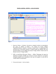
On the Main toolbar, click the Open icon. From the Open dialog box, double-click
on the file Ceramic.tif. The image opens in an image window.
2.
View or change the display parameters for the image as needed.
With the cursor positioned anywhere in the image window, click the right mouse
button to display the Image pop-up menu. Choose Properties to change display
parameters such as the lookup table and the display context.
3.
Select the operator you want to run.
In the Operator dialog box, click the SelectOperator button. From the drop down list,
click Filtering Low Pass ImgLowPass3x3. The Operator dialog box
displays the input and output icons for ImgLowPass3x3.
Æ
04/05/99
Æ
4.
View the online Help for the selected operator.
In the Operator dialog box, click the OperatorHelp button. The Help topic for the
currently selected operator, ImgLowPass3x3, is displayed. To close the Help
window, click the close button in the upper right corner of the Help screen.
5.
Specify the operator parameters, including the input and output images.
In the Operator dialog box, click the input image icon and select the image you want
from the drop-down list (in this case, there is probably only one image listed,
Ceramic.tif). For the output image, use the default New image which is already
selected. There are no other parameters for ImgLowPass3x3.
6.
Run the operator.
On the toolbar at the bottom of the Operator dialog box, click the Run Operator
button. While the operator is running, the stop sign button turns red. You can stop
Aphelion User Guide • 15
the operator by clicking on the red stop sign button. When the stop sign button turns
white, the operator has completed running. View the results (in Image 0).
7.
Select a macro from the list of macros distributed with Aphelion.
On the Objects toolbar, click the Macros button. Choose Macros, then select
Ceramic.apm to open a macro window containing Ceramic.apm.
8.
Run the macro.
On the Macro toolbar, click the Run button. As the macro runs, Aphelion displays
dialog boxes that allow you to select certain features.
9.
View the results in an Aphelion grid document.
On the Objects toolbar, click the ObjectSet List button. Select a grid from the
drop-down list.
10.
Free all open images.
In the Operator dialog box, click the ImgFreeAll button. Aphelion displays a
message box asking you to confirm that you want to free all open images. Click Yes
to free all open images.
Loading and Saving Images
There are three methods for loading images into Aphelion:
•
Load one of the supported file formats (TIFF, BMP, JPEG, KBV)
•
Import an unsupported format
•
Capture a live image
Opening and Saving Images
Aphelion supports the following image file formats:
•
Tagged image file (.tif)
•
Bitmap (.bmp)
•
JPEG (.jpg)
•
KBVision (.im)
To open an image
1.
From the File menu, choose Open Image. The Open dialog box appears, listing all
.tif images available in the Aphelion\Images directory. To change the type of file
listed, click the drop-down arrow in the Files of type field.
2.
Double-click the image you want to load. The image opens in an image window.
The Image toolbar is displayed along the right side of the screen.
Shortcut: To open an image, click
on the Main toolbar or press CTRL+O.
To save an Image
After you make any changes to an image, you must save the image or the changes will be lost
when you exit Aphelion.
16 • Aphelion User Guide
04/05/99
1.
Make sure the image window you want to save is active. To make an image window
active, click on its title bar.
2.
From the File menu, choose Save As Image. The Save As dialog box opens,
listing all .tif images available in the Aphelion\Images directory. You can change the
directory as needed.
3.
From the list of images, choose the one you want to save. (Or type the name of the
file in the File name field.)
4.
Click the Save button. Aphelion displays a message box asking if you want to
replace the existing file of the same name. Click Yes to write over the existing file
or No to cancel.
Shortcut: To save an image, make sure the Image window is active and click
Main toolbar or press CTRL+S.
on the
Other Image Formats
If you have images in a format other than the supported formats (TIFF, BMP, JPG, and KBV),
you can import the images into Aphelion using the AphImgImport operator or a third-party
conversion application.
AphImgImport allows you to read an uncompressed binary file into an Aphelion image. For
example, a SUN raster file can easily be imported into Aphelion using AphImgImport.
To use the AphImgImport operator
1.
2.
3.
Determine the image size, pixel type, and file characteristics of the image you want to
import.
In the Operator dialog box, click the Select Operator button.
Æ
Æ
Click ImageUtilities Input/Output AphImgImport.
Note: You must define the size and type of the output image. In the Operator dialog
box, click the Output image icon, then choose New w/ Options.
To use a conversion program
Several image conversion applications are widely available. To convert a file, first load the
image, and then save it as a TIFF or BMP image.
Image Conversion Application
Company
Graphics Workshop
Alchemy Mindworks, Inc.
HiJaak
Quarterdeck Corp.
Image Alchemy
Handmade Software, Inc.
LView Pro
Leonardo H. Loureiro
PaintShopPro
JASC, Inc.
Acquiring Images
Aphelion has built-in support for several digitizer boards. If you have one of the boards listed
below, you can capture live video at full-motion rate:
•
04/05/99
Imaging Technology, Inc. (ITI) - IC-PCI module (AM-VS, AM-DIG, AM-FA, AMCLR, STD-COMP, STD-RGB)
Aphelion User Guide • 17
•
MuTech, Inc. - MV-1000 (monochrome), MV-1300 (color), IV-450
•
Data Translation, Inc. - DT 3155 (monochrome)
•
Matrox Meteor, Matrox Meteor II, Matrox Meteor/RGB, Matrox Meteor/PPB
•
Matrox Pulsar and Corona for non-standard acquisition
•
Integral Technologies - FlashPoint 128 (monochrome and color)
Note: Aphelion also supports Twain drivers.
Additional hardware support is planned for future Aphelion releases.
To acquire a live image
On the Objects toolbar, click the Camera button.
1.
2.
Select the logical camera you want to use.
In the Operator dialog box, click the Select Operator button.
3.
Æ
Æ
4.
Choose Image Acquisition Grab/Snap ImgSnap.
5.
In the Operator dialog box, click the Acq board drop-down list to select the
acquisition board you want to use.
Run the operator. The image appears in an image window.
6.
Tip
If the Operator dialog box is not visible, click
on the Objects toolbar.
Viewing Images
When you load an image, it is displayed in an image window. The following sections describe
how to investigate image properties through different views of the information in the image.
Image View
The image view can be varied in many ways. This includes zooming, panning, and changing
the display mapping by altering the brightness and contrast or the display LUT.
Tip
•
Zooming and panning
•
Changing the display context
•
Changing brightness and contrast
•
Changing the LUT
•
Resizing an image
You can modify several image characteristics from the Image Properties dialog box.
Click the right mouse button in an image window to display the Image pop-up menu.
Choose Properties Properties. You can get precise information about an
image, as well as adjust its characteristics or presentation properties. For example,
you can change the underlying data type for operators that require input images to be
of a specific data type, or change the lookup table to view fine detail in images that
are too dark or too bright.
Æ
18 • Aphelion User Guide
04/05/99
Histogram
The histogram view shows the gray level histogram for an image. A histogram is useful for
determining which processing and segmentation techniques will be effective. For example, if
the histogram is bi-modal, many of the automatic threshold techniques, such as
AphImgEntropyThreshold or AphImgMaximumContrastThreshold, work well. The histogram
can also indicate digitization problems that may need to be corrected through filtering. For
example, if every odd location in the histogram is zero this may be due to an image with less
than 8 bits per pixel being scaled up to fill 8 bits.
Profile
The profile view shows the intensity surface of an image along one line. This is useful for
examining the sharpness of edges and the signal-to-noise ratio.
Running an Operator
To run an operator, the Operator dialog box must be open in the interface. You then select the
operator you want to run, supply all parameters, including input and output images, and run
the operator.
Tip
If the Operator dialog box is not visible, click
on the Objects toolbar.
Selecting an operator
Operators are selected using a multi-level drop-down list. The first list gives the operator
groups, the next level breaks each group into subgroups, and the final level lists individual
operators.
You can also select an operator from an alphabetical list of all operators by clicking the
A…Z button. For more information, see Selecting an Operator.
To select an operator
Click the Select Operator button.
1.
2.
Move the pointer to the right to display groups, subgroups, and then operators.
3.
Highlight the operator you want and click the left mouse button.
Note: After you select an operator, Aphelion displays check marks next to the selected group,
subgroup, and operator name.
Parameters
You must set the value for each parameter before running an operator. Parameters include:
•
Names of the input and output images
•
The name of the kernel for a convolution
•
The size of the kernel
•
The shape of the structuring element for morphological transformations
Most parameters are set by selecting a value from a drop-down list. Some parameters, such as
strings and numbers, must be typed. For more information, see Selecting Operator
Parameters.
04/05/99
Aphelion User Guide • 19
Tip
Before you run an operator, you must first specify all parameters including any input
and output images.
Advanced Parameters
For some operators, advanced parameters are available. Advanced parameters allow greater
control over processes such as segmentation. If an operator includes advanced parameters, the
advanced parameter button is available.
Click to display the advanced parameters and supply values.
To run an operator
To run an operator, use the toolbar buttons at the bottom of the Operator dialog box.
Button
Function
To run an operator, click the green arrow button.
To cancel the operator while it is running, click the red stop sign button.
When the operation is complete, the stop sign turns white.
Shortcut To run an operator, press CTRL-R.
After running an operator, the output image is displayed (if applicable). See Viewing Images
for information on obtaining different views of the image.
Processing Images
This section describes how to process and enhance images.
Filtering to remove gray level noise
Gray level noise is characterized by varying pixel values. This noise can be random or
regular.
•
Linear or Convolution Filters
Linear filters are the most basic of image processing tools. Depending on the kernel
passed to AphImgConvolve, you can apply a low-pass filter or a high-pass filter to an
image. For removing random gray level noise, use one of the low-pass filters
available in Aphelion, such as AphImgLowPass5x5.
•
Non-linear Filters
Non-linear filters are filters whose output is not proportional to the input. For
example, smoothing by averaging is linear, while median smoothing is not. An
example of a non-linear filter in Aphelion is AphImgMedian. This operator replaces
the central pixel with the median, or middle, value when all the neighborhood values
are ordered from lowest to highest. As with the linear low-pass filters, a larger
neighborhood results in a more uniform output image.
•
Frequency Filters
Frequency filters are useful when you have predictable gray scale noise. It is often
useful to run AphImgFFT to view the power spectrum of the image. If you see well-
K
filtering
20 • Aphelion User Guide
04/05/99
defined clusters which are not near the center of the power spectrum these may be
noise that can easily be removed using one of the frequency filtering operators such
as AphImgLPRectangularFilter.
•
After filtering the power spectrum image, use the AphImgInverseFFT operator to
recreate the gray scale image.
Filtering to remove spatial noise
Some noise is spatial rather than gray level. This noise is characterized by rough boundaries,
or holes in objects. The morphological operators can be very effective at cleaning up this kind
of noise. For instance, AphImgOpen can be applied to a binary, gray scale, or color image in
order to remove outlying fringes of bright objects. AphImgClose can be used to fill in holes in
objects.
Other image processing
The above sections are an introduction to just one section of the operator library in Aphelion.
Here are other image processing sections, with example operators:
•
Arithmetic/Logic (AphImgAdd, AphImgMultiplyConstant)
•
Edge Detection (AphImgSobelEdges)
•
Transforms (AphImgRotate, AphImgRGBToHSI)
•
Acquisition (AphImgSnap)
•
Utilities (AphImgCreateGaussianNoise, AphImgCopy)
Extracting Objects from Images
This section describes how to use Aphelion to measure distances, sizes, and objects in images.
Global Measurements
Global measurements are those computed directly on the image. For example:
Tip
•
Given a binary image, you can compute the number of foreground pixels as the area
of the image. This measurement is computed by AphImgArea.
•
Given a gray scale image, you can compute the sum of all the pixel values as the
volume of the image using AphImgVolume
•
Other global measurements are interactive. For instance, AphImgDistance reports
the length of a line you draw in the image overlay.
When you select a global analysis operator, such as AphImgVolume, the
button
appears in the Operator dialog box. This button allows you to indicate if you want
the output displayed in the Info window. For AphImgHistogram,
AphImgBandHistogram, and AphImgProfile, you can also choose to display the
output in a Profile or Histogram window or export the output to an Excel
spreadsheet.
Calibration
Many global measurements can be computed in physical units, rather than pixels. To do this,
you first need to calibrate the image.
For more information, see Calibrating an Image.
04/05/99
Aphelion User Guide • 21
Segmentation
You may often be interested in individual objects in an image, rather than characteristics of
the overall image. You can define these individual objects using segmentation operators.
The following figures show regions and lines extracted from the same image:
Regions
Lines
Regions are the most common object representation. A region is a set of connected pixels
stored in a bitmap representation. The most basic way to get regions is to threshold the image
using AphImgThresholdObj. This operator is manual, in that you have to specify the low and
high bounds of the threshold. There are also a number of automatic segmentation operators,
such as AphImgEntropyThresholdObj.
Tip
All Aphelion region segmentation operators have two versions, one that ends in
“Obj” and one that doesn’t. The “Obj” operator creates regions within the ISR, while
the others create binary and label images.
Many other object representations are available in Aphelion. The following list gives example
operators for each:
•
Lines (AphImgGradientLines)
•
Edgels (AphEdgesToEdgels)
•
Rectangles (AphLabelsToRectangles)
•
Chains (AphEdgelsToChains)
•
Polygons (AphRegionConvexHullPolygons)
Object Measurements
Object - A region, point,
rectangle, line, edgel, or
chain, and its associated
measurements. One row in an
ObjectSet.
Object measurements are attributes computed for objects such as regions, lines, and
chains. Typically, measurements are computed in order to filter, classify, or quantify
actual objects in the image. Aphelion contains powerful object measurement
database, visualization, and calculation tools.
ObjectSets
ObjectSets are represented in the Intermediate Symbolic Representation (ISR). The ISR is a
database used to store and retrieve object measurements. The easiest way to conceptualize the
ISR is to think of it as a two-dimensional array, just like a spreadsheet. In this analogy, the
rows are objects, and each column represents one specific measurement. The ISR is much
22 • Aphelion User Guide
04/05/99
more than a spreadsheet, though, because it allows for efficient addition and deletion of
objects and measurements (rows and columns), and for spatial access.
There are a number of ISR utility operators, including:
•
AphObjCopy
•
AphObjFilter
•
AphObjRead
Tips
•
To load and save ObjectSets (ISR databases), use the Open ObjectSet command
on the File menu.
•
The Aphelion ISR file format is completely compatible with the KBVision ISR file
format.
•
Using AphObjDraw, you can draw spatial attributes (regions) as an overlay on a gray
level image.
Example
This example describes how to start with an image and produce object measurements in a grid.
1.
Run AphImgThresholdObj to produce region objects in the ISR. To do this, set the
input image from the pulldown list by clicking within the "Input" box, type "regions"
in the "Output ObjectSet" type-in box, and then slide the Low and High threshold
sliders until the desired objects are colored red in the image.
Click the Run Operator button to execute the operator.
2.
Run AphObjComputeMeasurements to compute all the available region
measurements. To do this, select the input image from the pulldown list under
"Input", and then select the region set from the pulldown list attached to the "Input
ObjectSet" parameter.
Click the Run Operator button to execute the operator.
You now have regions in an ObjectSet, with measurements computed for each
region.
3.
On the Objects toolbar, click the Objectset List button to open the grid. Select
Regions.
4.
View the measurements as described in the Grid section.
Grid
Results from an object analysis are automatically saved in an Aphelion grid, or spreadsheet. A
Grid document can be used to display ObjectSet data for analysis and charting.
You can specify whether you want a grid to open automatically each time an ObjectSet is
computed.
•
To open grids automatically when they are computed, choose Preferences from the
Options menu. Make sure that the Automatically display grid option is
checked.
•
If you do not set up grids to open automatically, you can open a grid using the
following procedure.
To view ISR data in a grid
04/05/99
Aphelion User Guide • 23
1.
On the Objects toolbar, click the ObjectSet List button. The pop-up menu lists
the grids that have been created. Each grid has the same name as the corresponding
ObjectSet.
2.
Select the grid you want to open.
The grid can be used to sort, filter, modify, and export measurement data. It can also be used
to select an individual object or a set of objects to view in the overlay. For more information,
see Grid Documents and Message Passing.
Supported Measurements
Aphelion supports a wide range of measurements for objects through the
AphObjComputeMeasurements operator. Given a set of regions, this operator allows you to
compute all or some of the available region measurements. When presented with lines or
another representation, the operator computes the appropriate measurements.
Summary of object measurements:
•
Region location, area, shape, texture, color
•
Line location, length, angle, contrast, color
•
Chain location, length, curvature, contrast, color
•
Polygon location, area, boundary length, color
•
Edgel location, angle, magnitude, color
•
Rectangle location, area, color
See the Help page for AphObjComputeMeasurements for more information about each
measurement.
Tip
Each object representation can be converted to a region using
AphObjSpatialAttributeToRegions. This makes it possible to compute all the region
measurements for objects such as lines, chains, and polygons.
Other object processing operators
The above sections are an introduction to the object operator library in Aphelion. Here are the
other object processing sections, with example operators:
•
Conversion (AphObjSpatialAttributeToRegions)
•
Transforms (AphObjRotate)
•
Morphology (AphRegionErode)
•
Grouping (AphEdgelsToChains, AphRegionSplitConvex)
•
Analysis (AphImgVolume, AphRegionFeret, AphChainAttributes)
•
Utilities (AphObjFilter, AphObjCopy)
Reporting Results
Printing
In Aphelion, you can print individual documents such as images, macros, and charts. You can
also use Print Page Design to compose a printed page with documents and text.
24 • Aphelion User Guide
04/05/99
Focus on the window that contains the document, such as an image or macro, that
you want to print.
Click the Print button on the Main toolbar.
Click the Print Page Design button on the Objects toolbar to open a Print Page
window. Click the right mouse button to display the Print Page Design menu and
add images, charts, and text to the page.
Use the mouse and the pop-up menu to move, resize, and position the elements on
the page. Then click the Print button on the Main toolbar to print the page.
Exporting Object Measurements
You can export object measurements to Excel, Access, or any other Windows program in
order to sort, report, print, or graph results. Use the AphObjExport operator to create a TABseparated ASCII file. This type of file can be imported into Excel, Access, and other
programs using their Insert commands.
For more information, see Exporting Data from Aphelion.
Scripting
BasicScript is a powerful Visual Basic compatible scripting language. Using BasicScript, you
can record sequences of operators, loop over a number of images or objects, access pixels, and
create dialogs.
Note: Macro files have the extension .apm.
Loading a macro
1.
From the File menu, choose New. The New dialog box opens.
2.
Choose Macro Document and click OK to open a macro window.
3.
In the macro window, click the right mouse button to display a pop-up menu.
4.
Choose Load to display the Open dialog box, listing the macros in the macro
directory. Highlight the macro you want to load and click Open.
on the Objects toolbar to display a list of macros in the current macro
Shortcut: Click
directory, as well as options for listing the macro files in the Examples and Macros
directories. Simply click to load the macro you want to use.
Recording a Macro
Each operator you run from the Operator dialog box can be recorded in a macro for saving
and later playback. This is useful for grouping common operations, or for creating an
application macro that performs filtering, segmentation, measurement, and output tasks. For
more information, see Recording a Macro.
04/05/99
Aphelion User Guide • 25
Running and Debugging a Macro
A full BasicScript execution and debug environment is included within Aphelion. This allows
you to run macros, step through the instructions, and watch variable values. This can be used
to catch problems in your macros, or as a demonstration method, where the steps of your
demo are recorded in a macro and executed one at a time. For more information, see Macros.
Creating Dialogs
BasicScript includes a complete dialog building environment. You can create a dialog and
add buttons, type-in areas, pulldown lists, etc. This is useful for creating applications which
present options to the user, such as three filtering options followed by measurement options.
For more information, see Using the Dialog Editor.
Aphelion Macros
The following macros are provided in the standard Aphelion distribution.
•
Example Macros. The example macros provide examples of Aphelion features, such
as file access and global measurements, and are stored in the directory
\Aphelion\Examples.
•
Application Macros. The application macros include image processing examples,
such as color processing and morphology, and are stored in the directory
\Aphelion\Macros.
We recommend that you run each macro and view the results. For an annotated version of
Ceramic.apm, see Getting Started: Annotated Macro (Ceramic.apm).
Tip: To load a macro, click
on the Objects toolbar. The drop-down menu contains
options for the Macros and Examples directories, as well as a list of all the macros in the
default macro directory (determined by the last macro you opened).
•
To load a macro from the Macros directory, choose Macros and then select the
macro you want.
•
To load a macro from the Examples directory, choose Examples and then select the
macro you want.
•
To load a macro from the default macro directory, select the macro from the list at
the bottom of the menu.
For more information, see Loading a Macro.
Example Macros
The example macros are stored in the directory \Aphelion\Examples. To load an
example macro, click the Macros button on the Objects toolbar, then choose Examples.
Select the macro you want from the drop-down list.
26 • Aphelion User Guide
Macro Name
Features highlighted in the macro
BrowseDirectory.apm
Browses an image directory from Visual Basic, looping on
images
ColorImageAccess.apm
Shows how to access pixels in a color image from
BasicScript.
ComplexImageAccess.apm
Shows how to access pixels in a complex image from
BasicScript.
04/05/99
Dialog.apm
Displays a permanent dialog box to run an application
ExportToExcel.apm
Starts Excel and loads an image histogram into a worksheet
ExportToNotepad.apm
Starts Notepad and loads text
ExportToWord.apm
Starts Word and loads an image and text
FileAccess.apm
Demonstrates reading and writing a file from Basic
FrameGrabber.apm
Demonstrates various framegrabber functions
FuzzyClassifier.apm
Calls the Fuzzy Logic Classifier and computes scores from
Basic.
GlobalMeasurements.apm
Computes a number of global image measurements
HistogramAccess.apm
Accesses the histogram values from Visual Basic
ImageAccess.apm
Reads and writes the pixels in an image from Basic
ImageFlickerView.apm
Demonstrates how to toggle the display between two
images to compare them.
ImageRefresh.apm
Turns the display OFF in a macro to save time
ImgBoxes.apm
Turns regions into bounding boxes and filter them
ImgChains.apm
Starts with a gray level image and extract chains
ImgHistogramChart.apm
Uses chart functions to display an image histogram
ImgLines.apm
Starts with a gray level image and extract lines
ImgRead.apm
Prompts the user to select an image, and then loads and
displays the image. This macro can be used as a prefix in
another macro to load an image to process.
LineROI.apm
Creates processing Regions of interest (ROIs) which are
derived from a line object set.
Lines2Regions.apm
Conversion of objects into regions for measurement
purposes
ManageOverlay.apm
Shows how to get coordinates of various objects drawn in
the overlay.
ObjectAccess.apm
Accesses attributes for an ISR object from Basic
ObjHistogramChart.apm
Uses chart functions to display an object histogram.
PrintPage.apm
Demonstrates printing functions from Basic
ProcessDialog.apm
Demonstrates a simple dialog that stays open while buttons
are pressed to perform operations.
RegionMorphology.apm
Morphology performed on ISR regions
RegionRotate.apm
Rotation of ISR objects
Regions2Lines.apm
Fitting lines to ISR regions
ShowImageSequence.apm
Shows how to display a sequence of any 2D images.
ViewManipulation.apm
Moves and resizes image views
Application Macros
The application macros are stored in the directory \Aphelion\Macros. To load an
application macro, click the Macros button on the Objects toolbar, then choose Macros.
Select the macro you want from the drop-down list.
Macro Name
04/05/99
Features highlighted in the macro
Aphelion User Guide • 27
BasicExamples.apm
A variety of useful techniques using Basic
Blood.apm
Basic ISR object creation and measurements
Ceramic.apm
Basic image processing and ISR object techniques
Circuit.apm
Morphological operators to detect the defect
Color.apm
Color processing
Confocal.apm
RGB to HIS conversion
DemoDialog.apm
Dialog presenting a menu of applications demos
DemoLoop.apm
Loops to apply many operators to all images in a directory
FeretAccess.apm
Accesses the Feret diameters in an ISR object
Fourier.apm
Demonstrates various frequency domain filters
Granulo.apm
Granulometry computation, and automatic export to Excel
Grille.apm
ISR measurements and morphological operators
ImgRegister.apm
Registers an input image to a reference image.
Histology.apm
Color processing combined with morphology
ImmunoMarker.apm
Uses color information to detect cells
Muscle.apm
Morphological operators to detect cancerous cells
Road.apm
Computes boundary chains; demonstrates edgels, chains and
lines
RoiProcess.apm
Demonstrates conversion of ISR regions to ROIs
SequenceInterface.apm
Uses a dialog for acquiring a sequence of images
WCCO.apm
Watersheds used to segment a multi-phase image
Annotated Macro (Ceramic.apm)
This macro example is an annotated version of the macro Ceramic.apm. Ceramic.apm is one
of the standard macros distributed with Aphelion. In this macro, the goal is to:
•
Extract all the fibers (dark, circular objects)
•
Measure the surface, elongation and compactness of each fiber
•
Provide the position of the fibers in pixel coordinates
The image, Ceramic.tif, was obtained with a scanning electronic microscope. The pixel values
range from 1 to 255. In this macro, the fibers are segmented from the background using a
threshold. Morphological operators are used to clean the image. Local analysis is performed
to get measurements on each fiber. From the measurement data, the fibers are filtered.
This macro also demonstrates how to use BasicScript, a Visual Basic compatible macro
language, to create dialog boxes. The dialog boxes used in this macro are:
•
YesNoDialog, to specify if the images are deleted at the end of the macro
•
BreakTimeDialog, to specify the time lag between two Aphelion operators
•
FilterBox, to select which filter to apply
Annotated Macro, Ceramic.apm
Note: In this example, the macro code appears in boxes, with the annotations in regular text.
For more information about a specific Visual Basic command, refer to the Macro Language
Reference Guide, available from the Help menu in Aphelion.
28 • Aphelion User Guide
04/05/99
In Visual Basic, all comments made in a macro must start with a quote. An alternative is to use
the rem command.
'----------------------------------------'*
Ceramic.apm
*
'----------------------------------------'* Originator: GG
*
'* Date of creation: 27/01/96
*
'* Date of last modifications: 26/09/96 *
'------------------------------------------
Each subroutine must have a name. In Aphelion, the name by default is main, but any other
name can be given to a subroutine. A subroutine can call another one, if the other subroutine is
placed in the same file.
Sub main
'----------------------------------------'*
Declarations
*
'-----------------------------------------
The following declarations define two integer variables, named breaktime and bt1000.
Dim breaktime As Integer
Dim bt1000 As Integer
The following dialog box is defined using the Dialog Editor. This dialog box lets you delete
all images and ObjectSets after you run the macro. The values 180 and 48 correspond to the
size of the dialog box. The string "Aphelion Dialog Box" is the text which appears in the
dialog box banner.
Begin Dialog YesNoDialog ,,180,48,"Aphelion Dialog Box"
OKButton 132,8,40,14
GroupBox 4,20,108,24,"",.GroupBox1
Text 4,8,108,8,_
"Delete images and ObjectSets?",.Text1
OptionGroup .OptionGroup1
OptionButton 16,32,32,8,"YES",.OptionButton1
OptionButton 72,32,32,8,"NO",.OptionButton2
End Dialog
The variable named ABox is defined as a dialog box of type YesNoDialog.
Dim ABox As YesNoDialog
When this dialog variable is used in a dialog call, it will appear in Aphelion as:
The following is the definition of a dialog box to specify break time. The variables
OptionButton1, 2, 3 will contain the value 0 or 1, depending on the selection. Other
numerical values correspond to the size and position of the OK and option buttons.
04/05/99
Aphelion User Guide • 29
Begin Dialog BreakTimeDialog ,,189,76,"Break Time during the execution"
OKButton 144,8,40,14
GroupBox 4,4,132,68,"",.GroupBox1
OptionGroup .OptionGroup1
OptionButton 16,16,108,8,_
"No break during the execution",.OptionButton1
OptionButton 16,36,116,8,_
"messages displayed during 3 sec.",.OptionButton2
OptionButton 16,56,116,8,_
"messages displayed during 5 sec.",.OptionButton3
End Dialog
The variable named Breakbox is defined as a dialog box of type BreakTimeDialog.
Dim BreakBox As BreakTimeDialog
When this dialog variable is used in a dialog call, it will appear in Aphelion as:
The following is the definition of a dialog box to specify which filters will be performed on
the ISR measurements. This dialog includes 4 check boxes, an OK button, and a Cancel
button. All numerical values correspond to positions in pixels and sizes.
Begin Dialog FilterBox ,,172,100,"Object Filtering"
OKButton 124,8,40,14
CancelButton 124,28,40,14
Text 16,8,92,20,_
"The filtering of the fibers is based on:",_
.Text1,"Arial",9,ebBold
CheckBox 16,36,68,8,"Surface area",.surface
CheckBox 16,52,68,8,"Location",.location
CheckBox 16,68,68,8,"Elongation",.elongation
CheckBox 16,84,68,8,"Compactness",.compactness
End Dialog
The variable named FBox is defined as a dialog box of type FilterBox.
Dim FBox As FilterBox
When this dialog variable is used in a dialog call, it will appear in Aphelion as:
Aphelion supports both 4 and 8 connectivity. The two following variables are used for the
labeling operation, to specify the number of neighbors of each pixel.
30 • Aphelion User Guide
04/05/99
graph4C = AphNgbGraph("2D 4-connected")
graph8C = AphNgbGraph("2D 8-connected")
After all the declarations, the code begins.
'-------------------------------------'*
Main program
*
'---------------------------------------
First, the dialog box to select the time between two operators (break time) is displayed using
the Dialog function and the BreakBox variable. This dialog returns two values, -1 if the OK
button is pressed, or 0 if the CANCEL button is selected. As there is no CANCEL button, the
dialog can only return -1. When the OK button is selected, the variable .OptionGroup1 tells
which option has been selected. This variable can take three values, 0, 1 and 2.
response% = Dialog(BreakBox)
Use the CASE command to test a variable, and to branch to any line depending on the value.
This is useful for handling the different button selections from a dialog.
Select Case response%
Case -1
' OK button
If BreakBox.OptionGroup1 = 0 Then
breaktime = 0
Else If BreakBox.OptionGroup1 = 1 Then
breaktime = 3
Else
breaktime = 5
End If
End If
Case 0
' Cancel button
MsgBox "Cancel button doesn't exist!"
End Select
All times in Visual Basic are given in milliseconds. Thus the number of seconds specified by
the variable .OptionGroup1 is multiplied by 1000.
bt1000 = breaktime * 1000
Load the image ceramic.tif from disk and create a new image in Aphelion, using the
AphImgNew operator. The full path to the image file has to be specified.
original = AphImgNew()
AphImgRead original, "c:\Aphelion\Images\Ceramic.tif"
The MsgOpen command will display a string in a pop-up box. The sleep command creates a
pause depending on the time lapse defined. After opening a message window, you must close
that window using the MsgClose command.
MsgOpen "Composite material in a ceramics matrix", breaktime, False, False
Sleep bt1000
MsgClose
The following are a number of messages to guide the user. The second message asks the user
to specify threshold bounds of 1 and 117. Usually, the call to AphImgThreshold has three
parameters, the two images and the bounds. As one of the three parameters has been omitted,
Aphelion will prompt the user to enter those values. However, Visual Basic does not permit
skipping the first parameters, and then specifying the last ones. If you want to let the user
specify the first parameter, then do not specify any parameters in the call to the operator.
04/05/99
Aphelion User Guide • 31
MsgOpen "The gray level histogram of this image includes two modes",
breaktime, False, False
Sleep bt1000
MsgClose
MsgOpen "A threshold will segment the two phases",
breaktime, False, False
Sleep bt1000
MsgClose
MsgOpen "Specify Low as 1 and High as 117", 0, False, False
Sleep 3000
The following lines show a threshold of the original image into a new image named Binary1.
This name will appear in the window banner, and will also allow the user to work later on this
image. The AphThreshold argument to AphImgThreshold is not specified as described above.
b1 = AphImgNew("Binary1")
AphImgThreshold original,b1
MsgClose
MsgOpen "Interactive gray level Thresholding", breaktime, False, False
Sleep bt1000
MsgClose
The binary image resulting from the threshold includes the fibers and also parts of the
background (the darkest pixels). However, the fibers are much larger than the background
noise, so you can apply a morphological dilation to the original gray scale image (with a
structuring element whose size is greater than the size of the objects in the background, but
smaller than the size of the fibers) to remove the darkest pixels.
The following lines perform a gray scale dilation of size 3, based on a square structuring
element. The dilation is performed on the original image, and the output image is named
Image1.
i1 = AphImgNew("Image1")
AphImgDilate original,i1,AphSElement("Square",3)
A new threshold is performed to extract the core of the fibers. The two bounds are set to 0 and
117. The threshold is performed on the result of the previous dilation, and the output image is
named Binary2. Binary2 contains the seed points for the fibers, but not for the background
noise.
b2 = AphImgNew("Binary2")
AphImgThreshold i1,b2,AphThreshold(0,117)
The following call to AphImgReconstruct performs binary reconstruction of the first binary
image, using seeds detected after the second threshold. The output result will contain all blobs
from the first threshold image which contain one or more seed pixels in the second threshold
image. The binary reconstruction is based on the 4-connectivity, which means that every pixel
in the binary image has four neighbors, in the 0, 90, 180 and 270 degree direction.
b3 = AphImgNew("Binary3")
AphImgReconstruct b1,b2,b3,graph4C
The following call to AphImgFree deletes the first two binary images, Binary1 and Binary2,
which are not needed anymore.
AphImgFree b1
AphImgFree b2
Some of the fibers in the remaining binary image are connected. The use of binary
segmentation operators based upon mathematical morphology techniques will segment all the
fibers. The following lines call AphImgClustersSplitConvex, an operator based on the
watershed algorithm.
32 • Aphelion User Guide
04/05/99
b4 = AphImgNew("Binary4")
AphImgClustersSplitConvex b3, b4, 10, graph4C
Now AphImgHoleFill is used to fill the holes within blobs (fibers) in the previous binary
image.
AphImgHoleFill b4, b4, graph8C
AphImgBorderKill will eliminate the objects intersecting the border of the image (partial
fibers). Notice that both input and output images are identical. This feature is supported by
Aphelion for all the operators which have input and output images of the same type. The
operator is based on 4-connectivity.
AphImgBorderKill b4, b4, graph4C
The following AphImgClustersToLabels operator takes a binary image as input, and generates
a labeled image. In the labeled image, each object has a different gray level value. All the
pixels of the same connected object have the same value. The labels go from 1 to the number
of objects. The first object is the first one hit while scanning the image from top to bottom and
left to right. The connectivity is very important while performing a labeling.
l1 = AphImgNew("Label")
AphImgClustersToLabels b4, l1, AphNgbGraph("2D 4-connected")
AphImgFree b4
After a labeling, you can change the image representation and go from the pixel space to a
symbolic representation. The ObjectSet named FIBERS is created after calling the Aphelion
operator AphImgLabelsObj. The object FIBERS has a spatial representation of the fiber
regions, and a few basic measurements, such as the number of pixels in each region. One way
to examine this data is to use the grid feature available in Aphelion. A grid is similar to a
spreadsheet, where each row corresponds to a label or object, and each column is an attribute
or measurement.
AphImgLabelsObj l1, AphObjNew("FIBERS")
After creating the FIBERS objects, it is possible to analyze each region, and compute their
convex hull from the region representation. This is the best way to compute the convex hull of
objects, from their boundary representation.
AphRegionConvexHullPolygons AphObj("FIBERS")
The object FIBERS can be viewed in the grid, or the boundary of each object can be overlaid
on the original image. The operator AphObjDraw overlays the object FIBERS, seen as
polygons, on top of the image named original.
AphObjDraw original, AphObj("FIBERS"), "POLYGON"
The ObjectSet contains extensive information about the fibers. You can filter the objects
based on their associated measurements, or use AphObjComputeMeasurements to compute
many more attributes of the fibers.
PIXEL_COUNT
04/05/99
Number of pixels within each object
POLYGON.EXTENTS.LL.X
Lower left X coordinates of the polygon extents
POLYGON.EXTENTS.LL.Y
Lower left Y coordinates of the polygon extents
POLYGON.EXTENTS.UR.X
Upper right X coordinates of the polygon extents
POLYGON.EXTENTS.UR.Y
Upper right Y coordinates of the polygon extents
POLYGON.NUMPOINTS
Number of vertices in the convex hull of the object
REGION.EXTENTS.LL.X
Lower left X coordinates of the region extents
REGION.EXTENTS.LL.Y
Lower left Y coordinates of the region extents
Aphelion User Guide • 33
REGION.EXTENTS.UR.X
Upper right X coordinates of the region extents
REGION.EXTENTS.UR.Y
Upper right Y coordinates of the region extents
The FBox dialog box lets the user to select which filter to apply. There are four types of filters
available: surface, location, elongation, compactness.
response% = Dialog(FBox)
Select Case response%
Case -1
' OK button
If FBox.surface Then
i1 = AphImgNew("Surface")
AphImgCopy original, i1
The following line filters the ObjectSet FIBERS into a new ObjectSet named SURFACE. The
attribute involved in the filtering is PIXEL_COUNT. The lower and upper bounds are set
respectively to 1000 and 1400.
AphObjFilter AphObj("FIBERS"), AphObjNew("SURFACE"), "PIXEL_COUNT", 1000, 1400
AphObjDraw will overlay the resulting ObjectSet on top of the original image.
AphObjDraw i1, AphObj("SURFACE"), "POLYGON"
End If
The following lines filter based upon the position of the objects in the image. As the lower
labels are in the upper part of the image, it is sufficient to filter on the TOKEN_INDEX
variable. The two bounds are set to 1 and 10. A new ISR object named LOCATION is
created.
If FBox.location Then
i2 = AphImgNew("Location")
AphImgCopy original, i2
AphObjFilter AphObj("FIBERS"), AphObjNew("LOCATION"), "TOKEN_INDEX", 1,
10
AphObjDraw i2, AphObj("LOCATION"), "POLYGON"
MsgOpen "Selection of the 10 first fibers", breaktime, False, False
Sleep 2000
MsgClose
End If
The following lines filter based on the elongation of the objects. The elongation has to be
measured on the regions, and not the boundaries. The two bounds of the filter are set to 0 and
0.05. A new ISR object named ELONGATION is created.
If FBox.elongation Then
i3 = AphImgNew("Elongation")
AphImgCopy original, i3
AphRegionShape AphObj("FIBERS"), "REGION"
AphObjFilter AphObj("FIBERS"), AphObjNew("ELONGATION"), "ELONGATION", 0,
0.05
AphObjDraw i3, AphObj("ELONGATION"), "POLYGON"
MsgOpen "Fibers with elongation between 0 and 0.05", breaktime, False,
False
Sleep 2000
MsgClose
End If
The following lines filter based on the compactness of the objects. The first call to
AphObjAttributeRatio generates a new attribute named A1 which is equal to the PERIMETER
divided by the AREA of each object. The second call defines a new attribute A2 equal to A1
divided by the PERIMETER, or the AREA divided by the square of the PERIMETER. The
compactness is defined from this ratio. The two bounds of the filter are set to 0.045 and 0.06.
This filter shows how new attributes can be defined from already computed ones. For further
information on creating new attributes from BasicScript see the Obj macro functions. The
final result is displayed on top of the original image.
34 • Aphelion User Guide
04/05/99
If FBox.compactness Then
i4 = AphImgNew("Compactness")
AphImgCopy original, i4
AphRegionShape AphObj("FIBERS"), "REGION"
AphObjAttributeRatio AphObj("FIBERS"), "PIXEL_COUNT", "PERIMETER", "A1"
AphObjAttributeRatio AphObj("FIBERS"), "A1", "PERIMETER", "A2"
AphObjFilter AphObj("FIBERS"), AphObjNew("COMPACTNESS"), "A2", 0.045, 0.06
AphObjDraw i4, AphObj("COMPACTNESS"), "POLYGON"
MsgOpen "Fibers whose shape is close to a circle", breaktime, False, False
Sleep 2000
MsgClose
End If
Case 0
' Cancel button
MsgBox "Cancel button doesn't exist!"
End Select
This dialog box asks whether to delete all the images created by running this macro. The first
choice is the deletion of all the images, and the value of the .OptionGroup1 is then 0. The
variable response% is the returned value of the dialog box.
response% = Dialog(ABox)
If ABox.OptionGroup1 = 0 Then
AphImgFree original
if (i1<>0) then
AphImgFree i1
AphObjFree AphObj("SURFACE")
end if
if (i2<>0) then
AphImgFree i2
AphObjFree AphObj("LOCATION")
end if
if (i3<>0) then
AphImgFree i3
AphObjFree AphObj("ELONGATION")
end if
if (i4<>0) then
AphImgFree i4
AphObjFree AphObj("COMPACTNESS")
end if
AphObjFree AphObj("FIBERS")
End If
This is the end of the macro and the subroutine main. The call to the function End Sub ends
the subroutine.
End Sub
Aphelion Graphical User Interface
The Aphelion graphical user interface (GUI) provides a workspace for displaying images and
other kinds of documents, and the tools to work with those documents. The main workspace
includes a menu bar, Main toolbar, and Objects toolbar. When you first start Aphelion, the
Operator dialog box and tabbed Information/History/Messages window are also open.
You can rearrange elements of the interface to provide more workspace to display images,
charts, and other documents. For information about customizing the workspace, see
Customizing Aphelion.
The Aphelion workspace displays the following types of windows:
•
04/05/99
Image
Aphelion User Guide • 35
•
Acquisition image (for use with cameras)
•
Chart
•
Grid
•
Text
•
Macro
•
OLE
•
Error message
Depending on what type of window is active, the corresponding toolbar is displayed. For
example, when you open an image window, the Image toolbar appears along the right side of
the screen.
Menu Bar
The menu bar runs along the top of the Aphelion screen. The menus provide convenient
access to Aphelion commands.
File Menu
Use the File menu to create a new file, open a file, save a file, print a file, select one of the last
files opened, open and save a project, and exit Aphelion.
The File menu also includes a numbered list of recently opened files. To open one of these
files, type the number or highlight the file and press Enter.
36 • Aphelion User Guide
04/05/99
Edit Menu
Use the Edit menu to work with overlay objects and ROIs.
Use the Cut command on the Edit menu to remove overlay objects and ROIs from an image.
To cut, copy, and paste images, see AphImgCut, AphImgCopy, and AphImgPaste.
Use the Undo command to reverse certain commands or delete the last entry you typed. If the
Undo command is grayed (not available), then you cannot undo the last action.
View Menu
Use the View menu to adjust the way some features of the interface are presented, such as
hiding or displaying toolbars. You can also control the way certain statistics, pixel values, and
output measurements are displayed.
You can:
•
Display or hide toolbars that are displayed in Aphelion. Click to hide or display the
Main toolbar, Objects toolbar, or Status Bar. For more information about adjusting
the workspace in Aphelion, see Customizing Aphelion.
•
Indicate what information should be displayed in the Info Window. For more
information, see Information (Info) Page.
•
Change the language in which the interface is displayed. The Aphelion user interface
currently supports the English, French, and Kanji languages. The menu bar, tooltips,
pop-up menus, operator parameters, and Aphelion messages are translated. For more
information, see Multiple Language Documentation.
Options Menu
Use the Options menu to set Aphelion defaults. Use Preferences to set the default pixel
aspect, to indicate whether images and a history of commands are saved in a project, and to
automatically open the last project when you start Aphelion. You can also control some
display properties, such as whether a grid is automatically displayed when an ObjectSet is
created. For more information, see Preferences.
04/05/99
Aphelion User Guide • 37
Use Charts to specify a model file to be used with a specific type of chart (histogram, profile,
surface map, or scatter plot). For more information, see Creating a Chart Model.
Use Background to set the background color of the Aphelion workspace.
Windows Menu
Use the Windows menu to manage the display of windows in Aphelion. You can use
Cascade to display all open windows in a cascade. You can use the Close command to
close image, chart, or grid windows. The Close command does not apply to macro windows.
The Windows menu also includes a numbered list of open windows. To focus on one of
these windows, type the number or highlight the name and press Enter.
Help Menu
Use the Help menu to access online Help. The Getting Started command takes you directly to
the online version of the Getting Started Guide. The Aphelion Help Topics command displays
the Index tab for all Aphelion online documentation, including the Aphelion Reference Guide
and the Aphelion Developer Guide.
For more information, see Online Help.
Statusbar
The Statusbar provides information about the active window, virtual screen, or interface
element. The information provided is a function of the position of the mouse. You can view:
•
38 • Aphelion User Guide
Quick Help, on the left end of the Statusbar. Depending on where the cursor is
positioned, Quick Help displays:
•
A brief description of a toolbar button or menu item
•
A brief description of each operator listed on the drop-down Operator list in the
Operator dialog box.
•
The position and value of a pixel
•
The position of an ROI or a graphic overlay object
04/05/99
For example, the position and value of a pixel are displayed based on the position of the
mouse cursor. For a color image, the Statusbar displays pixel coordinates and the RGB
values.
Toolbars
Main Toolbar
The Main toolbar is displayed just below the menu bar when you open Aphelion. If you want
to hide the Main toolbar, choose View Main toolbar.
Æ
New Document - Create a new document window. You specify the kind of
document you want to create: macro, grid, text, or OLE.
Open Image - Open a previously saved image.
Save As Image - Save the currently selected image.
Cut - Cut an object and place it onto the Clipboard. You can use the Cut button to
cut information from an image, macro, or text window. You must first select the
material you want to cut before the Cut button becomes available.
To cut information in any tab in the Info/History/Messages window, use the
contextual pop-up menus.
Copy - Copy an object and place it onto the Clipboard. You can use the Copy
button to copy information from an image, macro, or text window. To copy
information in any tab in the Info/History/Messages window, use the contextual popup menus.
Paste - Paste an object from the Clipboard into an image, text, or macro window.
Currently, you can paste overlay objects from an image window or text from a macro
or text window. To paste information in any tab in the Info/History/Messages
window, use the contextual pop-up menus.
Help - Display Aphelion online Help.
Context Help -Display context-sensitive Help for menus, buttons, and other
interface elements. Click this button, then click the object for which you want Help.
Aphelion displays a pop-up window with a brief description of the object. To close
the pop-up window, simply continue with your work.
Objects Toolbar
The Objects toolbar is displayed when you open Aphelion. If you want to hide the Objects
toolbar, choose View Objects bar.
Æ
Operator Dialog Box - Display or hide the Operator dialog box.
Info/History/Messages Window - Display or hide the Info/History/Messages
window.
Print Page Design - Layout images, text, and other objects on a page for printing.
Image List - List the images that reside in all of the virtual screens, and images that
were opened but are now closed. Click the image of interest. If the image was
closed, it will reopen into the virtual screen selected. If the image is open, it will be
04/05/99
Aphelion User Guide • 39
selected.
Graph List - List the graphs and charts that reside in all of the virtual screens, and
charts that were opened but now are closed. Click the chart of interest. If the chart
was closed it will reopen into the virtual screen selected. If the chart is open, it will
be selected.
ObjectSet List - List all ObjectSets that have been created as a result of
segmentation routines.
Camera Definition - Displays a list of camera parameters.
Virtual Screen Filer - Opens a Virtual Screen Filer dialog box with a diagram of the
contents of all virtual screens.
Message Passing - Open the Message Passing dialog box, to set up message passing
between image windows. Currently supported messages are zoom and scroll.
Macros - List macros from the Macros, Examples, or default macro directory.
Modify the Macro Library.
Attach Macro - Open a dialog box that lets you attach up to four macros and up to
two applications to the toolbar.
M1 - M4 - Shortcut button for running a macro. You first must attach a macro to
one of the four buttons using the Attach Macro to Toolbar dialog box.
A1 - A2 - Shortcut button for accessing an application. You first must attach an
application to one of the two buttons using the Attach Macro to Toolbar dialog box.
Show Demos - Play multi-media demos and tutorials that provide an introduction to
Aphelion interfaces, concepts, and algorithms. The files can be played directly from
the CD by dragging one of the .scm files onto the scplayer program. Or, for more
convenience, copy the Demos sub-directory to the Aphelion installation directory in
order to make the demos available from the ShowDemos button.
Image Toolbar
When an image window is active, the Image toolbar appears along the right side of the screen.
The Select Objects and Graphics Overlay buttons are selected by default.
Select Objects - Lets you select an object, and displays handles along the outline
of the object. Overlay objects can be selected in any image window.
Draw Point - Lets you draw a point in any image window. To move a point, first
select it, then drag the point to a new position. For more information, see Point
Overlays.
Draw Line - Lets you draw a line in any image window. To move the line, first
select it, then drag the line to a new position. The Draw Line button is automatically
activated when you click the Profile button.
Draw Rectangle - Lets you draw a rectangle. Rectangular objects may be drawn
(overlaid) onto images. To move the rectangle, first select it, and then drag the
rectangle to a new position. Click the right mouse button to display the rectangle
pop-up menu.
Draw Round Rectangle - Lets you draw a rounded rectangle. Rounded rectangle
objects may be drawn (overlaid) onto images. To move a Round Rectangle, first
select it, then drag the rounded rectangle to a new position. Click the right mouse
button to display the rounded rectangle pop-up menu.
Draw Ellipse - Lets you draw an ellipse. Ellipse-shaped objects may be drawn
(overlaid) onto images. Click the right mouse button to display the ellipse pop-up
menu.
Draw Polygon - Lets you draw a polygon. Polygon objects may be drawn
(overlaid) onto images. Click the right mouse button to display the polygon pop-up
40 • Aphelion User Guide
04/05/99
menu.
Freehand Draw - Lets you draw in an image using a pen. This pen can be used for
changing pixel values, splitting or connecting objects, or marking objects for a
binary and manual segmentation.
Draw Text - Lets you add text to an image. You can set font, text color, and
background color of the text box.
Zoom In- Zoom in on a selected area. Click Zoom In, then draw a rectangle over
the area you want to zoom in on. You can repeat this procedure to zoom in further
on an area.
Reset Zoom - Return an image to its previous magnification. Click the Reset
Zoom button (or press CTRL-Z) as many times as necessary to return to the original
display.
Select Fill Color - Display a dialog box from which you can select a fill color for
drawn objects.
Select Line Color - Display a dialog box from which you can select a line color.
Select Line Width - Display a dialog box from which you can select a line width.
Select Font - Display a dialog box from which you can select a font for the text in
a document (not available).
Overlay - Display a pop-up list of overlay modes:
•
Graphic
•
ROI
•
Profile
•
Histogram
Grid Toolbar
The Grid toolbar appears along the right side of the screen when a grid window is active.
ISR Histogram - Draw a histogram of selected data. Highlight the column in
the Grid that represents the data set (ObjectSet attribute) of interest, then click
. A chart window opens, displaying the histogram.
Sort by Index - Sort the grid by index number (first column).
Sort by Column - Sort the grid by the currently selected column.
ShowInfo - Display the following ObjectSet information in the last five rows
of the Grid: units, minimum, maximum, mean, standard deviation.
Chart Toolbar
The Chart toolbar is displayed along the right side of the screen when a chart window is
active. Charts include histograms, profiles, surface maps, and scatter plots.
Plot - Set the presentation type to a line plot.
Area Chart - Set the presentation type to a filled plot.
3D bar chart - Set the presentation type to 3D bar.
04/05/99
Aphelion User Guide • 41
Move - Move the chart within the chart window.
Scale - Increase or decrease the size of the chart. Click the Scale button, then
drag the cursor up to increase or down to decrease the size of the chart.
Zoom In - Zoom in on a selected rectangular area. Click this button again to
turn off zooming.
Reset - Reset the chart to its original presentation, location, and size.
Macro Toolbar
The Macro toolbar is displayed along the top of the macro window.
Run Macro - Begin execution of a macro.
Stop Execution - Pause execution of a macro. The pointer appears on the line of
code where the macro stopped executing. This is the line of code to be executed
next. Click the Run Macro button to continue execution.
Stop Debug - Stop execution of a macro.
Set/Unset Break Point - Add or remove a breakpoint on a line of code. Click on
any line within the macro and then click on this icon to set a breakpoint. To unset a
breakpoint, click on a line where the breakpoint was already set and click on this
icon.
To clear all break points, right-click in the macro window and choose Debug:Clear
Break Points.
Add Watch - Display the Add Watch dialog box, in which you can specify a
variable. This variable, together with its value (if any), is then displayed in the
watch area of the Macro window. It allows you to check the value of variables for
loops, test conditions, etc.
Step Into - Execute the next line of a macro and then suspend execution of the
macro. If the macro calls another macro, execution will continue into each line of
the procedure.
Step Over - Execute the next line of a macro and then suspend execution of the
macro. If the macro calls another macro, the called procedure will run in its entirety.
Start Recording - Once the record mode has been selected, each action in the GUI
is recorded as a line of Basic code. When you click this button, the current macro
window is cleared and a new macro window appears with the command Sub main.
Be sure the current code has been saved before you record a new macro.
Stop Recording - Stop recording a macro. When you click this button, the
command End Sub is automatically appended to the end of the recorded code.
Keyword Help - Display context-sensitive online Help for macro functions. Make
sure that you click on the command, Aphelion operator, or Aphelion function for
which you want Help before clicking the Help button.
Acquisition Toolbar
Grab Image - Start acquisition of an image.
Freeze Image - Freeze an image.
Snap Image - Snap an image.
Set Gain/Offset - Display the Gain/Offset dialog box and adjust the image in
real time.
42 • Aphelion User Guide
04/05/99
Input LUT - Select the input LUT for a live image.
Statistics on Live Image - Display the mean in the Statusbar.
Histogram on Live Image - Display a histogram of the live image.
Pop-up Menus
In various areas and windows of the Aphelion interface, you can click the right mouse button
to display a pop-up menu. Each pop-up menu lists commands pertaining to the area of the
screen where the mouse cursor is positioned.
Image Pop-up Menu
To display the Image pop-up menu, right-click anywhere in an active Image window.
View
Change the pixel aspect for the active image. Select Pixel=Point, Aspect
Ratio, or Window Size. To change the default pixel aspect, use the
Options Preferences command. See Modifying the Image View and
Modifying the Default Image View.
Æ
For color images, you can also select whether to display all bands
(default), or the first, second, or third bands only.
Properties
Operators
04/05/99
Modify image properties, such as image type, display context, or lookup
table (LUT).
•
Properties (See Image Properties.)
•
Calibrate (See Calibrating an Image.)
•
Contrast/Brightness (See Adjusting the Contrast/Brightness.)
•
Select DC (See Selecting the Display Context.)
•
Select LUT (See Selecting the LookupTable.)
Apply one of the following commands to the active image:
•
Free this image. Free the image from Aphelion memory. See
AphImgFree.
•
Surface Map. Create a surface map. See Image Surface Maps.
•
Histogram. Create a histogram of the entire image. See Image
Histograms.
•
Statistics - Display the following information in the Info tab of the
IHM Window:
•
Minimum
•
Maximum
•
Mean
•
StdDev (Standard Deviation)
•
Skewness
•
Kurtosis
Graphic
Modify properties of the selected graphic. See Graphic Overlays and
Converting Graphic Overlay Objects to ROIs.
ROI
Enable, disable, or delete ROIs associated with the active image. See
Disabling and Enabling an ROI and Deleting ROIs.
Profile
Change the line color of a selected profile line in an image window. See
Modifying an image profile.
Aphelion User Guide • 43
Histogram
Change the line color of a histogram rectangle drawn in an image window.
See Modifying an image histogram.
Grid Pop-up Menu
To display the Grid pop-up menu, right-click anywhere in an active Grid window.
Note: You can also access the Histogram, Sort by Index, Sort by Column, and Show Info
commands from the Grid toolbar. See Grid Toolbar.
Load
Display a list of ObjectSets. Select the ObjectSet you want to load.
Attach to
Graphic
Set up a message passing link between one column (attribute) in the Grid
document and an ISR histogram window. Select a column, then choose
Attach to Graphic. Choose New to create a chart, or select an existing
chart.
Histogram
Draw a histogram of selected data. Highlight the column in the Grid that
represents the data set (ObjectSet attribute) of interest, then choose
Histogram. A chart window containing the histogram opens.
Scatter
Draw a scatter plot, made up of two attributes. The scatter plot is
displayed in a chart window. The title bar of the chart window displays
the name of the grid and the two ObjectSet attributes that the scatter plot is
based on.
Export to
Excel
Create an embedded Excel document and load the ObjectSet data into it.
Delete
Column
Delete any selected columns. You can delete columns of scalar attributes
only. You cannot delete columns containing spatial attributes.
To select a column, click on the heading for the column. To deselect a
column, click on the heading again.
Delete Rows Delete any selected rows. To select a row, click on the index number (first
column) for the row. To deselect a row, click on the index number again.
Keep Rows
Display only the selected rows. To select a row, click on the index number
(first column) for the row. To deselect a row, click on the index number
again.
Caution: Choose Keep Rows only if you have selected one or more
rows. Otherwise, the grid will be cleared and the data will be lost.
Sort by
index
Sort by index number (first column).
Sort by
column
Sort the currently selected column.
Show Info
When this command is checked, the last five rows of the Grid Document
display the following ObjectSet information: units, minimum, maximum,
mean and standard deviation.
Chart Pop-up Menu
To display the Chart pop-up menu, right-click anywhere in a histogram, profile, or surface
map, or scatter plot window.
44 • Aphelion User Guide
04/05/99
Properties
Display the Olectra Chart Control Properties dialog box. You can change
the titles of each axis, the color of the various areas of the chart, and other
aspects of the display. See Setting Chart Options.
Save Model
Save the properties of the current chart as a model. You can use the model
when you create other charts. To specify which model you want to use for
a particular type of chart, choose Options Chart from the Aphelion
menu bar.
Æ
Save Chart
Saves the chart description and the data. For more information, see Charts.
Load Chart
Load a chart file that you previously saved.
Show
Maximum
Mark the peaks of the plot.
Show
Minimum
Mark the valleys of the plot.
Print
Print the chart. Choose from the following options:
•
Same Size
•
Using Width
•
Using Height
•
Best Fit
•
Full Page
Clipboard
Put a copy of the chart on the clipboard.
Save As
Bitmap
Save the chart as a bitmap.
Set Defaults
Set the default for the size and position of a particular type of chart. Move
the window to the size and position you want to establish as the default,
then click Set Defaults Size and Set Defaults Position. You set
the size and position separately. The next time you open a chart of that
type, it will use the default size and position.
Æ
Æ
Note: To save defaults for charts in a project, make sure that you choose
Options Preference from the menu bar, then select Save Images in
the project.
Æ
Selection
When using dynamic coloring, delete or change the color of a selected area
of a chart.
•
Delete selection. Delete the selection where the mouse cursor is
positioned.
•
Delete all selections. Use this command to clear all ranges used in
dynamic coloring. For more information, see Using the Histogram
Command.
•
Color. Change the color of the current selection.
Macro Pop-up Menu
To display the Macro pop-up menu, right-click anywhere in an active macro window.
Note: On some PCs, you may need to right-click in the area of the Macro toolbar to display
the Macro pop-up menu.
Load
04/05/99
Load a macro. You can also use the Macro List button on the Objects
toolbar to load a macro. See Loading a Macro.
Aphelion User Guide • 45
Save
Save a macro. See Saving a Macro.
Save As
Save a macro with a new name. In the Save As dialog box, type the name
of the macro in the File name field. Macro files have the extension .apm.
If you forget to save a macro, Aphelion automatically saves the macro in
the Aphelion\tmp subdirectory. See Saving a Macro.
Edit
Debug
Dialog Editor
Edit a macro. See Editing a Macro for more information.
•
Clear
•
Cut
•
Copy
•
Paste
•
Undo. You can click Undo (or press CTRL+SHIFT+Z) multiple
times to reverse multiple actions.
Debug a macro. See Debugging a Macro for more information.
•
Calls
•
Clear Break Points
Use the dialog editor to create dialog boxes. You can edit an existing
dialog box or create a new one.
•
Edit Dialog
•
New
See Using the Dialog Editor.
Font
Modify the font used in the macro window. You can modify the font for
the entire macro, not for selected text. See Editing a Macro.
Add to Macro
Library
Add the current macro to the Macro Library. The macro library makes it
possible to call one macro from another, or pass arguments to a macro.
See Macro Library.
Find
Find a string in the current macro. If the macro window is selected, you
can also use CTRL-F to open the Find dialog box.
Opening New Documents
You can open a new Grid, Macro, or Text document from the Main toolbar or from the
New command on the File menu.
Note: To open an Image, use the Open Image command on the File menu.
1.
From the File menu, choose New. The New dialog box opens.
2.
Select the type of document you want to open.
3.
•
Grid
•
Macro. This option is especially useful for recording a new macro or for loading
an existing macro (and thereby changing the default macro directory).
•
Text
•
OLE. This option is currently unavailable.
Click OK. The corresponding window opens. At this point, the window is empty.
•
46 • Aphelion User Guide
For macros and text files, you can load an existing file or create a new one.
04/05/99
•
For Grid files, you can load an existing file.
To load an existing file, click the right mouse button and choose Load.
You can also use the following keyboard shortcuts to open an existing document in a new
window:
Document Type
Shortcut
Image
CTRL-O
Macro
CTRL-M
Text
CTRL-T
Aphelion File Extensions
.ap
Project
.apb
History
.apc
Chart model
.apm
Macro
.oc2
2-dimensional chart
.oc3
3-dimensional chart
.rls
Rule Set
.tks
ObjectSet
.txt
Text files
Customizing Aphelion
There are several ways you can customize Aphelion, so that your Aphelion sessions will be as
efficient and productive as possible.
Customizing Your Workspace
•
Customize the list of operators that you use frequently. See List of Frequently Used
Operators.
•
Create custom macro and application buttons. See Attaching a Macro or Application
Button to the Toolbar.
•
Create Chart models for displaying histograms, profiles, surface maps, and scatter
plots. See Creating a Chart Model.
•
Turn off the Tip of the Day.
1. From the Help menu, choose Tip of the day.
2. Clear the Show Tips on Startup check box.
3. Click Close.
•
04/05/99
Hide or display the Operator dialog box and the IHM window
Aphelion User Guide • 47
•
To hide or display the Operator dialog box, click the
toolbar.
•
To hide or display the IHM window, click the
toolbar.
button on the Objects
button on the Objects
•
Change the language in which the Aphelion interface is displayed. See Multiple
Language Documentation.
•
Change the background color of the workspace. See Options Menu.
Startup Options
When you startup Aphelion, you can specify that you want to:
•
run a specific macro automatically
•
open Aphelion in a maximized window
•
load the last project you were working on
Running a Macro
You can set up Aphelion so that it runs a macro each time you start the application.
1.
Create a macro named Aphelion.apm.
2.
Save the Aphelion.apm file in the Aphelion\Macros directory.
The next time you start Aphelion, the macro will run automatically.
Starting Aphelion in a Maximized Window
If you want the Aphelion window to open maximized each time you start Aphelion, make the
following change to the Registry.
Note: Changing the Registry is recommended for advanced Windows users only.
1.
Click Start:Run. Choose or type Regedit.
2.
Choose HKEY_CURRENT USER. Then choose Software ADCISAAI Aphelion 2.3 Format Aphelion.
3.
In the right pane of the Registry window, right-click and choose New DWORD
Value.
4.
Type Maximize as the name for the new value.
5.
To maximize the Aphelion window on startup, right-click on the name Maximize and
choose Modify.
6.
Type 1 in the Value Data field. (To change back to the default position, type 0.)
7.
Click OK. The next time you start Aphelion, it will open as a maximized window.
Æ
Æ Æ
Æ
Æ
Æ
Loading a Project
You can set up Aphelion so that the project you were working on when you exited Aphelion
will be opened automatically when you restart Aphelion.
48 • Aphelion User Guide
04/05/99
1.
From the Options menu, choose Preferences. The Preferences dialog box is
displayed. The section for setting Project preferences is at the bottom of the dialog
box.
2.
Select the option, Automatically load the last project.
3.
Click OK.
Preferences
From the Options menu on the Main toolbar, you can specify preferences for how images are
displayed in Aphelion and for how you use projects.
•
Default Image View
•
Project Preferences
For more information about viewing an image, see Image Views.
For more information about projects, see Aphelion Projects.
Modifying the Default Image View
When you first start Aphelion, the default image view is set to maintain the aspect ratio of
images. This means that all images are opened with the image view set to Aspect Ratio.
You can modify the default image view at any time.
Note: To change the image view for a specific image, use the View command on the Image
pop-up menu. See Resizing an Image.
To modify the default image view
04/05/99
1.
From the Options menu, choose Preferences. The Preferences dialog box is
displayed. The section for setting the Default Pixel Aspect is at the top of the dialog
box.
2.
Click the radio button to choose one of the following options:
Aphelion User Guide • 49
3.
•
To indicate that an image window cannot be resized beyond the pixel size of its
x and y axis, choose Pixel=Point. If the size of the window is smaller than the
size of the image, scroll bars will be displayed.
•
To maintain the aspect ratio of the image, choose Aspect Ratio.
•
To allow each axis of the window to be resized independently, choose Window
Size.
Click OK.
Setting Project Preferences
Use the Preferences dialog box to customize what is saved in a project file. For example, you
might choose not to save images in projects if you want to save disk space.
To set project preferences
1.
From the Options menu, choose Preferences. The Preferences dialog box is
displayed. The section for setting Project preferences is at the bottom of the dialog
box.
2.
Select or clear the following options:
3.
•
Automatically load the last project. If you select this option, Aphelion
automatically loads the last project you were working on. If you do not select
this option, the untitled.ap project is loaded. Default: Off
•
Save Images in the project. Default: Off
•
Save Command History in the project. Default: Off
•
Automatically display grid while running an AphObj operator. Automatically
open a grid when you run an operator that creates an ObjectSet. Default: Off
•
Display image thumbnails. This option allows you to display images as
thumbnails in the Operator dialog box. If you are dealing with large images, turn
off this option to improve processing time. Default: On
Click OK.
Note: If you save images and history in the project file, you may notice that it takes a long
time for Aphelion to start. This may mean that the project file has become too large. You
should clear the History pane and the saved images:
50 • Aphelion User Guide
•
To clear the history, right-click in the History pane and select Clear.
•
To clear the images, run AphImgFreeAll from the Operator dialog box, then exit
Aphelion.
04/05/99
Operator Dialog Box
The Operator dialog box is used to apply Aphelion operators to images and symbolic data
sets. The Operator dialog box is open when you first start Aphelion.
Use the ShowOpDialog button on the Objects toolbar to hide or display the Operator
dialog box. You can use the mouse to drag the Operator dialog box to a different location.
The Operator dialog box cannot be resized.
Displaying Results for Global Analysis Operators
When you select a global analysis operator, such as AphImgVolume, the
button appears in
the Operator dialog box. This button allows you to indicate if you want the output displayed
in the Info window. For AphImgHistogram, AphImgBandHistogram, and AphImgProfile, you
can also choose to display the output in a Profile or Histogram window or export the output to
an Excel spreadsheet.
Example
1.
Select AphImgHistogram.
Click the Results button.
2.
3.
4.
04/05/99
Choose one or more of the options:
•
View Output in Info Window
•
Create Profile/Histogram Window
•
Export to Excel
Click the Run Operator button to run the operator. The results will appear
according to the options you chose.
Aphelion User Guide • 51
Note: When you choose an input image for AphImgProfile, the chart window is displayed
automatically. If you chose Export to Excel, you must click the Run Operator button to export
the results to an Excel spreadsheet.
Running an Operator
The following procedure outlines the steps to select and run an operator.
Note:
To interrupt the execution of an operator, click the Stop Operator button. When
the Stop Operator button turns white, the execution is complete.
1.
Open the images you want to work with.
2.
Select an operator. To view online Help for the currently-selected operator, click
in the Operator dialog box.
3.
Specify an input image and an output image.
You can click the image icons and select an image from the pop-up list, or use the
drag-and-drop feature from the Virtual Screen Filer.
Note: If you do want to display images as thumbnails in the Operator dialog box,
choose Preferences from the Options menu and deselect Display image
thumbnails. This is especially useful when dealing with large images.
4.
Make any necessary changes to the parameters. The input and output images you
select may affect the default values of the parameters, as well as the valid ranges or
constraints. Most parameters are set to default values which you can modify.
5.
To run the operator, click the Run Operator button. The progress bar indicates
the status of the Operator execution.
Shortcut: To run an operator, press CTRL-R.
6.
View the results.
For global analysis operators, you can choose to view the results in the Info tab of the
IHM window, in a chart, or in an Excel spreadsheet.
Operator Toolbars
The Operator dialog box has two toolbars; one at the top of the dialog box and one at the
bottom.
The buttons in the toolbar at the top of the Operator dialog box are used to select operators
and to access Help for the current operator.
Frequently Used Operators - Maintain or use a list of frequently used
operators.
ImgFreeAll - Run the ImgFreeAll operator. Aphelion displays a message box
asking you to confirm that you want to delete all open images. Click Yes to
free all open images.
Operator Help - Access online Help for the currently selected operator.
Select Operator (alphabetical) - Display a dialog box for selecting an
52 • Aphelion User Guide
04/05/99
operator from an alphabetical list.
Select Operator - Display a series of menus, with Operator categories and
subcategories, for selecting an operator.
MMX - If you use a PC with an MMX chip from Intel, some Aphelion operators
will execute on the MMX. Use of the Intel MMX coprocessor will dramatically
improve the speed of these operators. If an operator can run on the MMX, a
flag icon appears in the right corner of the Operator dialog box. The user may
select either to run the operator in the MMX, or in the general purpose
processor of the PC.
To use MMX acceleration, an optional extension has to be installed from the
Aphelion Setup menu. Please see the “Release Notes” for more information on
the MMX installation.
The toolbar buttons at the bottom of the Operator dialog box are used to run an operator.
Run Operator - Run the currently selected operator. All parameters must be
defined before you run the operator. As a shortcut, press CTRL-R.
Stop Operator - Click this button, if it is red, to stop any on-going process.
Advanced Parameters - Display advanced parameters for the selected
operator. This button is grayed if there are no advanced parameters for the
selected operator.
Add to History - Add the operator call to the History page without executing
the operator.
The panel in the middle of the toolbar displays the progress of the operator
execution.
Selecting an Operator
From the Operator dialog box, you can select an operator in the following ways:
Select an operator from a list of the entire Aphelion
Operator Library, organized by category.
Select an operator from an alphabetical list of all operators.
Create a list of operators that you use frequently, and select
an operator from that list.
Selecting an Operator from the Aphelion Library
04/05/99
1.
In the Operator dialog box, click the Select Operator button. Aphelion displays
a list of operator groups.
2.
Select the group you want and move the mouse to the right. The second level of
categories is displayed.
3.
Select the sub-group you want and move the mouse to the right.
Aphelion User Guide • 53
4.
To view Quick Help for an operator, move the cursor over the name of the operator.
A one-line description of the operator appears on the left side of the Statusbar at the
bottom of the Aphelion screen.
5.
Click the operator you want to use. The operator name and parameters, including
Input/Output boxes for images, are displayed in the Operator dialog box. If more
than one input or output image is required for an operator, multiple boxes are
displayed.
Note: After you select an operator, Aphelion displays check marks next to the selected
group, sub-group, and operator name.
Selecting an Operator from an Alphabetical List
1.
In the Operator dialog box, click the A..Z button. The Operator Selection
dialog box appears:
2.
Locate the operator you want to select.
3.
•
In the blank field, type the first letter or letters of the operator. Do not type the
prefix “Aph”. The list of operators automatically refreshes as you type.
•
If necessary, use the scroll bars to scroll through the list of operators.
Click OK or press Enter to select the operator you want.
Note: To locate an operator by a specific group, click the drop-down list next to the Group
field and select the group. To further narrow the list, select a Sub Group from the drop-down
list next to that field.
54 • Aphelion User Guide
04/05/99
List of Frequently Used Operators
To create a customized list of frequently used operators
1.
From the Operator dialog box, select an operator in one of the following ways:
•
•
2.
3.
Select an operator from a list of the entire Aphelion Operator Library,
organized by category.
Select an operator from an alphabetical list of all operators.
Click the Frequently Used Operators button.
Click Add to add the currently selected operator to the list.
To select an operator from a list of frequently used operators
1.
2.
In the Operator dialog box, click the Frequently Used Operators button.
Click to select the operator you want to use.
MMX Operators
Aphelion 2.3 supports the MMX chip from Intel. This chip dramatically improves the
speed of Aphelion operators. If an operator can run on the MMX, a flag icon appears in the
right corner of the Operator dialog box. You can run the operator in the MMX or in the
general purpose processor of the PC.
Note: To use MMX acceleration, an optional extension has to be installed during Aphelion
setup. Please see the “Release Notes” for more information on the MMX installation.
The following operators are currently implemented on the MMX:
04/05/99
•
AphImgAdd
•
AphImgSubtract
•
AphImgMaximum
•
AphImgMinimum
•
AphImgMultiply
•
AphImgThreshold
•
AphImgDilate
•
AphImgErode
•
AphImgConvolve
Aphelion User Guide • 55
•
AphImgOpen
•
AphImgClose
•
AphImgWhiteTophat
•
AphImgBlackTophat
Selecting Input and Output Images
If you select an operator that requires input or output images, Aphelion displays input and
output boxes in the Operator dialog box. If multiple input or output images are required,
multiple boxes are displayed. You must specify an image for each box.
Note: To improve processing time for large images, you can turn off the display of input and
output images as thumbnails. From the Options menu, choose Preferences. In the
Preferences dialog box, deselect Display image thumbnails, then click OK.
Based on the input and output images you select, Aphelion supplies default values for the
other parameters.
Selecting an Input ImageX
1.
In the Operator dialog box, click the input image box. A list of open images appears.
Based on the task to be performed, only the relevant input images appear in the list.
2.
Click the image you want to use for the input image.
3.
After you select an image, the input box displays an image pattern similar to the
actual image. If you turn off Display image thumbnails in the Preferences dialog
box, a generic image icon is displayed.
Note: You can use drag-and-drop to select the image you want. From the Aphelion
workspace, drag the image to the input icon.
Selecting an Output Image
Aphelion automatically specifies the output image name. You can change that default using
the New w/Options command on the output image menu. See Modifying an Output Image.
1.
56 • Aphelion User Guide
In the Operator dialog box, click the Output icon. The output image menu appears.
It lists open images, and displays a check mark next to New Image by default.
04/05/99
2.
Use the default New Image or select an image from the list of existing images.
•
If you select New Image, the new image icon appears as the output icon. You
can modify the image data type, size, or name of the image.
•
If you select an existing image, the output icon displays an image pattern similar
to the actual image.
Note: You can use drag-and-drop to select the image you want. From the Aphelion
workspace, drag the image to the input icon.
Modifying an Output Image
04/05/99
1.
In the Operator dialog box, click the Output icon. Make sure that New Image is
selected.
2.
Click New w/ Options… to display the Output Image Options dialog box.
Aphelion User Guide • 57
3.
4.
For each of the following categories, you can modify the values or “Let Aphelion
decide” the appropriate value.
•
Image Data Type. Click the Specify Type radio button, then click the dropdown arrow and select a data type from the list.
•
Image Size. Click the Specify Size radio button, and indicate the number of
dimensions (2 or 3) and make any necessary changes to the image size.
•
Image Name. Click the Set Name radio button and type the name you want
to use for the output image.
Click OK.
Changing the Default Name of the Output Image
You can change the default name of the New Image output from “Image” to another name.
1.
Using WordPad or any other text editor, open the file StdMessages.txt in the
appropriate language directory under Aphelion/Language.
2.
Search for the string “newImNameS=Image %1”.
3.
Change the word Image to the default name you prefer.
Selecting Operator Parameters
After you select an operator, the Operator dialog box displays drop-down lists and sliders for
selecting image and parameter values. Aphelion supplies default values for many parameters;
for others, you must supply the values. For information about setting parameters for specific
operators, see the Aphelion Reference Guide.
Note: You must specify all parameters before you can run an operator.
{bml op_Parms.bmp}
{bml op_Parms2.bmp}
Parameters for AphImgMorphGradientEdges
Parameters for AphImgThreshold
Kernel Editor
The kernel editor is used to modify a kernel or a structuring element (SE). You can define a
kernel or structuring element, name it, enter its name in a list, and save it. Kernels and
structuring elements are saved with the project file.K
•
For convolution, you can modify the value for each element of the kernel.
•
For morphological operators, you can modify the structuring element (SE). In this
case, only the value X can be entered on each point of the structuring element.
Editing a kernel or structuring element
The Kernel Editor button is displayed in the Operator dialog box if the operator you have
selected uses a kernel or structuring element.
1.
K
In the Operator dialog box, click the Kernel Editor button to open the
Structuring Element editor dialog box.
structuring elements
58 • Aphelion User Guide
04/05/99
2.
Define the size of the kernel or structuring element (SE). There is no limit on the
size. To change the size, type values in the X and Y fields under Size. Click
Update/Reset.
3.
Define the origin of the kernel or structuring element. The origin defines which
output pixel is set relative to the position of the kernel. Changes to the origin have
the following effects:
•
Reducing the x position of the origin moves the output pixel values to the left.
•
Reducing the y position moves the output pixels up.
To change the origin of a kernel or structuring element, type values in the X and Y
fields under Origin. The origin can be placed anywhere inside the kernel.
3.
4.
Enter values.
•
For a convolution, click in each box, and enter values (integer or floating point).
•
For a structuring element, click in each box until you get the adequate value.
After defining a kernel or SE, you can type a name in the Kernel Name field. Click
the Add button to add the kernel or SE to a list.
If the kernel or SE already exists in the list, just pull-down the list and select it.
5.
After defining a kernel or SE, click OK. The name of the kernel appears in the
Operator dialog box.
Neighborhood LUTs
Thinning and thickening operations in Aphelion are performed using a lookup table (LUT). A
structuring element generates a family of LUTs with entries ranging from 0 to 511. Depending
on the configuration of the structuring element, and the type of operation, the output of the
LUT is 0 or 1.
By default, Aphelion supplies two predefined LUTs for the Neighborhood Lut Editor:
•
L-Skeleton-8C
•
L-Skeleton-4C
These LUTs correspond to the L configurations for the structuring elements associated to the
skeleton, in 4 and 8 connectivity. You can use the system-supplied LUTs by selecting one
button. Any defined
from the drop-down list, or create additional LUTs by clicking on the
structuring element and its associated LUT is saved in the current project, with the name you
supply.
When you create a new Neighborhood LUT, you can define the exact configuration of the
structuring element.
System-Defined Neighborhood LUTs
Following is a list of the system-defined neighborhood LUTs. These LUTs may not all be
available for some operators..
04/05/99
•
End Points 8-c
•
End Points 4-c
•
Multiple Points 8-c
•
Multiple Points 4-c
Aphelion User Guide • 59
•
Single Points 8-c
•
Single Points 4-c
•
Boundary 8-c
•
Boundary 4-c
•
Centroid 8-c
•
Centroid 4-c
•
Pruning 8-c
•
Pruning 4-c
•
Pruning 8-c(Homotopic)
•
Pruning 4-c(Homotopic)
•
L-Skeleton-8C
•
L-Skeleton-4C
•
SKIZ 8-c (Skeleton by Zone of Inference)
•
SKIZ 4-c
Selecting a Neighborhood LUT
1.
Select an operator that uses a Neighborhood LUT, such as ImgThin or ImgThicken.
2.
In the Operator dialog box, select the input image. The input image must be a binary
or gray scale image.
3.
In the Type field, click the drop-down arrow and select a Neighborhood LUT from
the list. Make sure you have first selected an input image.
Creating a Neighborhood LUT
1.
60 • Aphelion User Guide
Select an operator that uses a Neighborhood LUT.
•
ImgThin
•
ImgThicken
•
ImgHitOrMiss
•
ImgConstrainedThin
•
ImgConstrainedThicken
•
ImgThinSkeleton
•
ImgThickenSkeleton
2.
In the Operator dialog box, select the input image. The input image must be a binary
or gray scale image.
3.
Click the
4.
In the Neighborhood LUT Editor dialog box, enter a name for the Neighborhood
LUT in the Name field.
5.
In the upper left side of the dialog box, enter the values for the structuring element.
Click to toggle between 0, 1, or X.
button to open the Neighborhood LUT Editor dialog box.
04/05/99
6.
When you have finished entering the values for the SE, click the right arrow button
. The values are listed in the box on the right. (To edit an existing
Neighborhood LUT, click on the LUT in the box on the right, then make any changes
to the SE configuration on the left.)
7.
Enter additional SEs if necessary. The morphological operations will alternate
between the SEs.
8.
Indicate whether the SE will be rotated.
9.
•
no rotation
•
4 rotations (90 degree rotation after each iteration)
•
8 rotations (45 degree rotation after each iteration)
In the Operations allowed section, indicate what operations will be allowed.
•
Thinning (central pixel of the SE will be set to 0)
•
Thickening (central pixel of the SE will be set to 1)
•
Skeleton (thinning or thickening till idempotence)
•
Hit or miss (if the configuration is found, the central pixel is then set to 1;
otherwise, it is set to 0).
10. If you want to use In Place substitution, check that box at the bottom of the dialog
box. This option allows you to define whether the operation is performed as a
recursive operation (if the box is checked) or not (the box is not checked). A
recursive operation is one in which the modified pixel is immediately used for the
next pixel in the neighborhood.
11. Click OK to create the neighborhood LUT. The Neighborhood LUT is saved with
the current project.
Modifying a Neighborhood LUT
To delete an SE Configuration Neighborhood LUT
1.
Select the name of the Neighborhood LUT from the drop-down list.
2.
Click the
button.
To delete an SE in the Neighborhood LUT Editor dialog box
1.
Select the SE in the list box on the right side of the dialog box.
2.
Click the
button.
Info/History/Messages (IHM) Window
When you first start Aphelion, the IHM window is displayed in the lower right-hand corner of
the interface.
04/05/99
Aphelion User Guide • 61
The tabs in the Info/History/Messages window let you access the following information:
•
The Information (Info) tab displays pixel values, output of measurements, and other
statistics.
•
The History tab displays a list of executed operators and their parameters.
•
The Messages tab displays information about non-critical error messages.
Tip: To display or hide the IHM window, click
on the Objects toolbar.
Information (Info) Page
The Info page can display the following information:
•
Pixel coordinates and pixel values
•
Location of mouse cursor
•
Histogram values
•
ROI coordinates
•
Global measurements
•
Other information generated by an Aphelion operator
Note: Information displayed in the Info page can be saved to a file. To save the information
to a file, click the right mouse button in the Info page and choose Save or Save As.
Use the View menu on the Aphelion menu bar to indicate what information is displayed in the
Info page.
62 • Aphelion User Guide
04/05/99
Displaying information in the Info page in the IHM window
When you display information in the Info page in the IHM window, you can then save that
information, or copy it to a macro or other document.
1.
From the View menu, choose Info Window Output.
2.
Choose the type of information you want to display.
•
All Information - Display pixel coordinates, chart coordinates, overlay
information, and measurements from global analysis operators
•
Pixel Values - Display pixel coordinates only
•
Histogram/Profile Values - Display chart information (from a profile line or
histogram)
•
Overlay Coordinates - Display overlay information, such as the pixel
coordinates of an ROI
Saving information to a file from the Info page
Information displayed in the Info page of the IHM window can be saved to a file.
1.
From the View menu, choose Info Window Output.
2.
Choose what type of information you want to display in the Info page.
3.
Run or execute Aphelion processes, display histograms, or compute other
information. The values from the operations are displayed in the Info page.
4.
Click the right mouse button in the Info page to display the pop-up menu.
5.
Choose Save or Save As.
History Page
The History page displays a batch file of activities. When an operator is executed, a line
appears in the History page describing the type of operator used, the names of the input and
output images, and the parameters or arguments of the operator.
You can specify whether you want to save the history for the current Aphelion session, or for
the current project. Use the Options Preferences command from the menu bar to display
the Preferences dialog box and make one of the following specifications:
Æ
•
To save history for the current project, select Save Command History in the
project.
•
To display history only for the current Aphelion session, make sure that Save
Command History in the project is not selected.
Running One Line of Code
You can use the editing bar at the bottom of the History page to edit and execute a line of
code. Click the line you want to run. The line appears in the editing bar.
•
04/05/99
To edit the code, click within the line and type. You can use keyboard editing
shortcuts such as CTRL+C for copy and CTRL+P for paste.
Aphelion User Guide • 63
•
To run the code, click the R button at the right end of the editing bar.
Running Multiple Lines of Code
You can also highlight and run multiple lines of code from the History page. Click to
highlight the lines you want to run, then click the right mouse button to display the pop-up
menu. Choose Execute to run the selected lines of code.
Copying Lines of Code to a Macro
Selected lines can be copied from the History page and pasted into a macro window.
Highlight the lines you want to copy, then click the right mouse button and choose Copy or
Cut.
Note: To display a pop-up menu for loading, saving, and modifying information, right-click
anywhere in the History page.
Messages Page
The Messages page displays error messages that are not critical to continuing your work in
Aphelion. Critical error messages are displayed in a Error Message windows.
Virtual Screens
Aphelion supports multiple screens, called virtual screens. This feature allows you to display
multiple Aphelion objects in the same environment. Each tab at the bottom of the screen
represents a virtual screen. You can bring a virtual screen to the top by clicking on its tab.
You can display the following objects in virtual screens:
•
64 • Aphelion User Guide
Images
04/05/99
•
ObjectSets
•
Grid Documents
•
OLE Objects
•
Macros
•
Text
•
Charts
Note: To open up more space for displaying images and other objects, you can hide the
Operator dialog box and the Info/History/Messages window.
•
To hide the Operator dialog box, click
•
To hide the IHM window, click
on the Main toolbar.
on the Main toolbar.
To display them, click the buttons again.
Adding and Deleting Virtual Screens
When you first start Aphelion, there is only one virtual screen and virtual screen tab, labeled
Screen 1. You can create additional virtual screens.
To add a virtual screen
1.
In the Virtual Screen tab area at the bottom of the Aphelion window, click the right
mouse button.
2.
Choose Add. A new tab, representing a new virtual screen, is added at the end of the
row of tabs.
Note: When you exit Aphelion, the names of virtual screens, but not the content, are saved in
the configuration file.
To delete a virtual screen
1.
Position the cursor on the tab for the virtual screen you want to delete.
2.
Right-click to display the pop-up menu.
3.
Choose Delete.
To insert a virtual screen
1.
Position the cursor on the tab to the left of where you want to insert a tab for a new
virtual screen.
2.
Right-click to display the pop-up menu.
3.
Choose Insert.
Virtual Screen Filer
Use the Virtual Screen Filer to:
04/05/99
•
Display a diagram of the contents of all virtual screens
•
Rename any of the virtual screen tabs
Aphelion User Guide • 65
•
Rearrange images or other objects within a virtual screen
•
Drag images to the Operator dialog box
The example shown below has three virtual screens named: Original, Tab1, Tab2. The virtual
window named Original contains two objects, an image and a macro window.
To display or hide the Virtual Screen Filer, click the Virtual Screen Filer button.
The Virtual Screen Filer supports drag-and-drop editing. You can move objects from one
virtual screen to another, and you can move objects from the Virtual Screen Filer to other
areas of the interface, such as the input and output images in the Operator dialog box.
Note: To display a pop-up menu of Virtual Screen Filer options, click the right mouse button
anywhere in the Virtual Screen Filer area.
To rename a virtual screen tab
On the Objects toolbar, click the Virtual Screen Filer button.
1.
2.
Highlight the tab that you want to rename.
3.
Click again on the tab until you see the blinking cursor.
4.
Type the new name for the virtual screen tab.
5.
Press Tab.
Aphelion Projects
An Aphelion project stores images, image settings, and other information such as virtual
screen names. You can use an Aphelion project file to save information and settings specific
to a particular task you are working on. For example, in one project you can save everything
you’ve done on a quality control application and in a second project you can save your work
for a presentation.
The name of the current project file is displayed in the Aphelion title bar. A project file
always has the extension .ap.
66 • Aphelion User Guide
•
When you start Aphelion, it opens with an empty project by default.
•
If you want to automatically reload the last project each time you start Aphelion, use
the Options Preferences command to select the option Automatically load
the last project in the Preferences dialog box.
•
When you exit Aphelion, a message box appears asking if you want to save the
current project in a file. Click Yes to save the project, No to exit without saving
changes to the project, or Cancel to return to Aphelion without saving the project.
Æ
04/05/99
Creating a Project File
Each time you use Aphelion to start a new project, you should start a new project file. That
way, you can easily switch between projects and maintain the information you need for each
project.
Note: When you first start Aphelion, it opens with an empty project unless you have selected
Automatically load the last project from the Options Preferences command.
Æ
To start a new project file from an empty project
1.
From the File menu, choose Save Project As. The Open dialog box is displayed.
2.
Type a name for the project file in the File name field. Project files have the
extension .ap.
3.
Click Save. The name of the project (along with the name of the window that is
currently active in Aphelion) is displayed in the title bar of the main Aphelion
window.
To start a new project file (when another project file is loaded)
1.
From the Options menu, choose Preferences.
2.
Make sure that Automatically load the last project is not selected.
3.
Exit Aphelion, then restart it. Aphelion opens with an empty project.
4.
Create your new project and choose File Save Project As to save it.
Æ
Opening a Project File
Use this procedure to open an existing project file.
1.
From the File menu, choose Open Project.
2.
Select the project file that you want to open. Project files have the extension .ap.
3.
Click Open.
Elements Saved in a Project File
Aphelion stores the following information in the project file:
04/05/99
•
General settings, such as the pathnames for image, macro, and project directories
•
Images
•
Image aspect - (Pixel=Point, Aspect Ratio, or Window size)
•
Display Context (global and image)
•
Kernels (user-defined)
•
Structuring Elements (user-defined)
•
Units (user-defined)
•
Lookup Tables (LUT) (global and image)
•
Neighborhood Lookup Tables (used by thinnings, skeletons, etc.)
•
Virtual Screen names
Aphelion User Guide • 67
•
IHM window settings, including the command history
•
Operator dialog box settings, including the List of Frequently Used Operators
•
Chart model files - used to create histograms, profiles, surface maps, and scatter
plots
•
General information such as the automatic opening of grids, and the display of
image icons
Æ
When you open a project by clicking File Open Project from the menu bar, you can
reopen the images associated to the project by clicking the Image List button on the Main
toolbar, and then clicking on each image name.
Note: ObjectSets are not saved in a project file.
Images
Most Aphelion operators can be used on a wide variety of image formats, including
monochrome or color images, binary, 8-bit, 16-bit, 32-bit and 64-bit images, and integer and
float images.
Image File Formats
Aphelion supports the following image file formats:
•
Tagged image file (.tif)
•
Bitmap (.bmp)
•
JPEG (.jpg)
•
KBVision (.im)
To import files in other formats, use the Aphelion operator AphImgImport or a third-party
conversion tool. You can also acquire live images using a camera.
TIFF files
Aphelion supports reading and writing of TIFF 6.0 Baseline image files. Multiple page and
Tiled TIFF images are not currently supported. Aphelion can read both uncompressed and
certain types of compressed TIFF files. The following compression types are supported for
read only:
•
CCITT Group 3 1-Dimensional Modified Huffman RLE
•
CCITT Group 3 Fax encoding
•
CCITT Group 4 Fax encoding
•
PackBits (Macintosh RLE)
Aphelion writes only uncompressed TIFF files.
In addition, Aphelion supports the following extensions to TIFF 6.0 Baseline:
•
68 • Aphelion User Guide
Data Sample Format - Aphelion supports reading and writing of signed and floating
point image data through the Data Sample Format tags.
04/05/99
•
Complex image data - Aphelion supports reading and writing of complex image data
(2 samples per pixel: real, imaginary) as indicated by the value 32837 for the
Photometric Interpretation tag.
Additional details about Baseline and Extended TIFF 6.0 can be found in the TIFF Revision
6.0 specification from Adobe Systems.
BMP files
Aphelion supports reading and writing of Microsoft Windows Bitmap (BMP) image files, also
known as Device Independent Bitmap (DIB) image files. Both uncompressed and RLE
compressed BMP files can be read by Aphelion. Aphelion writes only uncompressed BMP
files.
Aphelion does not currently support any DIB format extensions.
KBV files
Aphelion can read most images from the KBVision system format (.IM extension). The
subset supported for reading is:
•
one-band images of unsigned byte
•
signed int
•
signed short int
•
float pixel types
Multi-band images and images in the blocked format are not supported. Aphelion does not
support KBV format for writing.
JPEG files
Aphelion 2.3 supports reading and writing of JPEG image files. In general, gray scale and
color unsigned byte images are supported.
Aphelion can read any standard compression quality rate and also supports progressive scans.
Aphelion writes only non-progressive scans in RGB or gray scale mode with the maximum
quality rate.
The compression rate used when saving an image file in the JPEG format can be set through
the following registry key:
HKEY_CURRENT_USER\Software\ADCIS-AAI\Aphelion\2.3\Aphelion\Settings\JpegRatio
The initial value, 100, corresponds to a compression with the best quality. Minimizing this
value will reduce the quality of the saved image and will also produce smaller files.
The following image types are not supported:
•
edge and complex images types
•
and 64 bit pixel types
•
CMYK format
Aphelion does not currently support writing of complex, float, or signed image data to JPEG
files.
Multi-band images
Aphelion images support an arbitrary number of bands. Some typical uses are for:
04/05/99
Aphelion User Guide • 69
•
color images (3 bands)
•
edge images (2 or 4 bands)
When you display a multi-band image, you can choose to display all bands, the first band, the
second band, or the third band. Click the right mouse button to display the Image pop-up
menu, then choose the View command.
For working with multi-band images, see the following operators:
•
AphImgSplitBands
•
AphImgJoinBands
•
AphImgRGBToColor
•
AphImgColorToRGB
Opening Images
There are several ways to open images in Aphelion, including importing and acquiring.
Opening an Image
Aphelion supports the following image file formats:
•
Tagged image file (.tif)
•
Bitmap (.bmp)
•
JPEG (.jpg)
•
KBVision (.im)
To open an image
1.
From the File menu, choose Open Image. The Open dialog box appears, listing all
.tif images available in the Aphelion\Images directory.
•
To change the type of file listed, click the drop-down arrow in the Files of type
field.
•
To change the directory, use the standard Windows features.
2.
Select the image you want to open.
3.
Click Open. The image opens in an Image window. The Image toolbar is displayed
along the right side of the screen.
After you open an image, you can modify it in various ways. With the cursor positioned
anywhere over the image to be modified, right-click to display the Image pop-up menu.
Saving an Image
After you make any changes to an image, you must save the image or the changes will be lost
when you exit Aphelion.
Note: For .tif files, graphic overlays and rectangular ROIs are saved with the image.
ObjectSet overlays are not saved with the image.
To save an Image
70 • Aphelion User Guide
04/05/99
1.
Make sure the image window you want to save is active. To make an image window
active, click on its title bar.
2.
From the File menu, choose Save As Image. The Save As dialog box opens,
listing all .tif images available in the Aphelion\Images directory. You can change the
directory as needed.
3.
From the list of images, choose the one you want to save. (Or type the name of the
file in the File name field.)
4.
Click the Save button. Aphelion displays a message box asking if you want to
replace the existing file of the same name. Click Yes to write over the existing file
or No to cancel.
Importing Images
If you have images in a format other than the supported formats (TIFF, BMP, JPG, KBV), you
can import the images into Aphelion using the AphImgImport operator or a third-party
conversion application.
AphImgImport allows you to read an uncompressed binary file into an Aphelion image. For
example, a SUN raster file can easily be imported into Aphelion using AphImgImport.
To use the AphImgImport operator
1.
2.
3.
Determine the image size, pixel type, and file characteristics of the image you want to
import.
In the Operator dialog box, click the SelectOper button.
Æ
Æ
Choose ImageUtilities Input/Output ImgImport.
Note: You must define the size and type of the output image. In the Operator dialog
box, click the Output image icon, then choose New w/ Options.
Determining Image Parameters
To run AphImgImport, you must know the size, pixel type, and file characteristics of the
image. If you do not know these values, you can compute the values or use trial-and-error to
determine them.
•
To compute the parameter values, use the information you have, such as the X and Y
dimensions, to determine the other parameters. This can be done by subtracting the
product of the X and Y dimensions from the file size. If the remaining number of
bytes is fairly small, less than 2000, then those bytes are most likely a file header that
can be skipped by setting the File Header Size parameter. If the resulting value is
large you may have a multi-byte pixel type (2 and 4 byte ints are common), or a color
image. For a color image you will need to run AphImgImport once for each color
band, increasing the File Header Size to skip over one or more bands on each
subsequent run.
•
If you have no information about the size and/or type of the image file, you can
determine the information through trial and error. You do this by repeatedly running
the AphImgImport operator with different argument values and viewing the resulting
image on the screen. By varying the X and Y dimensions and pixel type of the output
image, you can obtain a recognizable image on the screen. You then determine the
File Header Size by closely examining the first pixels in the image and removing any
that do not look like pixel data.
To use a conversion program
04/05/99
Aphelion User Guide • 71
Several image conversion applications are widely available. To use one of these applications,
first load the image, and then save it as a TIFF or BMP image.
Image Conversion Application
Company
Graphics Workshop
Alchemy Mindworks, Inc.
HiJaak
Quarterdeck Corp.
Image Alchemy
Handmade Software, Inc.
LView Pro
Leonardo H. Loureiro
Paint Shop Pro
JASC, Inc.
Acquisition Boards
Aphelion has built-in support for several digitizer boards. If you have one of the boards listed
below, you can capture live video at full-motion rate:
•
Imaging Technology, Inc. (ITI) - IC-PCI module (AM-VS, AM-DIG, AM-FA, AMCLR, STD-COMP, STD-RGB)
•
MuTech, Inc. - MV-1000 (monochrome), MV-1300 (color), IV-450
•
Data Translation, Inc. - DT 3155 (monochrome)
•
Matrox Meteor, Matrox Meteor II, Matrox Meteor/RGB, Matrox Meteor/PPB
•
Matrox Pulsar and Corona for non-standard acquisition
•
Integral Technologies - FlashPoint 128 (monochrome and color)
Note: A Twain driver is also available in Aphelion to acquire images from a scanner, or from
any external device which supports the Twain format.
You can use the optional Porting Kit module to interface other acquisition boards with
Aphelion.
Acquiring a Live Image
To acquire a live image, you first must have the necessary acquisition boards and cameras
installed.
1.
2.
3.
Select the logical camera you want to use.
In the Operator dialog box, click the Select Operator button.
Æ
Æ
4.
Click Image Acquisition Grab/Snap ImgGrab or ImgSnap.
5.
In the Operator dialog box, click the Acq board drop-down list to select the
acquisition board you want to use.
6.
7.
72 • Aphelion User Guide
On the Objects toolbar, click the Camera button.
Run the operator. The image appears in an image window.
Use the Acquisition Toolbar buttons, along the right side of the screen, to grab,
freeze, or snap the image, or to adjust it. See Acquisition Toolbar for more
information.
04/05/99
Closing and Freeing Images
•
Closing an image. When you close an image, the image window closes but the image
file is kept in memory. This allows you to clear the workspace, but still have ready
access to the image file.
•
Freeing an image. When you free an image, you close it and remove it from memory.
This frees up system resources. After you free an image, you must reload the image
in order to work with it.
Closing an Image
When you close an image, the window closes but the image file is kept in memory. This
allows you to clear the workspace, and redisplay the image as needed.
Note: You can also minimize an image window to clear up display space. To minimize a
window, click the Minimize button in the upper right corner of the image window. (Or press
Alt-Spacebar-N.)
To close an image
•
Æ
From the menu bar, choose File Close. As a shortcut, click the X button in the
upper right corner of the image window or press CTRL+F4.
To close all image windows
•
Æ
Æ
From the menu bar, choose Window Close Images.
To redisplay a closed image
1.
2.
Click the Image List button.
From the list of images, select the one you want to redisplay.
Freeing an Image
If you are done working with an image and want to close it and remove it from memory, you
can free the image. This frees up memory in the system, and may be especially useful when
working with large images. If you free an image, you have to reload it in order to work with
it.
Warning: If you have not saved the images you are freeing, such as an output image created
by running an Aphelion operator, you cannot restore the images after freeing them.
To free an image
Æ
Æ
1.
From the Operator dialog box, select Image Utilities Generation ImgFree.
2.
Click the Input icon to display a pop-up list of all images that have been accessed
during the current Aphelion session.
3.
Select the image you want to free.
4.
Run the operator. Aphelion frees the image from memory.
To free the currently active image
04/05/99
1.
With the cursor positioned over the image, click the right mouse button to display the
Image pop-up menu.
2.
Choose Free this image.
Aphelion User Guide • 73
To free all images
From the Operator dialog box, click the Free All Images button.
1.
2.
Aphelion displays the message "Free all images?" Click Yes to free all images.
Click No to cancel and return to the Aphelion screen.
To reload an image
1.
From the menu bar, click File.
2.
Select the image you want to reopen from the numbered list of files at the bottom of
the menu. If the file is not listed, open the image using the usual procedure. See
Opening an Image.
Image Views
When you open an image, it is displayed in an image window. The image view can be set to:
•
Pixel=Point. Indicates that the window cannot be resized beyond the pixel size
of its x and y axis. If the size of the window is smaller than the size of the
image, use the scroll bars to pan the image.
•
Aspect Ratio. Maintains the aspect ratio of the image.
•
Window Size. Allows each axis of the window to be resized independently.
By default, images are opened with the image view set to Aspect Ratio.
To modify the view for a particular image, open the image and click the right mouse button to
display the Image pop-up menu. Choose View.
To modify the default view for all images opened in Aphelion, choose
Options Preferences from the Aphelion menu bar.
Æ
Resizing an Image
To resize an image, you may need to change the pixel aspect for the image. You can do this
for an individual image by using the View command from the Image pop-up menu.
Æ
Note: To set the default pixel aspect, use the Options Preferences command on the
Aphelion menu bar. See Modifying the Default Image View.
To resize an image
1.
With the cursor positioned in the image window, click the right mouse button to
display the pop-up menu.
2.
Choose View to display a pop-up menu.
3.
Choose one of the following options:
•
74 • Aphelion User Guide
To indicate that the window cannot be resized beyond the pixel size of its x and
y axis, choose Pixel=Point. If the size of the window is smaller than the size of
the image, use the scroll bars to pan the image. Hold down the mouse button and
move the scroll bars, then release the mouse button to refresh the image.
04/05/99
4.
•
To maintain the aspect ratio of the image, choose Aspect Ratio.
•
To allow each axis of the window to be resized independently, choose Window
Size. The image is resized to fit the window.
Use the mouse to resize the image as needed.
Zooming (Image)
Click the Zoom button on the Image toolbar to zoom in on a selected part of an image.
When you zoom in on an image, the aspect ratio of the image is maintained.
Note: You can also zoom in on a chart window. For more information, see Chart Toolbar.
1.
Make sure that the image you want to zoom in on is active.
2.
Click the Zoom button. The cursor changes to the shape of a magnifying glass.
3.
Drag the cursor over the part of the image you want to zoom in on. Release the
cursor.
•
To undo the zoom, click the Reset Zoom button or press CTRL+Z.
•
To reset the image to its original display, undo the Zoom as many times as
needed, or close the image file and reopen it.
Image Properties
After you open an image, you may need to enhance the display by modifying image properties,
such as the lookup table or display context.
Image Properties
If you need to modify properties for a specific image, including LUT, display context, and
image name, data type and size, use the Properties command on the Image pop-up menu.
To modify image properties
1.
With the cursor positioned in the image window, right-click to display the Image
pop-up menu.
2.
Choose Properties Properties to display the Image Properties dialog box for the
active image.
3.
From the Image Data page, you can make the following modifications:
Æ
•
To modify the image class, click the drop-down arrow and select an image class.
Changing the image class can be useful when an operator only accepts one type
of image class. For instance, ImgJoinBands requires a color input image. If you
want to join a gray scale image to a color image you can change the Image Class
from AphGreyScale to AphColor.
Note: Do not use the Image Class drop down menu to change a grey scale image
to a binary image. Use the AphImgThreshold operator instead as this allows you
to specify the thresholds to use.
•
04/05/99
To modify the data type, click the drop-down arrow and select a data type.
Changing the image data type can be useful for reducing the amount of memory
used by an image. For instance, if an image uses Int32 pixels, but all the values
Aphelion User Guide • 75
are between 0 and 255, you can change the type to UInt8 and reduce the size of
the image by a factor of four without losing any data.
•
4.
To modify the size of the image, type or click the arrows to specify the new size.
Click Apply, then click OK.
Note: Click the Display Context and LUT tabs to change those values for the current image
window only. To change the Display Context or LUT at the image or global level, use the
Select DC and Select LUT commands from the Image pop-up menu.
Calibrating an Image
Measurements calculated by Aphelion use the calibration values set in the Calibration dialog
box. You use the Calibration dialog box to modify the default values and assign units and
distance to pixels in an image. You can define the units to be applied to each pixel, including
pixel (image points), size (meters or other units), and time (seconds).
To calibrate an image
1.
With the cursor positioned anywhere in the image window, click the right mouse
button to display the pop-up menu.
Æ
2. Choose Properties Calibrate.
•
The Calibration dialog box opens.
•
A set of rulers is displayed in the image window. (The lines of the rulers are
red.)
3.
In the top half of the dialog box, specify the unit of measurement such as microns or
meters. You can click the drop-down arrow and select a unit, or type a new unit in
the field.
4.
If you know the calibration factors (per pixel), type those values in the fields for the
X and Y axes.
You can also specify a value for either X or Y, and then click Pixel Aspect to
specify the ratio of X/Y.
5.
If you do not know the calibration factors, you can calculate them using the ruler that
is overlaid on the image window.
•
Use the mouse to move the rulers displayed over the image. First, click inside
the rulers to display the handles on the lines. To move the rulers, drag the mouse
inside the rulers. To move only one end, drag the handle at the end of the line.
Move the rulers until they represent the desired starting point and length.
To further adjust the length of each ruler, click the (X,Y) button and type the
length of each ruler (in pixels). (Click anywhere in the image to refresh the ruler
lines.)
•
Click Length. Type the length of each ruler line (in the unit indicated).
•
From the keyboard, press Tab to update the calibration factors.
6.
To account for distortion, you can use the Rotation field to select an angle between
the X and Y axes other than 90 degrees.
7.
Click OK.
To save a calibration
76 • Aphelion User Guide
04/05/99
1.
Type the name for the calibration in the Image Calibration field at the top of the
dialog box.
2.
Click Save. You can then choose this calibration from the Image Calibration
drop-down list at the top of the dialog box.
Note: To delete a saved calibration, select the one you want to delete from the drop-down
next to the Image Calibration field.
list. Click the delete button
Adjusting the Contrast/Brightness
You can adjust image contrast and brightness for:
•
The active window
•
An image
•
All images in the current Aphelion project
Note: If you want to adjust the contrast/brightness for only the active window, right-click in
the image window and choose Properties Contrast/Brightness. Then follow steps 5
and 6 below.
Æ
To adjust contrast/brightness
1.
With the cursor positioned in the image window, right-click to display the pop-up
menu.
2.
Choose Properties Select DC to open the Display Context Selection dialog box.
3.
Use the Window Display Context, Image Display Context and Global Display
Context tabs to indicate which images you are modifying.
Æ
•
The Windows settings apply to the active window.
•
The Image settings apply to the Image and will be saved with the image.
•
The Global settings apply to all images in the current Aphelion session.
4.
Click the Options button to open the Contrast dialog box.
5.
Use the sliders to adjust contrast and brightness. As you move the sliders, you can
see the changes reflected in the image and in the value displayed at the bottom of
each slider bar. The values for contrast and brightness range from -50 to 50.
6.
To save the changes to contrast and brightness, click OK. If you want to return to the
default values, click Default. The default value for both brightness and contrast is 0.
7.
Click OK again to close the Display Context Selection dialog box.
Selecting the Display Context
It is often useful to display images without using the standard display range (256 gray level
values, and a ramp lookup table). This might be useful when images are digitized on more
than 8 bits, such as 16 bit integer or floating point images, or when the range of the image is
different from the 0-255 range. For example, after the computation of a Fast Fourier
Transform, it is usually necessary to modify the display context to change it to the Logarithmic
LUT, and to specify the range of pixels in the neighborhood of the peak.
An output LUT and a display range are associated with a display context.
04/05/99
Aphelion User Guide • 77
You can apply the display context to the current window, to the image, or to all image
windows displayed in Aphelion.
To select the display context
1.
With the cursor positioned in the image window, right-click to display the pop-up
menu.
2.
Choose Properties Select DC to open the Display Context Selection dialog box.
3.
Use the Window Display Context, Image Display Context and Global Display
Context tabs to indicate which parameters are affected.
4.
5.
Æ
•
The Windows settings apply to the active window.
•
The Image settings apply to the Image and will be saved with the image.
•
The Global settings apply to all images in the current Aphelion session.
Select the LUT.
•
Use Default: The display context will use the default LUT associated with the
image.
•
Linear LUT: A ramp from a low value to a high value.
•
Absolute value: In case of negative images, all negative values are turned into
their positive values. For positive images, this LUT has no effect.
•
Logarithmic LUT: The output LUT is a logarithm. This is especially used in
the case of FFT computation.
•
Label LUT: This is the binary LUT, and it is used after labeling of a binary
image.
After selecting a LUT, you can specify the input range of the LUT entries. Output
LUT range is always be adapted to the screen, and will usually be between 0 and 128.
You can use the default settings and configuration, or specify the range manually.
6.
7.
78 • Aphelion User Guide
To specify the range manually, click in the Override default settings box. Select
one of the following options:
•
Datatype min/max: The range is between the minimum and the maximum
associated to the type of the image. For example, in the case of 16 bit unsigned
integer images, the range will go from the value 0 to value 65535.
•
Image min/max: The range is between the minimum and the maximum pixel
gray level values. This is usually the most appropriate selection. However, these
values are computed every time a new image is refreshed.
•
Estimated min/max: In the case of large images, computing the minimum and
maximum values can take a while. It then can be interesting to estimate these
values by only scanning a subset of the image. The percentage associated to this
selection allows you to specify the number of pixels randomly scanned to
estimate those two values.
•
Manual min/max: It is sometimes useful to specify manually the minimum and
maximal values, such as in the case of a power spectrum display after an FFT
computation. You can type any value in these two fields, even if they are out of
the image range.
Click Apply to apply the value. Click OK to apply the values and close the dialog
box.
04/05/99
Selecting a Lookup Table
The lookup table defines the mapping from image values to display colors. You can use an
existing LUT, or use the LUT editor to create new LUTs and add them to the existing list.
To select a LUT
1.
With the cursor positioned in the image window, right-click to display the Image
pop-up menu.
2.
Choose Properties Select LUT to open the Look Up Table Selection dialog box.
3.
Use the Window LUT, Image LUT and Global LUT tabs to indicate which
parameters are affected.
Æ
•
The Window settings apply only to the active image window.
•
The Image settings apply to the Image and will be saved with the image.
•
The Global settings apply to all images in the current Aphelion session.
4.
To use an existing LUT, select it in the list on the left side of the dialog box.
5.
Click Apply to apply the lookup table.
6.
Click OK.
Note: For a global LUT, you can also select an image class. All images in the chosen class
will default to the defined LUT.
Defining a New LUT
You can define a new LUT, which can then be saved with the current project.
1.
From the Lookup Table Selection dialog box, click the New LUT button. The LUT
Editor dialog box appears.
2.
Add, delete, or move the control points.
•
To add a control point, move the mouse, click the right mouse button, and
choose Add Point All. You can add multiple control points on the curve.
•
To delete a control point, click the right mouse button and choose Remove
Point.
•
To move a control point, drag the point using the mouse.
•
To specify the exact location of a point, click the right mouse button and choose
Show Point. To help define points, click the Zoom button to zoom in on the
curve.
Æ
3.
After you define the LUT, type a name for the new LUT in the Lut Name field.
4.
Click Set to save the new LUT.
5.
Click OK to return to the Lookup Table Selection dialog box. The new LUT now
appears in the list of available LUTs. You can then select this new LUT.
6.
Click Apply to apply the lookup table.
7.
Click OK to close the dialog box.
Note: To add or change properties of the new LUT, click the right mouse button and choose
Properties. You can add a title, change background and foreground colors, and modify
various other properties.
04/05/99
Aphelion User Guide • 79
Grid Documents
Grid documents are used to display object measurements in a spreadsheet format. For
example, a grid document may be used to display ObjectSet data for analysis and charting.
Displaying an Object Grid Document
You can specify whether you want a grid to open automatically each time an ObjectSet is
computed, or open a grid from the interface.
To open a grid automatically
1.
From the Options menu, choose Preferences.
2.
Make sure that the Automatically display grid option is checked.
To open a grid from the Main toolbar
1.
2.
On the Objects toolbar, click the Object grid button.
Select an ObjectSet from the drop-down list.
To open a grid from the menu bar
1.
From the File menu, choose New. The New dialog box opens.
2.
Choose Grid Document and click OK to display a blank Grid document window.
3.
With the cursor positioned in the Grid document, click the right mouse button.
4.
Choose Load and slide the mouse to the right. Select the file to be loaded.
ISR Histograms
You can draw a histogram of selected data from a grid.
1.
Display a grid.
2.
Select the column in the grid that represents the data set (ObjectSet attribute) of
interest.
3.
Click the right mouse button to display the Grid pop-up menu.
4.
Choose Histogram. Aphelion displays a chart window containing the histogram.
The title bar of the chart window displays the name of the grid and the ObjectSet
attribute that the histogram is based on.
Note: You can use message passing to select a range on a histogram and highlight the
corresponding objects in the grid. Click the mouse to select one bin, or drag the mouse to
select multiple bins on the histogram. As you highlight the histogram, the corresponding
objects are highlighted in red on the grid. You can highlight just one range at a time.
80 • Aphelion User Guide
04/05/99
OLE Objects
You can use either BasicScript functions or the Aphelion interface to set up OLE
communication.
Using OLE and BasicScript Macros
From a macro, you can start an OLE communication and access the properties and methods of
another application. Three BasicScript functions are available to control the OLE
communication and to access objects.
•
CreateObject
•
GetObject
•
Object
For more information about these functions, see the Macro Language Reference Guide. Or, in
the Index tab of the Help screen, type the name of the function.
To start the communication, you create an object relative to the application you wish to start.
For example, to start Excel:
Set Excel = CreateObject (“Excel.Application”)
The function CreateObject creates an OLE Automation object and returns a reference to that
object. The Set function assigns a value to an object variable. After initiating an OLE
communication and creating the object, you can access the properties and methods of the
object using the dot syntax, such as:
object.property = value
Note: The properties of an object are described in the on-line documentation for the object.
For example, the Excel documentation provides a list of all the properties attached to the
application. To view the on-line documentation, locate the file named vba-xl.hlp. Then select
the Microsoft Excel Visual Basic Reference entry.
Following are some examples of properties attached to Excel.
Set WorkBook = Excel.Workbooks Define a Workbook
WorkBook.Add
Add a new book
Set Sheet = Excel.ActiveSheet
Activate a sheet in the book
Set c = Sheet.Cells
Define cells
Set cell = c.Item(1,1)
Define the first cell in the sheet
cell.value = "Histogram"
Output a string in the first cell
Excel.Quit
Exit Excel
Every Windows application that supports OLE automation has properties attached to it. You
can access those properties from an Aphelion macro or from Visual Basic.
Example Macros
Aphelion includes two example macros that demonstrate the OLE communication feature.
•
04/05/99
ExportToExcel.apm shows how to interact with Microsoft Excel.
Aphelion User Guide • 81
•
ExportToWord.apm shows how to communicate with Microsoft Word.
Communicating with ActiveX or COM Components
You can communicate with an ActiveX or COM component from an Aphelion BasicScript
macro. As with OLE communication, an ActiveX component has properties and methods
which can be accessed from a macro. The following example shows how to call a COM
component in a macro. This component is a stand-alone program to control the stage of a
microscope.
Dim sres As string
Dim sarg As string
Dim Ascope As Object
Set Ascope = CreateObject("AutoScope.AutoScopeCmd")
sarg = “Move”
sres = Ascope(sarg)
Set Ascope = Nothing
In this example, AutoScope is an ActiveX component. You first create the object, and then
call that object with parameters.
Text Files
To explain or clarify information, you can add text files. You can type the text or load an
existing text file. The text window can also be used as a log file.
Note: To display a pop-up menu for loading, saving, and editing text, right-click in the text
window.
To add text
1.
From the File menu, choose New. The New dialog box opens.
2.
Choose Text Document and click OK. An empty text window opens.
3.
Enter text in one of the following ways:
4.
•
Type the text.
•
Click the right mouse button and choose Load. Highlight the file you want to
load and click Open.
Edit the text as needed.
•
5.
To cut, copy, and paste text, first select the text you want to work with. The Cut,
Copy, and Paste buttons on the Main toolbar are then available.
To save the text file, click the right mouse button and choose Save.
To open an existing text file
1.
82 • Aphelion User Guide
From the File menu, choose New. The New dialog box opens.
04/05/99
2.
Choose Text Document and click OK. An empty text window opens.
3.
Click the right mouse button to display the Text pop-up menu.
4.
Choose Load to display the Open dialog box.
5.
Highlight the file you want. If needed, change directories to find the file. By default,
the file type is .txt.
6.
Click Open. The text file opens in the text window. The pathname of the file is
displayed in the title bar of the text window.
Shortcut: To bring up the Open dialog box for text files, press CTRL-T.
Overlays
You can draw overlay objects in Aphelion to annotate images or to extract or manipulate
information in an image. Overlays are attached to the image in which they are drawn, and
saved with that image.
When you open an image, the Image toolbar is displayed along the right side of the screen.
The Select Objects tool and Graphic Overlay mode buttons are selected by default.
The Image toolbar includes an Overlay button at the bottom of the toolbar. The Overlay
button indicates what mode is currently active. To change modes, click the Overlay button
and select a different mode from the pop-up list.
Button
Overlay Mode
Graphic objects
Regions of interest (ROI)
Histograms
Profiles
After you select a mode, you must then activate one of the tool buttons. For example, if you
want to select an ROI, make sure the ROI mode button and the Select Objects tool button
are selected.
Overlay Types and Properties
You can change some properties for each type of overlay, such as the line color for a specific
histogram rectangle. See the Help topic for each type of overlay for more information.
04/05/99
Type
Shape
Line Color Notes
Graphic object
Point
Line
Rectangle
Rounded
rectangle
Ellipse
Blue
To delete a graphic object, select
the object, then click
CTRL+X.
or press
Aphelion User Guide • 83
Polygon
Freehand
Rectangle
Ellipse
Polygon
Freehand
Green
Histogram
Rectangle
Purple
Profile
Line
Purple
ROI
Disabled ROIs appear with a
dashed green and white outline.
To delete all ROIs, use the Delete
All command on the pop-up menu.
Graphic Overlay Objects
You can draw graphic overlays in any image window. Graphic overlay objects include:
•
Points
•
Lines
•
Rectangles
•
Rounded rectangles
•
Ellipses
•
Polygons
•
Freehand drawing
•
Text
After you draw an object, you can change certain properties, such as the line or fill
colors. You can also change the line width and the size of the handles. To change
properties, click the right mouse button and select Graphic to display the graphics
menu.
Note: Except for line color, property changes apply only to selected objects. If you change
the line color, any other graphic overlay objects you draw in that image will be drawn in the
new color.
Layered Objects
If you have drawn layered objects, use the following commands to adjust the way the objects
are displayed:
84 • Aphelion User Guide
04/05/99
•
Move to Front
•
Move to Back
•
Move Back
•
Move Forward
The Move to Front and Move to Back commands move a selected object in front of or
behind other objects. The Move Back and Move Forward commands move a selected
object back or forward one level within a group of overlapping objects.
Drawing a Graphic Overlay Object
To draw a graphic overlay object, be sure that the image you want to work with is active.
Tip: If you have several images open and want to focus on one of those images, click
the Objects toolbar. Select the image you want to use.
1.
Make sure you are in Overlay mode. To enable Overlay mode, click the
Overlay mode button at the bottom of the Image toolbar and choose Graphic.
2.
Click one of the toolbar buttons to select the type of object you want to draw:
on
Point
Line
Rectangle
Rounded Rectangle
Ellipse
Polygon
Freehand
Text
3.
04/05/99
After you click the type of object you want to draw, the cursor changes into a crosshair shape or a pen shape.
•
To draw a point, position the cursor and click once.
•
To draw a line, rectangle, rounded rectangle, or ellipse, drag the mouse. To end
the drawing, release the mouse button.
•
To draw a polygon, click at the desired vertices. The cursor changes into the
shape of a pencil as you draw. Double-click to end the drawing.
•
To draw a freehand polygon, drag the mouse. Double-click to end the drawing.
•
To draw a contour with the pen, just move the mouse over the image, clicking on
the left mouse button to modify the image.
•
To add text, click in the image where you want to place the text. Enter the
desired text and formatting options in the Text Object dialog box.
Aphelion User Guide • 85
Note: After you have drawn objects on the image, you can convert those objects (except text)
to ROIs. See Converting Graphic Overlay Objects to ROIs.
Point Overlays
You can use point overlays to place markers in an image, display the pixel coordinates, and
copy those coordinates to a macro.
Æ
1.
From the View menu, choose Info Window Output Overlay Coordinates.
2.
Make sure you are in Graphic Overlay mode. To enable Graphic Overlay
mode, click the Overlay mode button at the bottom of the Image toolbar and choose
Graphic.
3.
4.
Click the Point button.
Click in the image to place the points. For each point, the pixel coordinates are
displayed in the Info page of the IHM window. (If the window is not visible, click
the Show IHM button on the Objects toolbar.)
Tip: Use the arrow keys to fine tune the position of the point.
5.
Copy the coordinates from the Info page to use in a macro.
You can also draw point overlays using the following operators:
•
AphImgTrace
•
AphImgWarpControlPoint
Moving and Resizing a Graphic Overlay Object
To Move a Graphic Overlay Object
1.
2.
Make sure you are in Graphic Overlay mode. To enable Graphic Overlay
mode, click the Overlay mode button at the bottom of the Image toolbar and choose
Graphic.
On the Image toolbar, click the Select Objects button.
3.
Select the object you want to modify. Handles appear along the outline of the object.
4.
Point the cursor anywhere within the object. Hold down the mouse button and drag
the object to a new location.
5.
Release the mouse button.
To Resize a Graphic Overlay Object
1.
2.
86 • Aphelion User Guide
Make sure you are in Graphic Overlay mode. To enable Graphic Overlay
mode, click the Overlay mode button at the bottom of the Image toolbar and choose
Graphic.
On the Image toolbar, click the Select Objects button.
3.
Select the object you want to modify. Handles appear along the outline of the object.
4.
Point the cursor at one of the handles.
04/05/99
•
To resize the image and maintain the aspect ratio, point at one of the corner
handles.
•
To resize the image by width or height, point at one of the handles along the
sides.
5.
Hold down the mouse button (the cursor turns into a double-headed arrow) and drag
the object until it is the size you want.
6.
Release the mouse button.
Changing the Line Color of a Graphic Overlay Object
1.
Make sure you are in Graphic Overlay mode. To enable Graphic Overlay
mode, click the Overlay mode button at the bottom of the Image toolbar and choose
Graphic.
On the Image toolbar, click the Select Objects button.
2.
3.
Select the object you want to change. To select additional objects, first hold down
the Shift key.
4.
Choose the Line Color option in one of the following ways:
•
On the Image toolbar, click
•
From the Image pop-up menu, choose Graphic Line Color.
.
Æ
The Color dialog box appears.
5.
Select the color you want and click OK. The line color of the selected objects
changes to the color you selected.
Changing Line Width and the Size of Handles
You can change line width or size of handles for a graphic overlay objects for one selected
object at a time.
1.
Make sure you are in Graphic Overlay mode. To enable Graphic Overlay
mode, click the Overlay mode button at the bottom of the Image toolbar and choose
Graphic.
On the Image toolbar, click the Select Objects button.
2.
3.
Select the object you want to modify.
4.
Right-click to display the Image pop-up menu
5.
Choose Graphic Line Width to display the Overlay Graphic Properties dialog
box.
6.
04/05/99
Æ
•
To change the width of the line (in pixels), type a number in the Width field.
The default is 1.
•
To change the handle size (in pixels), type a number in the Handle Size field.
The default is 1.
Click OK to apply the changes to the currently selected graphic overlay only.
Aphelion User Guide • 87
Changing Fill Color
The Fill feature is available only for rectangular graphic overlay objects. You can change the
fill color for only one selected object at a time.
1.
2.
Make sure you are in Graphic Overlay mode. To enable Graphic Overlay
mode, click the Overlay mode button at the bottom of the Image toolbar and choose
Graphic.
On the Image toolbar, click the Select Objects button.
3.
Select the object you want to modify.
4.
Right-click to display the Image pop-up menu.
5.
Choose Graphic Properties to display the Overlay Graphic Properties dialog
box.
6.
Click the Fill check box, then click OK.
7.
Click the right mouse button to display the Image pop-up menu, then select
Graphic Fill Color. The Color dialog box appears.
8.
Select the color you want and click OK. The fill color of the selected object changes
to the color you selected.
Æ
Æ
Note: You can select the Fill color first, then check the Fill check box in the Overlay Graphic
Properties dialog box.
Copying and Pasting a Graphic Overlay Object
You can copy and paste an overlay object in an image window, or from one image window to
another. You can select and copy multiple drawn objects.
, then drag the cursor over the objects you
Tip: To select several objects at once, click
want to select. When you release the mouse button, the objects are selected.
1.
2.
3.
4.
5.
Make sure you are in Graphic Overlay mode. To enable Graphic Overlay
mode, click the Overlay mode button at the bottom of the Image toolbar and choose
Graphic.
On the Image toolbar, click the Select Objects button.
Click to select the object you want to copy. To select multiple objects, hold down
the Shift key.
On the Main toolbar, click the Copy button.
To paste the copy into the same image, click the Paste button on the Main
toolbar. Aphelion pastes the copy on top of the original object. Drag the copy to a
new position.
To paste the copy into another image, open or focus on that image. Click the Paste
button on the Main toolbar. The object is pasted into the active image.
88 • Aphelion User Guide
04/05/99
Deleting Graphic Overlays
You can cut one or more overlay objects in an image window.
1.
Make sure you are in Graphic Overlay mode. To enable Graphic Overlay
mode, click the Overlay mode button at the bottom of the Image toolbar and choose
Graphic.
On the Image toolbar, click the Select Objects button.
2.
3.
Click to select the object you want to copy.
To select multiple objects, hold down the Shift key. Or drag the mouse over the
objects you want to select.
On the Main toolbar, click the Cut button or press CTRL+X.
4.
Freehand Drawing
In Graphic Overlay or ROI mode, you can draw in an image window using the Pen/Eraser
tool. This tool allows you to modify pixel values in the image, or to mark binary objects to be
removed.
1.
Make sure that Graphic Overlay or ROI mode is enabled. Click the Overlay mode
button at the bottom of the Image toolbar and choose Graphic or ROI.
On the Image toolbar, click the Pen/Eraser button.
2.
3.
Drag the mouse to draw a freehand contour in the image.
4.
On the Image toolbar, click the Select Objects button. Click on the contour
you just drew to select it.
5.
Click the right mouse button to display the pop-up menu.
6.
Choose Graphic Pen/Eraser.
7.
You can then:
Æ
•
Set the contour to value 0
•
Set the contour to 1 or the maximum of the image type
•
Set the contour to the local minimum on the contour
•
Set the contour to the local maximum on the contour
•
Remove binary objects marked by the pen
Text Overlays
In Graphic Overlay mode, you can add text boxes to an image using the Draw Text tool.
You can position text, set the font, text color, and background color of the text box.
04/05/99
1.
Make sure that Graphic Overlay mode is enabled. Click the Overlay mode button at
the bottom of the Image toolbar and choose Graphic.
2.
On the Image toolbar, click the Draw Text button. The cursor changes to a
crosshair shape when over the image.
Aphelion User Guide • 89
3.
Click in the image where you want to place the text. This brings up the Text Object
dialog box.
4.
Enter the text you want to add into the Text field.
5.
Select the text and background options you want.
•
•
6.
To change the color of the text, click the Color button in the Text area.
To change the font and size of the text, click the Font button.
•
To change the background color of the text box, click the Color button in
the Background area. The default background color is white.
•
To make the text box background transparent, select the Transparent option.
Click OK. Aphelion adjusts the size of the text box to fit the text you entered.
Note: You cannot change the color of the text overlay from the Font dialog box. You must
use the Color button in the Text area of the Text Object dialog box.
To reposition the a text box, select it and drag it with the mouse.
Changing a Text Overlay
You can change the content, font, font size, text color, and background color of a text overlay.
On the Image toolbar, click the Select Objects button.
1.
2.
Double click the text overlay that you want to modify. This brings up the Text
Object dialog box.
3.
Modify the items you want to change.
•
•
•
90 • Aphelion User Guide
To change the content, enter new text in the Text field.
To change the color of the text, click the Color button in the Text area.
To change the font and size of the text, click the Font button.
04/05/99
4.
•
To change the background color of the text box, click the Color button in
the Background area. The default background color is white.
•
To make the text box background transparent, select the Transparent option.
Click OK. Aphelion adjusts the size of the text box to fit the text you entered.
To reposition the a text box, select it and drag it with the mouse.
Region of Interest (ROI)
Image processing operations are usually performed on an entire image, but in some cases it is
useful to restrict the processing to a region of interest (ROI). ROIs let you focus on selected
areas of an image. For example, you might use regions of interest to:
•
Enhance part of an image
•
Provide faster processing
•
Produce a count of objects for a selected region
There are several ways to create ROIs:
•
Draw ROIs
•
Convert the spatial attributes of an ObjectSet to ROIs
•
Convert the spatial attributes of graphic objects to ROIs
After you create the ROIs, you then run an operator to perform only on the regions of interest.
You can disable ROIs as needed, and later enable them again.
Note: When you draw an ROI in an image, the ROI is outlined in green. In the current
release of Aphelion, you cannot change the default color.
Macro Example
To view an example of analyzing ROIs in an image, run the RoiProcess.apm macro that
comes with Aphelion.
1.
2.
3.
Click the Macros button on the Objects toolbar.
Æ
Choose Macros RoiProcess.apm.
In the macro window, click the Run Macro button.
BasicScript and C++
Using BasicScript, you can use commands like AphImgAddRoi and AphImgRemoveRoi to
define and remove ROIs. (In BasicScript, you can define only rectangular ROIs.)
You can define and access ROIs in BasicScript using the following commands.
04/05/99
•
AphImgEnableROI
•
AphImgRoiCount
•
AphImgRoi
•
AphImgAddRoi
•
AphImgRemoveRoi
Aphelion User Guide • 91
•
AphImgResetRoi
•
AphImgMoveRoi
•
AphImgResizeRoi
Using C++, ROIs are implemented as a list of instances of classes derived from the abstract
AphRegion class (AphROI is a synonym of AphRegionSet). For more information, see the
Aphelion Developer Guide.
Note: Every image has an ROI, numbered 0, that covers the entire image. In the interface,
this ROI is not displayed, and cannot be enabled, disabled, or deleted. When you draw an
ROI in an image window, the original ROI is automatically disabled. When you remove or
disable all drawn ROIs, the original ROI is enabled again.
If you are writing a macro using BasicScript commands, you must disable the original ROI in
order to process ROIs that you have created. See AphImgAddRoi for further information and
examples.
ROI Features
Aphelion provides the following flexible features for ROI processing:
•
You can draw an ROI as a rectangle, polygon, ellipse, or freehand contour.
•
You can convert ObjectSets to ROIs.
•
You can convert graphic objects to ROIs.
•
ROIs are outlined in green. Disabled ROIs are outlined with a green-and-white
dashed line.
•
You can define any number of ROIs in an image.
•
If you draw overlapping ROIs, processing will be performed twice in the intersection
of the regions.
•
The ROI pop-up menu lets you enable, disable, or remove ROIs.
•
ROIs are automatically attached to the image in which they are drawn. These regions
are attached to subsequent images derived from any processing operator such as a
convolution or a morphological transform.
•
When you save an image, any rectangular ROIs you have drawn are saved with the
image. This applies only to TIFF images. You cannot save an ROI with a .bmp, .im,
or .jpg image file.
Drawing ROIs
You can draw one or more regions of interest in any image window. There is no limit on the
number of regions that can be defined in an image.
You can draw an ROI as a rectangle, ellipse, polygon, or freehand drawing. When you draw
an ROI, the ROI is outlined in green. In the case of a freehand drawing, if the contour is not
closed, it will then be automatically closed by connecting the two ends.
Note: Every image has an ROI, numbered 0, that covers the entire image. In the interface,
this ROI is not displayed, and cannot be enabled, disabled, or deleted. When you draw an
ROI in an image window, the original ROI is automatically disabled. When you remove or
disable all drawn ROIs, the original ROI is enabled again.
92 • Aphelion User Guide
04/05/99
If you are writing a macro using BasicScript commands, you must disable the original ROI in
order to process ROIs that you have created. See AphImgAddRoi for further information and
examples.
To Draw an ROI
1.
Open an image window or make an open image active. When you open or focus on
an image window, the Image toolbar appears along the right side of the screen.
2.
Make sure that ROI mode is enabled. To enable ROI mode, click the Overlay
mode button at the bottom of the Image toolbar and choose ROI.
3.
Choose the kind of ROI you want to draw.
4.
•
To draw a rectangular ROI, you do not need to click any additional buttons.
The Draw Rectangle button is automatically selected.
•
To draw an elliptical ROI, click the Draw Ellipse button. You can draw
an ellipse along the vertical and horizontal axes only.
•
To draw a polygonal ROI, click the Draw Polygon button.
•
To draw a freehand ROI, click the Freehand Draw button.
Use the mouse to draw an ROI over the region of interest.
•
For rectangular and elliptical ROIs, drag the mouse to draw the ROI. To end
drawing the ROI, release the mouse button.
•
For a polygonal ROI, double-click to end drawing.
•
For a freehand ROI, use the pen tool. Then, select it with the arrow button.
5.
To draw another ROI, first click the type of ROI you want to draw (rectangle, ellipse,
polygon, or freehand). Then follow step 4 above.
6.
When you have finished drawing ROIs, click the Select Objects button to turn off
the ROI drawing process and remain in ROI overlay mode.
Saving ROIs in a Tiff file
When you save a TIFF image, any rectangular ROIs you have drawn are saved with the image.
Non-rectangular ROIs, such as ellipses or rounded rectangles, are not saved.
Note: You cannot save ROIs in a .bmp, .im, or .jpg image file.
Disabling and Enabling an ROI
When you draw an ROI, it is automatically enabled. You can disable an ROI, and later enable
it again. When an ROI is disabled, it will not be processed when you run an operator on that
image.
1.
2.
3.
04/05/99
Make sure that ROI mode is enabled. To enable ROI mode, click the Overlay
mode button at the bottom of the Image toolbar and choose ROI.
On the Image toolbar, click the Select Objects button.
Select the ROIs you want to disable. Press the Shift key to select multiple ROIs.
Aphelion User Guide • 93
4.
Right-click to display the Image pop-up menu.
5.
Choose ROI Disable. The selected ROIs are disabled, and are outlined with a
green-and-white dashed line.
6.
To enable an ROI that has been disabled, select the disabled ROI, then choose
ROI Enable from the Image pop-up menu.
Æ
Æ
Moving or Resizing an ROI
You can modify an ROI as needed, such as modifying the size or placement.
1.
Make sure that ROI mode is enabled. To enable ROI mode, click the Overlay
mode button at the bottom of the Image toolbar and choose ROI.
On the Image toolbar, click the Select Objects button.
2.
3.
Select the ROI you want to modify. When you select the ROI, handles appear along
its sides and corners.
•
To move an ROI, place the cursor anywhere inside the ROI and drag it to a new
position.
•
To resize an ROI, point to one of the handles along the ROI outline and drag the
point to a new position.
Copying and Pasting an ROI
You can copy and paste an ROI in an image window, or from one image window to another.
You can select and copy multiple ROIs.
1.
2.
3.
4.
5.
Make sure that ROI mode is enabled. To enable ROI mode, click the Overlay
mode button at the bottom of the Image toolbar and choose ROI.
On the Image toolbar, click the Select Objects button.
Click to select the ROI you want to copy. When you select the ROI, handles appear
along its sides and corners.
On the Main toolbar, click the Copy button.
To paste the copy into the same image, click the Paste button on the Main
toolbar. Aphelion pastes the copy on top of the original ROI. Drag the copy to a
new position.
To paste the copy into another image, open or focus on that image. Click the Paste
button on the Main toolbar. The ROI is pasted into the active image.
Deleting ROIs
You can delete individual ROIs or all ROIs using the Image pop-up menu or the Cut button
on the Main toolbar.
To delete all ROIs
94 • Aphelion User Guide
1.
Make sure that ROI mode is enabled. To enable ROI mode, click the Overlay
mode button at the bottom of the Image toolbar and choose ROI.
2.
In the image that contains the ROIs you want to delete, right click to display the
Image pop-up menu.
04/05/99
3.
Æ
Choose ROI Remove all.
To delete a single or multiple ROIs
1.
Make sure that ROI mode is enabled. To enable ROI mode, click the Overlay
mode button at the bottom of the Image toolbar and choose ROI.
On the Image toolbar, click the Select Objects button.
2.
3.
Select the ROI you want to delete.
To select additional ROIs, first hold down the Shift key. Or drag the cursor over the
ROIs you want to select, then release the mouse button.
4.
Delete the selected ROIs in one of the following ways:
•
Within any ROI, right-click to display the Image pop-up menu. Choose
ROI Remove.
•
On the Main toolbar, click the Cut button.
•
Press CTRL+X.
Æ
Converting ObjectSets to ROIs
If you have drawn a spatial attribute of an ObjectSet, you can convert the objects to ROIs.
You can then perform operations on only the objects that make up the region of interest.
1.
On the Image toolbar, click the OBJ button A pop-up menu lists the ObjectSets
attached to the active image.
2.
Select the attribute you want from the pop-up menu.
3.
In the Image window, select the objects you want to include in the region of interest.
•
Click to select one object.
•
To select multiple objects, hold down the CTRL key and click individual
objects. Or drag the mouse over the objects you want to select.
4.
Right click to display the Image pop-up menu. At the bottom of the pop-up menu,
select the name of the ObjectSet, and then select Convert to ROI.
5.
Refresh the image by closing and then reopening it.
To reopen the image, click the Image List button on the Objects toolbar and
select the image name.
After you have converted the ObjectSet to an ROI, you can remove or disable one or more of
the objects from the region of interest.
Converting Graphic Overlay Objects to ROIs
You can convert graphic overlay objects that you have drawn, including rectangles, ellipses,
or polygons, to regions of interest.
04/05/99
1.
Draw the graphic objects in the image. (Graphic objects are outlined in blue.)
2.
Select the graphic objects you want to convert to regions of interest.
3.
Right-click to display the Image pop-up menu. Choose Graphic Convert to
ROI.
Æ
Aphelion User Guide • 95
4.
Select the graphic objects (outlined in blue), and move them or click the Cut button.
The ROIs (outlined in green) will be visible in the image.
After you have converted the graphic objects to ROIs, you can remove or disable one or more
of the objects from the region of interest.
ObjectSets
An ObjectSet overlay represents one spatial attribute from an ObjectSet, such as a set of lines
or regions. The ObjectSet is computed by one of the segmentation operators. Typically, these
operators automatically create the ObjectSet overlay.
Custom ObjectSet overlays can be drawn using the AphObjDraw and AphObjDrawMapped
operators. These operators allow control over the overlay color, line width, and fill properties.
In addition, the AphObjDrawMapped operator can use a scalar attribute to draw the objects
with a range of gray scales.
A number of operations can be performed on ObjectSet overlays. This includes changing
drawing attributes, selecting objects, converting ObjectSets to ROIs, and removing object
overlays.
The Image Pop-up Menu
Each ObjectSet overlay creates an entry on the pop-up menu associated with the image in
which the overlay is drawn. You can use these entries to select an ObjectSet, and change the
line properties or convert the ObjectSet to an ROI.
Deleing ObjectSet Overlays
The entire ObjectSet overlay can be deleted in two ways:
•
Choose Delete all from the Image pop-up menu.
•
Run the AphObjRemoveOverlay operator.
To remove individual objects, first select the objects. Then click the Cut button.
Charts
In Aphelion, histograms, profiles, surface maps, and scatter plots are referred to as charts.
They are displayed in chart windows that provide a great deal of flexibility for displaying
information.
You can modify the display properties of a chart, create models to use when you create new
charts, and establish defaults for the size and position of chart windows in Aphelion.
Aphelion supplies models for the following types of charts:
•
Histogram
•
Profile
•
Surface Map
•
Scatter Plot
Image Histograms
Chart windows can be created to show intensity histograms of selected areas of an image or of
the whole image.
96 • Aphelion User Guide
04/05/99
Note: To view information about the histogram in the Info page of the Info/History/Messages
window, choose View Info Window Output Histogram/Profile Values from the
Aphelion menu bar.
Æ
Æ
You can create an image histogram in one of the following ways:
•
Create a histogram for a rectangular area of interest. See Drawing a Histogram.
•
Create a histogram for an entire image. To create a histogram for an entire image,
display the Image pop-up menu and choose Operators Histogram. See Using
the Histogram Command.
•
Use one of the following operators to compute a histogram on either the entire image
or on ROIs drawn in the image. You can copy the code from the History pane to use
in a macro.
Æ
•
AphImgHistogram
•
AphImgBandHistogram
You can also create a histogram based on ObjectSet data.
•
ISR Histograms
•
AphObjHistogram
Note: To display intensity profiles along a line, see Image Profiles.
Drawing a Histogram
To create a histogram for a rectangular area of interest, use the Histogram button on the
Image toolbar. Dynamic coloring is not available for this type of histogram.
1.
Open or select the image to be used.
On the Image toolbar, click the Overlay button, and choose Histogram.
2.
04/05/99
•
When you click the Histogram button, the Rectangle button is automatically
activated.
•
The shape of the cursor turns into a cross-hair.
Aphelion User Guide • 97
3.
Drag the mouse to draw the area of interest. When you release the mouse button, the
histogram is displayed in a chart window. The title bar of the chart window includes
the name of the source image and the coordinates of the rectangular area of interest.
Note: If you click on a point in the histogram chart, the position and value of that point are
displayed in the Statusbar. If you want to view that information in the Info page, and be able
to save it or copy it to a macro, choose View Info Window Output Histogram/Profile
Values from the menu bar.
Æ
Æ
Modifying a Histogram
You can modify a histogram by moving, resizing, or deleting the histogram rectangle drawn in
the image. The changes are reflected in the histogram window. You can also change the line
color of the rectangle.
To move or resize the rectangular area of interest
When you move or resize the rectangular area of interest for a histogram, the chart window
interactively reflects the changes.
On the Image toolbar, click the Select Objects button.
1.
2.
Select the rectangle you want to resize or move.
3.
Choose one of the following options:
•
To move the rectangle, click anywhere inside the selected rectangle and drag the
rectangle to a new position.
•
To resize the rectangle, click a selection point and drag the side or corner to a
new position.
To change the histogram line color
1.
Make sure that Histogram mode is activated.
2.
On the Image toolbar, click the Select Objects button.
3.
Select the histogram you want to modify.
4.
Choose the Line Color option in one of the following ways:
•
On the Image toolbar, click
•
From the Image pop-up menu, choose Histogram Line Color.
.
Æ
The Color dialog box appears.
5.
Select the color you want and click OK. The line color of the selected histogram
changes to the color you selected.
To delete a histogram
When you delete the drawn region of interest, the histogram window is also deleted.
1.
2.
3.
98 • Aphelion User Guide
On the Image toolbar, click the Select Objects button.
Select the region of interest representing the histogram you want to delete.
Click the Cut button on the Main toolbar or press CTRL+X.
04/05/99
Note: When you close a histogram window, the region of interest remains drawn with the
image. When you reselect the region of interest, the histogram window is restored.
Using the Histogram Command (Image pop-up menu)
When you use this method to create a histogram, you can use dynamic coloring to highlight an
area in the histogram, which is then reflected in the image. Dynamic coloring is available only
for gray scale histograms.
1.
Open or select the image to be used.
2.
Click the right mouse button to display the Image pop-up menu.
3.
Choose Operators Histogram. The histogram is displayed in a chart window.
The title bar of the chart window displays the name of the source image.
Æ
To use dynamic coloring
When you create a histogram of a gray scale image using the Histogram command, you can
use dynamic coloring to view a range in both the Histogram and Image windows. You first
select a range in the Histogram window, which is highlighted with a color. The selection is
reflected in the Image window using the same color. If you modify the range you selected in
the Histogram window, the Image window is also updated.
You can highlight as many ranges as needed, and change the color for any range.
1.
In the Histogram window, start at the leftmost point you want to work with.
2.
Highlight ranges in the histogram. As you highlight a range in the histogram, the
corresponding area is highlighted in the image.
•
Drag the mouse from left to right to highlight a range of the histogram.
•
To highlight multiple ranges, continue to work in the chart from left to right.
You can select as many ranges as you need. Different colors are used for each
range, up to 5. (After that, you can use the Selection Color command to
change the color of a range.)
Æ
3.
4.
If you need to clear one or more ranges, click the right mouse button and choose
Selection.
•
Delete selection. This command deletes only the selection where the mouse
is positioned.
•
Delete all selections. This command deletes all selections. Use this
command when you want to clear the ranges and start over.
You can change the color used in dynamic coloring. Place the mouse over the range
you want to change, then right-click to display the pop-up menu. Choose
Selection Color. Choose a color from the Color dialog box and click OK. The
color is changed in both the Histogram and Image windows.
Æ
Note: The Statusbar displays the gray level (x) and frequency (y) of the point where the
cursor is positioned on the histogram.
Image Profiles
You can create multiple windows that show intensity profiles of selected lines in an image.
You can use message passing to specify points on the profile, and automatically mark those
points in the image.
04/05/99
Aphelion User Guide • 99
The values on the X axis of the graph correspond to the distance between the two end points
selected for the profile. You can select one point on the chart, and display the exact values in
the Statusbar at the bottom of the Aphelion screen. The output has the following format:
Distance: (X,Y): Intensity
•
Distance is defined as max (|X2-X1|, |Y2-Y1|)
•
(X,Y) are the exact coordinates, in pixel units
•
Intensity is the gray scale intensity
Note: To view information about the profile in the Info page of the Info/History/Messages
window, choose View Info Window Output Histogram/Profile Values from the
Aphelion menu bar.
Æ
Æ
You can create a profile in one of the following ways:
•
On the Image toolbar, make sure that Profile mode is activated. To activate Profile
mode, click the Overlay button, and then click Profile. Then draw the profile line in
the image.
•
Run the AphImgProfile operator.
Drawing an Image Profile
1.
Select the image to be used.
2.
On the Image toolbar, make sure that Profile mode is activated. To activate
Profile mode, click the Overlay button, and then click Profile.
3.
•
When you click the Profile button, the Line button is automatically activated.
•
The shape of the cursor turns into a cross-hair.
Drag the mouse to draw a line over the area of interest. When you release the mouse
button, the profile is displayed in a chart window. The title bar of the chart window
includes the name of the source image and the coordinates of the profile line.
Note: If you click on a point in the profile chart, the position and value of that point are
displayed in the Statusbar. If you want to view that same information in the Info page, and be
able to save it or copy it to a macro, choose View Info Window
Output Histogram/Profile Values from the menu bar.
Æ
100 • Aphelion User Guide
Æ
04/05/99
Modifying an Image Profile
You can modify an image profile by moving, resizing, or deleting the profile line drawn in the
image. The changes are reflected in the profile window. You can also change the line color.
To move or resize the profile line
1.
Make sure that Profile mode is activated.
2.
On the Image toolbar, click the Select Objects button.
3.
Select the line you want to modify.
4.
Modify the line as needed.
•
To move the line, place the cursor anywhere on the line except for the end
points, and drag the line to a new position.
•
To resize the line, point to an endpoint. Hold down the mouse button until the
cursor turns into a double-headed arrow. Drag the end to a new position.
To change the profile line color
1.
Make sure that Profile mode is activated.
2.
On the Image toolbar, click the Select Objects button.
3.
Select the line you want to modify.
4.
Choose the Line Color option in one of the following ways:
•
On the Image toolbar, click the Line Color button.
•
From the Image pop-up menu, choose Profile Line Color.
Æ
The Color dialog box appears.
5.
Select the color you want and click OK. The line color of the selected objects
changes to the color you selected.
To delete an image profile
To delete an image profile, you delete the profile line that is drawn in the image. When you
delete the line, the profile window is also deleted.
1.
2.
3.
On the Image toolbar, click the Select Objects button.
Select the line representing the profile you want to delete.
Click the Cut button on the Main toolbar or press CTRL+X.
Note: When you close a profile window, the line remains drawn with the image. When you
reselect the line, the profile window is restored.
Using AphImgProfile
You can use AphImgProfile to create an image profile. The AphImgProfile operator provides
exact control over the specifications of the profile line.
1.
2.
04/05/99
Open or select the image to be used.
In the Operator dialog box, click the Select Operator button.
Aphelion User Guide • 101
Æ
Æ
3.
Choose Analysis Interactive ImgProfile.
4.
In the Operator dialog box, click the Image input icon and select an image. The
profile is displayed in a chart window.
5.
Use the Point Set fields in the Operator dialog box to specify the pixel coordinates of
the selected profile line.
6.
You can use message passing to specify a point on the profile, and see the
corresponding point in the Image window.
•
If you click on a point in the profile chart, the corresponding point in the image
is marked with an X.
•
If you drag the mouse over a range of points in the profile chart, the
corresponding area in the image is marked by X's.
Note: To draw additional lines in the image, click the Plus sign button in the Operator dialog
box.
Image Surface Maps
For any open image, you can draw a surface map. To change the properties of the surface
map, use the Olectra Chart tabbed dialog box.
1.
Focus on an image.
2.
Click the right mouse button to display the Image pop-up menu.
3.
Choose Operators Surface Map. A chart window containing the surface map
opens.
4.
In the surface map window, click the right mouse button to display the Chart pop-up
menu.
5.
Choose Properties. The Olectra Chart tabbed dialog box opens. From this dialog
box, you can change many properties such as color and labels.
Æ
For example, you can:
6.
•
Change the background color. Click the PlotCube tab, then select the Interior
tab. Under Background color, click the RGB box. The Color dialog box opens.
You can then select a color and click OK.
•
Change the appearance of the elevation and contour data. Click the
ChartGroup tab. On the General tab, check IsZoned and IsMeshed and
IsShaded to enhance the display.
After you have changed properties, click OK to return to the Aphelion workspace.
Note: When you display the Olectra Chart tabbed dialog box, you can click the Help button
at any time to display context-sensitive Help.
Object Histograms
To draw an ISR Histogram
To create an IsrHistogram, use the pop-up menu from a grid and choose Histogram. See
Grid Documents for more information.
102 • Aphelion User Guide
04/05/99
Scatter Plots
You can create a scatter plot, based on two attributes in an ObjectSet. A scatter plot is
displayed in a chart window.
1.
Display a grid.
2.
Select the columns in the grid that represent the data sets (ObjectSet attributes) of
interest. You must select two columns.
3.
Click the right mouse button to display the Grid pop-up menu.
4.
Choose Scatter. Aphelion displays a chart window containing the scatter plot. The
title bar of the chart window displays the name of the grid and the two ObjectSet
attributes that the scatter plot is based on.
Setting Chart Options
You can change the default models for each type of chart, or create new models. Use the
Options Charts command from the menu bar to specify which model you want to use for a
particular kind of chart.
Æ
•
Chart model files, which store only the properties for a particular type of chart, have
the extension .apc.
•
Files that store both the data and the properties of a chart have the extension .oc2 or
.oc3.
Modifying the Properties of a Chart
When you create a chart, you can change the properties of the chart window using the Olectra
Chart tabbed dialog box. For example, you can change the colors of the foreground and
background of various areas of the chart, or modify the style of the chart. When you make
these changes, you can save them as a model to use when you generate other charts.
To Change the Colors in a Chart
To change the colors in a chart, you generally use the Interior tab for the area of the chart you
want to modify. The following screen shows the names for the areas of the chart, as used in
the Olectra Chart Control Properties dialog box.
1.
Display the chart you want to modify.
2.
Right-click to display the Image pop-up menu.
3.
Choose Properties. The Olectra Chart Control Properties dialog box opens.
4.
To change the colors of the chart, choose the following combination of tabs:
To change the color of the
Border of a chart
Axes foreground and background
Plot area
Plot charts
Area and bar charts
04/05/99
Use this tab
Æ
Control Interior
Æ
PlotAreaÆInterior
ChartStyleÆLineStyle
ChartStyleÆSymbol Style
ChartStyleÆFillStyle
ChartArea Interior
Aphelion User Guide • 103
After you modify the chart, you can save the properties and characteristics as a model. You
can use the model when you create other charts of the same type.
Saving a Chart
You can save a chart file, which saves both the chart data and the chart properties, such as the
style of the border, colors, titles, and other properties. Chart files have the extension .oc2 or
.oc3.
1.
Create a chart, such as a histogram or profile.
2.
From the chart window, click the right mouse button to display the Chart pop-up
menu.
3.
Choose Save Chart.
4.
In the Save As dialog box, type a name for the chart file in the Save As dialog box.
5.
Click Save.
Loading a Chart
If you have saved a chart, such as a histogram or profile, you can load the chart in a chart
window. From a chart window, click the right mouse button to display the Chart pop-up
menu. Choose Load, then select the chart you want to load.
Changing the Size or Location of a Chart Window
You can change the default size and location of the chart window for each type of chart. The
new default settings can be applied to the current Aphelion session only or saved as part of a
project. There are four types of chart windows in Aphelion:
•
Histogram
•
Profile
•
Surface Map
•
Scatter Plot
To set chart window defaults
1.
Open an image, and create a chart such as a histogram.
2.
Move the window to the size and position you want to establish as the default.
3.
•
To resize the chart window, drag on one of the sides or corners of the window.
•
To move the chart, hold down the mouse anywhere along the title bar and drag
the window.
Click the right mouse button to display the Chart pop-up menu. You set the defaults
for size and position separately.
•
•
Æ
Choose Set DefaultsÆPosition to set the position.
Choose Set Defaults Size to set the size.
The next time you open a chart of that type, it will use the default size and position
4.
To save the defaults as part of the project file, make sure that Save Images in the
project is selected in the Preferences dialog box. To check the setting, choose
Options Preferences from the menu bar.
Æ
104 • Aphelion User Guide
04/05/99
Creating a Chart Model
After you modify the display properties of a chart, you can save the properties as a model.
You can use the model when you create other charts of the same type.
•
If you overwrite the existing default model, the file will automatically be associated
with the chart type.
•
If you save a new model file, you must then use the Options menu to specify that
model file as the default for a chart type.
To save chart characteristics as a model
1.
Use the Olectra dialog box to change the properties of the chart.
2.
From the chart, right-click to display the Chart pop-up menu.
3.
Choose Save Model.
4.
Save the model file. Model files have the extension .apc. You can overwrite the
default model file for a particular type of chart, or create a new model file. The
default chart model files are:
5.
•
Histogram.apc
•
Profile.apc
•
Surface.apc
•
ScatterPlot.apc
If you overwrite one of the existing model files, you do not need to make any further
changes. If you create a new model file, you need to specify that model file as the
default for a specific chart type.
To specify a chart model as a default
If you save a new model file (.apc), other than the default model for a particular type of chart,
you must specify that model file in the Options Charts dialog box for the particular type
of chart. Note: This setting is saved in the project file if Save images in the project is
selected in the Preferences dialog box.
Æ
04/05/99
1.
From the Options menu, choose Charts.
2.
In the Chart Options dialog box, click the drop-down arrow in the Model Name field.
Choose the type of chart for which you are specifying a model.
•
Histogram
•
Profile
•
Surface Map
•
Scatter Plot
3.
In the Model Description file field, click the Browse button (…), and select the chart
model file that you created. Model files have the extension .apc.
4.
Click OK. All charts of the type you selected will now automatically use the
specified model file.
Aphelion User Guide • 105
Message Passing
Message passing is a mechanism that sends messages between images, allowing you to view
the same information in different formats. You can use message passing between images
containing object overlays and a grid or chart document, or between image windows. For
example, when you draw an intensity profile line across an image, the image window and the
chart window are automatically linked. If you modify the profile line in the image overlay, the
profile is updated in real-time.
Message passing is currently available between:
•
An image with a graphic overlay and a grid
•
An image and a chart document (profile or histogram). You cannot use message
passing with a scatter plot or surface map.
•
Two or more image windows
Message passing between an image window and a grid is especially useful for object
measurements. You can highlight objects in the image and view the associated measurements
in the grid.
Message passing between two or more image windows is especially useful when you want to
zoom in one image, and examine the same area in another window.
You can also use message passing to display objects based on specific attributes. For
example, you might want to highlight objects with the smallest or highest value of a particular
attribute. This can be accomplished by sorting the grid rows by the attribute, and then
selecting the top or bottom rows. See the Message Passing Tutorial for more information.
Message passing between an image and a chart
Message passing is available between a chart (profile or histogram) and an image. You can
select multiple ranges in the chart, and view the corresponding pixels in the image.
Note: Dynamic coloring between an image and a histogram is available only for histograms
created using the Operators Histogram option on the Image pop-up menu.
Æ
1.
Open the image you want to work with.
2.
Create a profile or histogram.
3.
4.
•
To create an intensity profile chart, click the Profile button on the Image
toolbar, then draw a profile line by dragging in the image.
•
To create a histogram that uses message passing, click the right mouse button to
display the Image pop-up menu. Choose Operators Histogram.
Changes or selections to the profile or histogram chart are reflected in the image.
•
If you click on a point of the profile line, the corresponding point in the image is
marked with an X.
•
If you select a range in the chart, the corresponding range is shown in the image.
Changes to the profile line in the image are reflected in the chart.
•
•
106 • Aphelion User Guide
Æ
Activate the image window.
On the Image toolbar, click the Select button.
04/05/99
•
Modify or move the profile line. The chart is updated to reflect the changes.
Message passing between an image and a grid
Messages can be passed from an image overlay to a grid, or from a grid to an image overlay.
To pass messages from a grid to an image overlay, select the grid rows you are interested in.
They are automatically highlighted in the overlay display. To pass messages from an image
overlay to a grid, first select which ObjectSet will be used. Then select an object from the
image overlay, and the corresponding row in the grid is highlighted.
To use message passing, you must first:
•
Display an ObjectSet in the image window as an overlay
•
Open a grid document containing the ObjectSet information
To pass messages from an image overlay to a grid, you must also enable ObjectSet mode by
selecting an ObjectSet.
To display an ObjectSet
You can display an ObjectSet in either of the following ways:
•
Run an operator whose name ends with Obj, such as AphImgGrowObj, to create an
ObjectSet associated with an image.
•
If the ObjectSet is already computed, use the ObjDraw operator to display the
ObjectSet on top of an image. All objects are outlined in the selected color. The
default color is yellow. To change the default color, use the advanced parameters for
ObjDraw.
Note: The operator AphImgClustersObj creates an ObjectSet from a binary image. If you
want to perform a classical individual analysis to compute measurements on objects, such as
the surface and shape factors of blobs, create a threshold by running AphImgThreshold. Then
use AphImgClustersObj to generate an ISR object that contains basic measurements. As
shortcut to these two steps, use the AphImgThresholdObj operator.
To open a Grid Document
1.
On the Objects toolbar, click the ObjectSet list button. The drop-down list of
available ObjectSets is displayed.
2.
Select an ObjectSet from the drop-down list to open the grid window. Each row
within the grid represents an object.
To enable Overlay to Grid Message Passing
Only one ObjectSet can be used to pass messages from an image overlay to a grid. To select
an ObjectSet, follow this procedure:
1.
Activate the image window containing the Object overlay you want to work with.
(To select the image window, click anywhere in the image.)
2.
Click the ObjectSet button on the Image toolbar. A drop-down list of
available ObjectSets is displayed.
3.
Select the ObjectSet you want to use for message passing.
To use Message Passing
After you have established the proper message passing settings, you use message passing as
follows:
04/05/99
Aphelion User Guide • 107
1.
2.
Select one or more objects in the image overlay or in the corresponding grid.
•
To select an object (row) in the grid, click the row number. The selected rows
are highlighted in blue. You can select multiple rows.
•
To select objects in the image, click the Select Objects button on the
Image toolbar, then click on the object you want to select. To select multiple
objects, hold down the CTRL key, or drag the cursor across the objects. The
outline of the selected objects turns red.
View the corresponding objects and measurements:
•
If you select objects in the grid document (row), the corresponding objects are
outlined in red in the image overlay.
•
If you select objects in the overlay, the corresponding rows are highlighted in
blue in the grid document.
Message passing between images
Messages can be passed between two or more image windows. The image that sends the
messages is called the source image, and the images that receive messages are called the
target images. You can specify only one source image, but multiple target images.
To set up messages
1.
Open the images that you want to use for message passing. You can pass messages
from one image to multiple images.
2.
On the Objects toolbar, click the Message Passing button. The Message
passing dialog box opens.
3.
In the left section of the window, select the image to use as the source image. You
can select only one source image.
4.
In the right section of the window, select the target images. To select more than one
target image, hold down the CTRL key.
5.
In the bottom section of the window, select what type of messages you wish to send:
zoom, scroll, or both zoom and scroll (All messages).
6.
Click the Close button to close the Message passing window. You can now pass
messages between the selected image windows.
Example: Run the Blood.apm macro. Keep the images open. Click the Message Passing
button, select the images you want to use for message passing, select All messages in the
bottom of the window, then close the window. Click the Zoom button on the Image toolbar,
and drag the mouse in the source image. The corresponding areas of the target images zoom
as well.
Tutorial: Message Passing
This tutorial demonstrates how to use message passing between an image and a grid. In this
tutorial, you first display the ten largest objects in the overlay. Then you delete the 5 darkest
objects.
To enable Message Passing
108 • Aphelion User Guide
04/05/99
1.
2.
On the Main toolbar, click the Open button. Open the image blood.tif.
Select the ImgThresholdObj operator.
•
For the input image, choose blood.tif.
•
In the Output Objectset field, type a name for the ObjectSet you are creating.
•
For parameters, use 40 for the Low value and 100 for the High value.
Run the operator.
3.
Select the ObjComputeMeasurements operator.
•
In the Input ObjectSet field, click the drop-down arrow and select the ObjectSet
you created when you ran ImgThresholdObj.
•
Do not click the Select button to select specific measurements; all measurements
will be calculated.
Run the operator.
4.
If the ObjectSet did not open automatically, click the ObjectSet List button
and select the ObjectSet you created. The grid window opens, displaying the
measurements that were computed.
5.
Make sure that you can view both the grid and the image at the same time.
6.
To use message passing from the grid to the image view, select rows 6 through 8 in
the grid. The corresponding objects are highlighted in the image.
7.
To use message passing from the image to the grid:
8.
•
Focus on the image
•
Click the OBJ button on the Image toolbar and select the ObjectSet from
the pop-up list
Select one or more objects in the image. The corresponding rows are highlighted in
the grid.
To display the ten largest objects in the overlay
1.
Select the column labeled AREA by clicking the left mouse button on the AREA
title.
2.
Click the right mouse button to display the grid pop-up menu.
3.
Select the Sort by column command. The rows in the grid are automatically sorted
in descending order, with the largest object in the first row of the grid.
4.
Select the first ten rows, by clicking the left mouse button on the index of each row.
To deselect a row, click it again.
In the image overlay, the ten largest objects appear outlined in red.
To remove the five darkest objects
04/05/99
1.
Select the column labeled INTENSITY_MEAN.
2.
Scroll to the bottom of the grid and select the bottom five rows.
3.
Choose Delete Rows from the grid pop-up menu.
4.
The objects (rows) will be removed from the grid, and from the object overlay.
Aphelion User Guide • 109
Macros
A work session can be recorded in a macro file using BasicScript language, which is fully
compatible with Visual Basic™. In addition, Aphelion operators have been added to the
language library.
A macro file can be edited, debugged, and played, providing a convenient way to automate
your work. Macros are created using BasicScript code and the Aphelion operator commands.
You can construct a macro using the record capability or by typing code directly. A macro
file has the extension .apm.
For information about the macros that are distributed with Aphelion and an annotated example
of the macro Ceramic.apm, see Getting Started: Aphelion Macros.
BasicScript Commands
Most of the BasicScript commands may be used to construct macros. However, some
commands provided in BasicScript for forms control may not be useful in creating macros.
Nested control structures are supported and variables are declared in the same manner.
The macro text is color-coded in the following manner:
Commands and comments:Purple
Code:
Blue
Breakpoints:
Red
The following partial list of BasicScript commands can be used to provide mathematical
capability, program control, user messages, and documentation.
Sub, End Sub
Function, End Function
DIM
If, Then
If, Then, Else
Do…..Loop
For…..Loop
For…..Next
Next
All Math Functions
MsgBox
MultiBeep
Exit
‘ (For user comments)
String management commands and control boxes
SelectBox
110 • Aphelion User Guide
04/05/99
AskBox$
InputBox$
MsgBox
CInt
Len
InStr
StrComp
Chr$
For more BasicScript commands, see the Macro Language Reference Guide.
Macro Comment Usage
To enter a full line comment
1.
Type an apostrophe ( ‘ ) at the start of the line.
2.
Type the comment following the apostrophe. The text of the comment appears in
purple.
To enter a comment at the end of a line of code
1.
Position the insertion point in the empty space beyond the end of the line of code.
2.
Type an apostrophe ( ‘ ).
3.
Type comment following the apostrophe. The text of the comment appears in purple.
Opening a Macro Window
Macro windows provide a flexible way to create, load, and run macros. You can have
multiple macro windows open, which allows you to cut, copy, and paste code between macro
windows.
To open a macro window
1.
From the File menu, choose New. The New dialog box opens.
2.
Choose Macro Document and click OK to open a macro window.
You can also open a macro window with a macro already loaded. See Loading a Macro.
Loading a Macro
You can load a macro by opening a macro window and selecting a macro to load. Or you can
use the Macros button on the Objects toolbar as a shortcut.
You can record a macro by recording the execution of Aphelion operators or other tasks. See
Recording a Macro.
Loading a Macro from the Toolbar
Use the Macros button on the Objects toolbar as a shortcut to load a macro. When you
click the Macros button, the macro menu is displayed.
04/05/99
Aphelion User Guide • 111
{bml m_macros.bmp}From the menu, you can list the Macros directory or the Examples
directory. Select a macro from the list. A macro window opens with the macro loaded.
A list of all macros in the current macro directory is displayed at the bottom of the macro
menu. To change the current macro directory, use the Load command in the macro window
and select a macro from another directory. The new directory becomes the default. For more
information, see Changing the Default Macro Directory.
Loading a Macro from the Macro Window
1.
From the File menu, choose New. The New dialog box opens.
2.
Choose Macro Document and click OK to open a macro window.
3.
In the macro window, click the right mouse button to display the Macro pop-up
menu.
4.
Choose Load to display the Open dialog box.
5.
Highlight the macro you want to load. Macro files have the extension .apm.
6.
Click Open. The macro is loaded into the macro window.
Shortcut: To bring up the Open dialog box for macros, press CTRL-M.
Changing the Default Macro Directory
When you first start Aphelion, the default macro directory is the \Aphelion directory. The
default macro directory controls:
•
what macros files are listed when you click the Macros button on the Objects toolbar
•
what directory is listed when you click the Load command from a Macro window
To change the default directory
1.
From the File menu, choose New.
2.
In the New dialog box, select Macro document and click OK.
3.
In the Macro window, click the right mouse button to display the Macro pop-up
menu.
4.
Choose Load. The Open dialog box appears, listing the macros in the current
default directory.
5.
Change directories, and select a macro from another directory. Click Open. The
new directory becomes the default macro directory.
You can use the Macros button for easy access to the macros supplied with Aphelion.
Click the Macros button, then choose either Macros or Examples.
112 • Aphelion User Guide
04/05/99
Running a Macro
While a macro is running, you can perform other operations in the GUI. However, it is not
advisable to run Aphelion image processing operators during the execution of a macro. The
Play Macro button remains grayed until the macro is completed.
Note: When a macro is running, the macro window cannot be closed. To stop a running
macro, click on the Stop Debug button, and then close the window.
To run a macro
1.
2.
Note:
Load a macro into the macro window. To load a macro, you can:
•
Use the Load command from the macro window.
•
Click
on the Objects toolbar. Choose the Macros or Examples directory, or
select a macro from the default directory.
•
Record the execution of an Aphelion operator or other Aphelion tasks.
Click the Play Macro button. Aphelion executes all the code in the current
macro, except comment lines. Message boxes and other standard Visual Basic
commands are executed.
To run a macro step-by-step, click the Step Into button.
Recording a Macro
When you use the Start Recording button, the current macro window is cleared and a new
macro window appears with the command main. Be sure the current code has been saved
before you record a new macro. See Saving a Macro for more information.
When you click the Stop Recording button, the command is automatically appended to the
end of the recorded code.
1.
From the File menu, choose New. The New dialog box opens.
2.
Choose Macro Document and click OK. A macro window opens.
3.
From the macro window, click the Start Recording button.
4.
5.
6.
In the Aphelion interface, perform the actions you want included in the macro. Each
action is recorded as a line of BasicScript code.
From the macro window, click the Stop Recording button
The command End Sub is automatically appended to the end of the recorded code.
Note: Any macro can be attached to a button on the Objects toolbar. See Macro and
Application Toolbar Buttons for more information.
04/05/99
Aphelion User Guide • 113
Saving a Macro
When you record a macro, be sure to save the macro so that it will be available to be run or
modified. If you forget to save the macro, Aphelion automatically saves the macro in the
Aphelion\tmp subdirectory.
To save a macro
1.
Record the macro.
2.
Right-click anywhere in the macro window to display the Macro pop-up menu. On
some PCs, you may need to right-click in the area of the Macro toolbar to display the
Macro pop-up menu.
3.
Choose Save.
4.
Type a name for the macro in the File name field.
5.
Click Save.
Shortcut: To save a macro, click
on the Main toolbar.
Note: Macros are automatically saved on disk in the Aphelion\tmp sub-directory. The
filename of the automatically saved file includes "_sav" as the last four characters before the
apm extension. Example: Macro1_sav.apm
If you uninstall Aphelion, these automatically saved files are treated like user-created files and
are not deleted.
Editing a Macro
After you load a macro, you can edit the file. You can also copy information from other
macro windows, or from the Info/History/Messages window.
To change the font size
You can change the font size for the text in a macro. You can change the font only for the
entire text, not for selected text.
1.
Click the right mouse button to display the Macro pop-up menu.
2.
Choose Font. The Font dialog box is displayed.
3.
Select the font, font style, and size.
4.
Click OK. The text in the macro window changes to the attributes you selected.
To edit a macro
You can use the Macro pop-up menu to select editing commands such as cut, copy, and paste.
After you select text in the macro window, you can also use the Cut, Copy, and Paste buttons
on the Main toolbar.
114 • Aphelion User Guide
1.
Select the text you want to copy or cut.
2.
Click the right mouse button to display the Macro pop-up menu.
3.
Choose Edit. From the Edit menu, you can choose Clear, Cut, Copy, Paste, or Undo.
You can click Undo (or press CTRL+SHIFT+Z) multiple times to reverse multiple
actions.
04/05/99
Note: If you choose Clear, it clears the entire macro window.
Macro Library
You can create a macro library which contains frequently used macros. This makes it possible
to call one macro from another. The called macro can be located in the same or a separate
directory.
The macro library also makes it possible to pass arguments to a macro. This may include a list
of images, integer values, text strings, or other arguments.
Note: You can create only one macro library.
Creating the Macro Library
1.
Click the Macros button on the Objects toolbar.
2.
Choose Macro Library The Macro Library dialog box opens.
3.
Click the F button to display the Open dialog box, listing all macros files in the
Macros subdirectory. If needed, you can change the directory to access other macro
files.
Note: Macro files have the extension .apm.
4.
Select the macros you want to include in the macro library. To select multiple
macros, hold down the CTRL key.
5.
Click Open. All the macros appear in the Macro name field.
6.
Click Add to add the macros to the macro library. The macros are listed in the Files
in Library section at the top of the dialog box.
7.
Click Close.
Changing the Macro Library
To add a macro to the macro library
1.
Open the macro that you want to add to the macro library.
2.
With the cursor positioned in the macro window, click the right mouse button to
display the pop-up menu.
3.
Choose Add To Macro Lib. (To view the list of macros in the Macro Library, click
the Macro List button on the Objects toolbar, then choose Macro Library.)
To remove a macro from the library
04/05/99
1.
Click the Macros button on the Objects toolbar.
2.
Choose Macro Library The Macro Library dialog box opens.
3.
Select the macro. To select multiple macros, hold down the CTRL key.
4.
Click Remove.
Aphelion User Guide • 115
Macro Watch Variables
Watch variables are useful to debug a macro or to add a test or a loop to a macro. There are
two ways to display the value of a variable.
•
Display the value in a message box using the MsgBox command.
•
Use the watch variable feature provided with the debugger. This method is more
efficient. Each time the value of the variable changes, the new value appears in the
macro window.
You can only watch variables of fundamental data types, such as Integer, Long, and Variant;
you cannot watch complex variables such as structures or arrays. You can, however, watch
individual elements of arrays or structure members using the following syntax:
[variable [(index, . . )] [.member [index, . . )] ]…]
Where variable is the name of the structure or array variable, index is a literal number, and
member is the name of a structure member.
Example:
Dim a (10)
watch a (5)
Adding or Deleting a Watch Variable
To add a watch variable
1.
On the Macro toolbar, click the Add Watch button to open the Add Watch
dialog box.
2.
In the Variable field, enter the name of the variable you want to watch.
3.
In the Procedure field, type the name of the routine in which the variable is
defined. For example, type main to watch the value in the routine main.
4.
Click OK.
Note: Although many watch variables can be added to the list, the watch area only expands
until it fills half the Macro window. Scroll bars are provided for long lists. You can adjust the
size of the watch area using the mouse to move the bar between the macro window and watch
list area.
To delete a watch variable
1.
Select the variable on the watch list.
2.
Click Delete.
Debugging a Macro
Set Breakpoint
Use the Set Break Point button to set a breakpoint in the macro so that processing will stop at
a specific line of code and not resume until the Play button is clicked again. You can place
multiple break points in a macro. Break points appear in red in the code.
To remove a break point, highlight the line of code and click the Set Break Point button again.
To clear all break points, right-click in the macro area, then select Debug:Clear Break
Points.
116 • Aphelion User Guide
04/05/99
Example of code without a breakpoint - Highlight line of code chosen for breakpoint and click
the Set Break Point button.
Example with a single line of code highlighted. - Click the Play button to start execution of
macro.
Example of set toggle breakpoint - Code is red
Example showing highlighted code when execution stops - Click the Play button again to
continue with execution of the macro
Macro and Application Toolbar Buttons
You can attach a macro you have written to one of the four UserMacro buttons (M1-M4) on
the Objects toolbar. You then click the UserMacro button to run the attached macro file. You
can also attach any application to one of the two Application buttons (A1-A2).
After you attach a macro or application to a toolbar button, the button is available (not gray),
and the tooltip for that button displays the pathname of the macro or application. Buttons that
are not attached to a macro or application are grayed.
04/05/99
Aphelion User Guide • 117
Attaching a Macro or Application Button to the Toolbar
1.
On the Objects toolbar, click the AttachMacro button to display the Attach a
macro to toolbar dialog box.
2.
To attach a macro to a button, select one of the four macro buttons. To attach an
application to a button, select one of the two application buttons.
3.
Under File name, click the Open button to display the Open dialog box.
4.
Select the macro file or application you want to attach and click Open.
5.
•
Macro files have the extension .apm.
•
Application files have the extension .exe.
Click OK.
Modifying a Macro or Application Button
1.
On the Objects toolbar, click the AttachMacro button to display the Attach a
macro to toolbar dialog box.
2.
Select the button you want to detach.
3.
Delete the file name in the File name field. Make sure the field is empty.
4.
Click OK.
Note: To change an attached macro or application, highlight the button you want to change
and click Open to select a different macro or application.
Using the Dialog Editor
The dialog editor is used to create a dialog box in a macro for user input. When you create a
dialog box, the code for the dialog box is automatically inserted in the macro, as in the
following example:
118 • Aphelion User Guide
04/05/99
After you create a dialog box, you can edit it and make any necessary changes. Additional
online Help is available in the Macro Dialog Editor Guide.
To create a dialog box
1.
Right-click in the macro window to display the pop-up menu.
2.
Select Dialog Editor New to open the Dialog Editor window.
3.
Create the dialog box, adding any necessary buttons, text, check boxes, etc.
4.
When you have finished adding components to the dialog box, choose File Exit
and Return from the menu bar. The code is automatically inserted in the macro.
Æ
Æ
To edit a dialog box
1.
In the macro window, highlight the dialog box code.
2.
Right-click to display the pop-up menu.
3.
Choose Dialog Editor Edit to open the Dialog Editor window containing the code
for the selected dialog box.
Æ
Intermediate Symbolic Representation (ISR)
Intermediate-Level Data
Intermediate Level Data is defined as the representation of an event or set of events in an
Image. This representation is more abstract than the pixel values that comprise the Image.
For example, events can be lines, regions, points, or chains.
ObjectSets
An Object is a data structure defined by Aphelion™ to store both the spatial description and
attributes of an event. Typically, a method of feature extraction is initially executed using a
pixel data Image (low data level) to extract the Objects where different algorithms are used to
produce different sets of Objects. A set of Objects from the same original data using the same
algorithm is known as an ObjectSet. Various operators are provided that will extract Image
events.
04/05/99
Aphelion User Guide • 119
Displaying ObjectSets
A segmentation operator automatically displays the resulting set of Objects in the overlay of
the image. To display an ObjectSet on a new image, use the AphObjDraw operator.
Analyzing and Filtering ObjectSets
To filter ObjectSets, use the AphObjFilter operator.
See Grid Documents for more information.
Object Measurements
To compute measurements for objects, use the AphObjComputeMeasurements operator.
120 • Aphelion User Guide
04/05/99
Printing and Exporting Data
You can format images, charts, and text for output to printers. There are two ways to print
from Aphelion:
•
Use the Print command to print individual documents that are displayed in Aphelion.
•
Use the Print Page Design feature to organize and format the printed layout of
images, ObjectsSets, charts, and text.
You can also export data from Aphelion to other applications such as Excel or PowerPoint.
Print Command
You can print image, chart, text, macro or grid documents from Aphelion. The margins for
the printed page are determined by the default margins for the selected printer.
Printing a Document (image, chart, text, macro)
1.
Focus on the window containing the document you want to print.
•
Image
•
Chart - Charts include histograms, profiles, surface maps, and scatter plots.
•
Text - Text is printed using the default font for the selected printer.
•
Macro - A macro is printed as text. To change the font, use the Font command
on the Macro pop-up menu.
2.
From the File menu, choose Print. The Print dialog box opens.
3.
From the Print dialog box, change the Printer options if necessary. For example, you
can change the paper size from 8 ½ X 11 to A4.
4.
Click OK.
Printing a Grid Document (spreadsheet)
1.
Open the grid document.
2.
Click the right mouse button to display the Grid pop-up menu.
3.
Choose Export to Excel.
4.
From the File menu in Excel, choose Print.
Print Page Design
Use Print Page Design to print a report or other output that includes:
•
Images
•
Charts - Charts include histograms, profiles, surface maps, and scatter plots.
•
Text
•
ObjectSets
Within the Aphelion interface, you can arrange the image and chart documents on the page,
and create text labels or annotations. You can also use macro functions to produce Print Page
Designs.
04/05/99
Aphelion User Guide • 121
Creating a Print Page Design
Before you create a Print Page Design, make sure that the images you want to include are
loaded in Aphelion, and that the charts you want to include are open. After you create the
Page, you can add text to annotate and label the images and charts.
1.
Load the images you want to include.
2.
Open the charts that you want to include.
3.
On the Main toolbar, click the Print Page Design button . The Print Page
Design window opens. The window represents a page with the size and margins as
defined in the default for the selected printer. If you resize the window, the aspect
ratio is maintained.
4.
Right-click to display the Print Page Design pop-up menu.
•
Insert an Image - Display a list of all the images loaded in Aphelion. Click
the image you want to insert.
•
Insert a Chart - Display a list of all charts open in Aphelion. Click the chart
you want to insert.
•
Insert Text - Display the Text dialog box. Type the text you want to insert in
the Print Page Design and click OK.
•
Print Page - Send the page to the printer.
•
Page Setup - Define the orientation of the page, the margins, and the size of
the paper.
•
Set Unit to Inch - Set the units to millimeters or inches.
Note: In the current release of Aphelion, you cannot save the Print Page Design as a file or
as part of a project.
Arranging Documents in a Print Page Design
After you insert objects in a Print Page Design, you can arrange the objects on the page or
delete them.
Note: If you modify an image in the Aphelion workspace, the image in the Print Page Design
is also modified.
122 • Aphelion User Guide
1.
Focus on the object you want to modify.
2.
Click the right mouse button to display the pop-up menu:
•
Center - Center the object in the page. You can center it in the horizontal or
vertical direction, or in both directions.
•
Remove - Remove the selected object.
•
Resize and Move - Modify the width and height of the object. You can also
use the mouse to change the size.
•
Change Priority - Change the priority of the object in the page. Different
priorities are: move the object to the front, to the back, and to the middle.
•
Image Modification - Display the image by keeping the image ratio.
04/05/99
Modifying Text in a Print Page Design
After you add text to a Print Page Design, you can use the Text Modification option on the
Print Page Design pop-up menu to modify the text.
1.
Select the text by clicking on it. When the text is selected, a shaded border is
displayed around the text.
2.
Click the right mouse button to display the Print Page Design pop-up menu.
3.
Choose Text Modification. The following options are available:
•
Edit Text. The Text Edition/Insertion dialog box opens. You can modify the
existing text.
•
Change Color. The Color dialog box appears. The color you choose affects
only the selected text.
•
Italic. Italicize the selected text.
•
Underline. Underline the selected text.
•
Change Font. The Text Font dialog box opens. You can change the height,
width, and weight of the font of the selected text.
Using Print Page Design Macros
You can use macro functions to create Print Page Designs. You can insert an object in a Print
Page Design that already exists or specify an identifier of a non-existent Print Page Design. In
this last case, the function creates the Print Page Design with the specified identifier, and
displays it in the main window of the application.
To open a Print Page Design, use AphPrintPage.
To insert an image, a chart, and text, use:
•
AphPrintPageInsertImage
•
AphPrintPageInsertChart
•
AphPrintPageInsertText
The above functions return an objectId that is used in the other macro Print Page Design
commands.
To modify the size and the position of objects that are inserted in the page, use:
•
AphPrintPageCenterObject
•
AphPrintPageDeleteObject
•
AphPrintPageMoveObject
•
AphPrintPageResizeObject
To print and close the page, use:
•
AphPrintPagePrint
•
AphPrintPageClose
Exporting Data from Aphelion
When you produce images, charts, and grids in Aphelion, you may want to use these elements
in a presentation or report. You can export data from Aphelion into other applications, such
04/05/99
Aphelion User Guide • 123
as PowerPoint or MS Word. The following procedures apply primarily to exporting Aphelion
data to PowerPoint and Word, and can be modified as needed for other applications.
Using an image in a presentation
In Aphelion, you can save the following overlays in a .tif file.
•
Rectangular ROIs
•
Graphic overlay objects, such as rectangles, lines, and freehand drawings.
ObjectSet overlays are not saved with an image. Profile lines and histogram rectangles are
also not saved with an image. To create files that include these overlays, see "To use images
with an ObjectSet overlay."
To use images in a presentation
1.
Create the images you want to use, by running Aphelion operators, macros, or other
operations.
2.
Focus on the image you want to export.
3.
From the File menu, choose Save As Image.
4.
In the Save As dialog box, type a name for the image file and specify the type of file,
such as .tif or .bmp.
•
The default directory for Aphelion images is Aphelion\Images. You can change
the directory as needed.
•
The default file type is .tif, but you can also save an image as a bitmap file
(.bmp) in some cases. Note: Many Aphelion images cannot be saved as bitmaps
because the bitmap format only supports 8 bits.
•
If you save anything other than unsigned 8-bit images, they may not display
correctly in other applications.
5.
Click OK.
6.
Open the application in which you are creating the presentation, such as PowerPoint
or Word.
7.
From the Insert menu, choose Picture. Select the file you want to insert and click
OK.
To use images with an ObjectSet overlay
It is not currently possible to save ObjectSet overlays with an image. If you want to use an
image with an ObjectSet overlay in a presentation or report, you can use a paint or screen
capture program such as PaintShopPro or SnapShot32 to capture the image in Aphelion and
copy it into PowerPoint or Word.
When you copy the bitmap file, you may need to modify or scale the image to get the best
results. Refer to the documentation for the program you are using.
1.
Create a bitmap file using PaintShopPro or another paint or screen capture program.
2.
Insert the bitmap file into your presentation.
Using a chart in a presentation
In Aphelion, you can create the following kinds of charts:
124 • Aphelion User Guide
•
Histogram
•
Profile
04/05/99
•
Surface Map
•
Scatter Plot
After you create the chart, you can export it to another application or to a bitmap file.
1.
Create the chart you want to use in the presentation. For example, draw a histogram
or profile.
2.
Focus on the chart you want to export.
3.
Click the right mouse button to display the Chart pop-up menu.
4.
There are several options for exporting a chart window:
•
Print. If you choose Print, you can select which option you want (Best Fit, etc.).
•
Clipboard. If you place the file on the Clipboard, you can then paste the file
into PowerPoint or Word. This is an efficient method, if you do not want to save
the bitmap as a file.
•
Save As Bitmap. Save the bitmap file, then import it to a Word document.
Note: Bitmap files saved using this command can not be exported to
PowerPoint.
Using a grid in a presentation
There are several ways you can use data from an Aphelion grid in another application:
•
Export the grid to Excel, then to PowerPoint or Word
•
Create an ASCII file
Exporting a Histogram to Excel
From the Aphelion interface, you can export histogram data directly into an Excel spreadsheet.
You can then use the Excel file in a PowerPoint or Word presentation.
1.
Select the ImgHistogram operator.
2.
Select an input image.
Click the RESULTS button.
3.
4.
Choose Export to Excel.
5.
Run the operator. The results are displayed in an Excel spreadsheet.
Exporting Grid data to Excel
From the Aphelion interface, you can export grids directly into an Excel spreadsheet. You can
then use the Excel file in a PowerPoint or Word presentation.
04/05/99
1.
Generate a grid document in Aphelion.
2.
Select the portion of the grid that you want to send to Excel. Select either columns,
rows, or a range of cells.
•
To send one or more columns, click once on the title of each column. To
deselect a column, click again on the title.
•
To send one or more row, click once on the number of each row. To deselect a
row, click again on the number.
Aphelion User Guide • 125
•
To select a range of cells, use the mouse to drag over the cells you want to
export.
3.
Click the right mouse button to display the Grid pop-up menu.
4.
Choose Export to Excel. The selected columns are automatically displayed in
Excel. Note: If Excel was already open, the spreadsheet does not pop-up to the
front. Switch to Excel to view the spreadsheet.
Using an Excel Spreadsheet in a Presentation
1.
In Excel, save the file. Adjust the formatting and layout as needed.
2.
Open the application in which you are creating the presentation, such as PowerPoint
or Word.
3.
To insert the spreadsheet file, choose Object from the Insert menu.
•
In PowerPoint, click Create from File in the Insert Objects dialog box.
•
In Word, choose the Create from File tab in the Objects dialog box.
4.
Click the Browse button, and locate the file you want to insert.
5.
Click OK.
Note: You can copy cells from an Excel spreadsheet and paste them directly into Word as a
table. For more information, see the Word on-line documentation.
Creating an ASCII file from a Grid document
1.
Create the grid you want to export.
2.
In the Operator dialog box, choose the operator ObjExport (Object
Utilities Object I/O ObjExport)
3.
As the Input ObjectSet, choose the grid document you want to export.
4.
In the Output Filename field, type a file name for the output ASCII .txt file. By
default, the file is stored in the C:\Program Files\Aphelion directory. You can click
the Browse button (…) to change directories.
5.
Click the Run Operator button to create the ASCII .txt file. You can then export
the ASCII file to other applications.
Æ
Æ
Product Support
Please report problems and enhancement requests at the following Web address:
http://www.aai.com/AAI/APHELION/support
Username: aphelion
Password: version23
email: [email protected]
Support is available at the following locations:
126 • Aphelion User Guide
04/05/99
For Europe and Japan, 9:00 am to 5:00 pm (GMT)
ADCIS SA
Batiment Emergence
7 rue Alfred Kastler
14000 Caen, FRANCE
FAX: 33-2-31-46-26-51
For the United States and other countries, 9:00 am to 5:00 pm (EDT)
Amerinex Applied Imaging, Inc
409 Main Street
Amherst, Massachusetts USA 01002
FAX: 413-253-4203
Technical support is handled only by electronic mail or FAX.
Amerinex Applied Imaging, Inc.
Amerinex Applied Imaging, Inc. (AAI) develops and markets software products that employ
computer vision technology. AAI’s first commercial offering in 1987, the KBVision ™
System, was the most innovative and advanced imaging toolset ever introduced commercially.
It has been widely used in image understanding research, and has been embedded in third
party systems developed by AAI and its OEM customers. AAI’s products and technology
have established the company as the leading software developer of image understanding tools
and solutions.
In recognition of AAI’s expertise, the company has received both government and commercial
contracts to develop imaging software systems. The Advanced Research Projects Agency
awarded AAI a U.S. government contract to develop the IUE (Image Understanding
Environment), an advanced system for government sponsored imaging research. AAI was
also selected by a major stock exchange to develop stock certificate reading software that uses
image understanding rather than template matching to handle free-form documents. Other
imaging applications with which AAI has experience include feature-based detection and
tracking, and 3D analysis and visualization.
AAI developed the VisionTutor™ System, a computer vision course that teaches basic and
advanced concepts of image processing and image understanding. The VisionTutor materials
can be used as a college course or as training in a company setting. VisionTutor will be
available as an Aphelion™ option on CD-ROM.
In 1995, AAI established a strategic partnership with the French company, ADCIS (Advanced
Concepts in Imaging Software), to develop Aphelion software, and to collaborate on other
products and projects. The two companies cooperate to market their products worldwide.
The combination of AAI’s technology and market focus, its commercial and government
relationships, its strategic collaboration with ADCIS, and its professional staff of software
engineers and imaging scientists enable AAI to remain a leader in the development of imaging
tools and applications.
ADCIS SA
ADCIS stands for Advanced Concepts in Imaging Software. The primary mission of the
company is to develop, market and sell imaging products to end-users, OEMs, and VARs that
are working in the field of Computer Vision. Currently, the main product of the company is an
imaging application called Aphelion™.
ADCIS is located in France, and takes advantage of a privileged location in the high tech area
of the "Pole image de Caen", in Normandy. ADCIS relies on a state of the art product, a team
04/05/99
Aphelion User Guide • 127
of experts in the field of Image Processing, Image Understanding and Image Analysis, and
close relationships to the research centers located in France.
The mission of ADCIS is to:
•
Market Aphelion, an Image Processing and Image Understanding software package
based on the most innovative imaging algorithms
•
Provide turn-key solutions for Image Processing, using Aphelion and specialized
hardware such as frame grabbers and other peripherals.
•
Deliver high-level support and training on the company’s products, as well as
consulting on specific vertical vision applications.
ADCIS was founded in July 1995. At its inception, the ADCIS founders signed agreements
with the Ecole des Mines de Paris in France and Amerinex Applied Imaging in the U.S. These
relationships provide the company with a set of superior algorithms in image processing,
image analysis, and image recognition.
ADCIS markets Aphelion in Europe and Japan through a network of specialized distributors.
128 • Aphelion User Guide
04/05/99
04/05/99
• 129
aspect ratio 50, 74, 75
Attach Macro button 40, 118
Attach to Graphic command, Grid pop-up menu 44
Index
3
3D bar chart button 41
A
A1 - A2 buttons 40, 117
acquiring
images 72
acquisition boards 72
Acquisition toolbar 42
ActiveX controls 8, 82
Add Watch dialog box 116
adding
virtual screens 65
watch variables 116
alphabetical list of operators 54
analysis
individual 80, 119. See object measurements
local 80, 119. See object measurements
Aphelion
customizing 47
exiting 12
exporting data 125
file extensions 47
graphical user interface 35
macros 26
maximizing 48
product overview 7
product support 126
project files 66
starting 11
workspace 13, 47
Aphelion.apm 48
AphImgProfile 101
application
toolbar buttons 117
application macros 27
Area Chart button 41
ASCII files 126
Aphelion Online User Guide
B
BasicScript 110
macro commands 110
ROIs 91
BMP files 16, 69, 70
boards, image acquisition 72
brightness, image 77
buttons
3D bar chart 41
A1 - A2 40, 117
Area Chart 41
Attach Macro 40
Camera 40
Context Help 39
Copy 39
Cut 39
Draw Ellipse 40
Draw Line 40
Draw Polygon 40, 41
Draw Rectangle 40
Draw Round Rectangle 40
Draw Text 41
Graph List 40
Help 39
Image List 39, 40
Info/History/Messages window 39
ISR Histogram 41
M1 - M4 40, 117
Macros 40
Move (chart) 42
New 39
ObjectSet List 40
Open 39
Operator dialog box 39
Paste 39
Plot 41
Print Page Design 39, 122
Reset (chart) 42
Reset Zoom (image) 41
Save 39
Scale (chart) 42
Select Fill Color 41
Select Font 41
Select Line Color 41
Select Line Width 41
Select Objects 40
ShowInfo 41
Sort by Column 41
Sort by Index 41
UserMacro 40, 117
Index • 131
Virtual Screen Filer 40, 66
Zoom In (chart) 42
Zoom In (image) 41
C
calibrating
images 76
Camera button 40
Cascade 38
changing
fill color (graphic overlay objects) 88
macro library 115
the default macro directory 112
the origin of a kernel or structuring element 59
Chart pop-up menu 44
Chart toolbar 41
charts
histograms 44, 80, 96
ISR histograms 102
loading 104
message passing 106
models 96, 105
overview 96
profiles 99
properties 103
saving 104
scatter plots 44, 103
surface maps 102
window location 104
Clipboard (Chart) command 45
closing
images 73
windows 38
Color button
text overlays 90
commands, BasicScript 110
comments
macros 111
communications, OLE 81
Context Help button 39
Contrast dialog box 77
contrast/brightness, image 77
converting graphic overlay objects to ROIs 95
converting ObjectSets to ROIs 95
Copy button 39
copying
graphic overlay objects 88
ROIs 94
copyright information 7
Core module, Aphelion 8
creating
a Print Page Design 122
an ASCII file from a grid document 126
application buttons 118
132 • Index
chart models 105
macro buttons 118
macro library 115
neighborhood LUTs 60
project files 67
scatter plots 103
customizing
Aphelion workspace 47
toolbar buttons 117
Cut button 39
D
data type 76
DC (display context) 77
debugging macros 116
default macro directory 112
defining
a lookup table (LUT) 79
Delete Column command, Grid pop-up menu 44
Delete Rows command, Grid pop-up menu 44
deleting
graphic overlay objects 89
ROIs 94
virtual screens 65
watch variables 116
demo movies 10
Developer module, Aphelion 9
dialog boxes
Add Watch 116
Contrast 77
creating 119
Display Context Selection 77, 78
editing 119
Find 46
Image Properties 75
Kernel Editor 58
Neighborhood LUT Editor 60
New 80
Open 70
Output Image Options 57
Text Object 90
dialog editor 118
directories
macros 112
disabling
ROIs 93
display context (DC) 77
Display Context Selection dialog box 77, 78
displaying
grids 80
images 49, 74
information in the Info page in the IHM window 63
operator results 51
documentation 9, 10
04/05/99
documents
opening 46
drag-and-drop editing 66
Draw Ellipse button 40
Draw Line button 40
Draw Polygon button 40, 41
Draw Rectangle button 40
Draw Round Rectangle button 40
Draw Text button 41
drawing
graphic overlay objects 85
histograms 97
image profiles 100
ROIs 92
dynamic coloring 99
FAQ 10
file extensions, Aphelion 47
file formats, images 16, 17, 68, 71
File menu 36
fill color 88
Find dialog box 46
Font button
text overlays 90
freehand drawing 89
freeing
images 73
French translation 37
frequently used operators 55
Aphelion Macros 26
Application Macros 27
Example Macros 26
Extracting Objects from Images 21
Finding Your Way Around 11
Global Measurements 21
Graphical User Interface 13
Grid 23
Loading and Saving Images 16
Object Measurements 22
Opening and Saving Images 16
Other Image Formats 17
Other object processing operators 24
Processing Images 20
Quick Tutorial 15
Reporting Results 24
Running an Operator 19
Scripting 25
Segmentation 22
Starting and Exiting Aphelion 11
Terminology 12
Using Help 14
Viewing Images 18
global analysis operators 51
global measurements 21
Global setting 77
Graph List button 40
graphic overlay objects
copying and pasting 88
deleting 89
drawing 85
fill color 88
freehand drawing 89
handle size 87
layered 84
line color 87
line width 87
moving 86
overview 83
points 86
resizing 86
text 89
graphical user interface, Aphelion 35
grid documents 80
Grid pop-up menu 44
grids
displaying 80
loading 80
opening 80
G
H
Getting Started
Acquiring Images 17
Annotated Macro (Ceramic.apm) 28
Help
Aphelion Reference Guide 52
button, User Guide 39
E
Ecole des Mines de Paris 7, 128
Edit menu 37
editing
macros 114
email 126
enabling
ROIs 93
English translation 37
example macros 26
exiting Aphelion 12
Export to Excel 44, 52
exporting
data from Aphelion 121, 124
grid data to Excel 125
exporting data from Aphelion 125
F
Aphelion Online User Guide
Index • 133
menu 38
Quick 10
using 9, 14
Histogram command (Grid pop-up menu) 44, 80
Histogram command (Image pop-up menu) 97, 99
histograms
command 99
drawing 97
dynamic coloring 99
image 96
ISR 80, 102
message passing 80
modifying 98
History page 63
I
IHM 61
image class 75
image file formats 68
Image List button 39, 40
Image pop-up menu 43
image profiles 99
drawing 100
modifying 101
Image Properties dialog box 75
Image setting 77
Image toolbar 40
Image Understanding Environment 127
images
acquiring 72
BMP files 69
brightness 77
calibrating 76
closing 73
contrast/brightness 77
data types 57
displaying 49, 74
file formats 16, 17, 68, 71
filtering 20
freeing 73
global measurements 21
histograms 96
input 56
JPEG files 69
KBV files 69
kurtosis 43
live 72
loading 16, 70
lookup table 79
multi-band 69
names 57
opening 16, 70
output 56, 57, 58
overlays 86
134 • Index
panning 74
parameters 71
profiles 99
properties 75
resizing 74
saving 16, 70
size 57
skewness 43
statistics 43
surface maps 102
TIFF files 68
view 74
viewing 18
zooming 75
ImgProfile 101
individual analysis 80, 119. See object measurements
Info page 62
Info/History/Messages (IHM) window 61
Info/History/Messages window button 39
input images 56
inserting
virtual screens 65
Intermediate Symbolic Representation (ISR) 119
ISR (Intermediate Symbolic Representation) 119
ISR Histogram button 41
ISR histograms 80, 102
IUE 127
J
JPEG files 16, 69, 70
K
Kanji translation 37
KBV files 16, 69, 70
KBVision 127
Keep Rows command, Grid pop-up menu 44
Kernel Editor dialog box 58
kernels
editor 58
kurtosis, images 43
L
languages 37
library, macro 115
line color
graphic overlay objects 87
linking information 106
live images 72
Load Chart command 45
Load command, Grid pop-up menu 44
loading
charts 104
04/05/99
grids 80
images 16, 70
macros 25, 111, 112
project files 67
text files 82
local analysis 80, 119. See object measurements
lookup table (LUT)
defining 79
selecting 79
LUT
defining 79
selecting 79
M
M1 - M4 buttons 40, 117
macro directory, default 112
macro library
changing 115
creating 115
overview 115
Macro pop-up menu 45
Macro toolbar 42
macro windows
opening 111
macros
Aphelion 26
application 27
BasicScript commands 110
comments 111
debugging 116
default directory 112
editing 114
example 26, 28
loading 25, 111, 112
OLE (object linking and embedding) 81, 82
opening 25, 111, 112
overview 110
Print Page Design 123
recording 113
regions of interest (ROI) 91
running 113
saving 114
startup 48
toolbar buttons 117
watch variables 116
windows 111
Macros button 40
Main toolbar 39
maximizing Aphelion 48
menu bar 36
menus
Edit 37
File 36
Help 38
Aphelion Online User Guide
Options 38
View 37
Windows 38
message passing 80
between an image and a chart 106
between an image and a grid 107
between images 108
overviews 106
tutorial 108
Messages page 64
Messages.eng file 58
MMX 55
MMX operators 53, 55
models, charts 105
modifying
contrast/brightness 77
default image view 49
default name of output image 58
histograms 98
macro library 115
neighborhood LUTs 61
output images 57
profiles 101
modules
Aphelion 9
core 8
Visualization 8
Move (chart) button 42
movies, demo 10
moving
graphic overlay objects 86
ROIs 94
multi-band images 69
N
name, output images 57
naming virtual screens 66
Neighborhood LUT Editor dialog box 60
neighborhood LUTs 59
creating 60
modifying 61
selecting 60
New button 39
New command (File menu) 46
New dialog box 80
new documents
opening 46
O
Object histograms 102
object linking and embedding (OLE)
overview 81
object measurements 22, 24, 25, 80, 106, 119, 120
Index • 135
objects 119
Objects toolbar 39
ObjectSet List button 40
ObjectSet overlays
deleting 96
ObjectSets 12, 119
deleting overlays 96
overview 96
OLE (object linking and embedding)
BasicScript functions 81
example macros 81
overview 81
online Help 9
Open button 39
Open dialog box 70
opening
charts 104
grids 80
images 70
macro windows 111
macros 25, 111, 112
new documents 46
project files 67
text files 82
Operator dialog box
button 39
overview 51
toolbars 52
operators
frequently used 55
global analysis 51
MMX 55
parameters 58
running 52
selecting 53
Options menu 38
origin
kernel 59
structuring element 59
Output Image Options dialog box 57
output images 56, 57, 58
overlay objects
copying and pasting 88
deleting 89
drawing 85
fill color 88
freehand drawing 89
handle size 87
layered 84
line color 87
line width 87
moving 86
overview 83
points 86
properties 84
136 • Index
resizing 86
text 89
overview
message passing 106
overviews
charts 96
ROIs 91
P
panning an image 74
parameters
images 71
operator 58
Paris School of Mines 7, 128
particle count 119. See object measurements
Paste button 39
pasting
graphic overlay objects 88
ROIs 94
Pixel=Point 50, 74
Plot button 41
point overlays 86
pop-up menus 11
Chart 44
Grid 44
Image 43
Macro 45
overview 43
PowerPoint
exporting data from Aphelion to 124
preferences 49
project files 50
Print (Chart) command 45
Print Page Design
creating 122
macros 123
modifying 122
overview 121
Print Page Design button 39
printing
Aphelion documents 121
data from Aphelion 121
documents 24
grid documents 121
Print Page Design 24
product overview, Aphelion 7
product support 126
profiles 99
drawing 100
modifying 101
project files 67
content 67
creating 67
description 66
04/05/99
loading 67
loading automatically 48
opening 67
preferences 50
properties
charts 44, 103
images 75
overlay objects 84
Properties (Chart) command 45
macro example 91
moving 94
overview 91
pasting 94
resizing 94
saving 93
running
macros 113
operators 52
Q
S
Quick Help 10
Save As Bitmap (Chart) command 45
Save button 39
Save Chart command 45
Save Model command 45
saving
charts 104
images 16, 70
images in a project file 50
information to a file from the Info page 63
macros 114
ROIs 93
text files 82
Scale (chart) button 42
Scatter command (Grid pop-up menu) 103
scatter plots 44
ScreenCam demos 10
screens, virtual See virtual screens
segmentation 22
Select Fill Color button 41
Select Font button 41
Select Line Color button 41
Select Line Width button 41
Select Objects button 40
selecting
a lookup table (LUT) 79
display context (DC) 77
input and output images 56
input images 56
neighborhood LUTs 60
operator parameters 58
operators 53, 54
output images 56
sending information between windows 106
Set Defaults (Chart) command 45
setting
chart options 103
project preferences 50
settings
Global 77
Image 77
Windows 77
Show Info command, Grid pop-up menu 44
Show Maximum command 45
R
README.txt 10
recording
macros 113
regions of interest (ROI)
BasicScript 91
converting graphic overlay objects to 95
converting ObjectSets to 95
copying 94
deleting 94
disabling 93
drawing 92
enabling 93
features 92
macro example 91
moving 94
overview 91
pasting 94
resizing 94
saving 93
release notes 10
renaming
virtual screens 66
Reset (chart) button 42
Reset Zoom (image) button 41
resizing
graphic overlay objects 86
ROIs 94
resizing images 74
ROIs
BasicScript 91
C++ 91
converting graphic overlay objects to 95
converting ObjectSets to 95
copying 94
deleting 94
disabling 93
drawing 92
enabling 93
features 92
Aphelion Online User Guide
Index • 137
Show Minimum command 45
ShowInfo button 41
sizing an image 74
skewness, images 43
Sort by Column button 41
Sort by column command, Grid pop-up menu 44
Sort by Index button 41
Sort by index command, Grid pop-up menu 44
starting Aphelion 11
statistics, images 43
Statusbar 38
structuring elements
editor 58
Summit Software Company 7
surface maps 102
Macro edits 46, 114
URL 126
UserMacro buttons 40, 117
V
View menu 37
Virtual Screen Filer button 40, 66
virtual screens 64
adding 65
deleting 65
filer 66
inserting 65
renaming 66
VisionTutor 11, 127
Visualization module, Aphelion 8
T
text files
loading 82
opening 82
saving 82
Text Object dialog box 90
text overlays
changing 90
creating 89
TIFF files 16, 68, 70
TIFF I/O library 8
Tip of the Day 12
toolbars 39
attaching a macro 117
attaching an application 117
Chart 41
displaying 39
Grid 41
hiding 39
Image 40
Macro 42
Main 39
Objects 39
Operator dialog box 52
trademark information 7
translated documentation 10
translation of Aphelion interface 37
Tutorial
Getting Started 15
message passing 108
W
watch variables 116
window size, image 74
Windows 95 11
Windows menu 38
Windows setting 77
Word
exporting data from Aphelion to 124
workspace, Aphelion 13
workspace, customizing 47
Y
yoking information 106
Z
Zoom In (chart) button 42
Zoom In (image) button 41
zooming in on an image 75
U
Undo command
Edit menu 37
Macro/Edit pop-up menu 46, 114
undoing
commands or entries 37
138 • Index
04/05/99