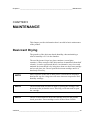
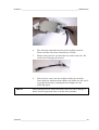
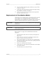
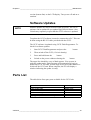
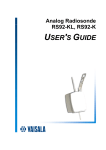
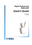
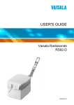
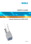
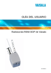
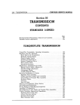
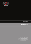
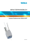
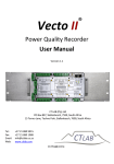
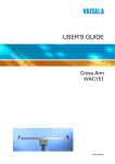
1
Ground Check Set
GC25
USER'S GUIDE
M210329EN-C
April 2005
PUBLISHED BY
Vaisala Oyj
P.O. Box 26
FIN-00421 Helsinki
Finland
Phone (int.): +358 9 8949 1
Fax:
+358 9 8949 2227
Visit our Internet pages at http://www.vaisala.com/
© Vaisala 2005
No part of this manual may be reproduced in any form or by any means,
electronic or mechanical (including photocopying), nor may its contents be
communicated to a third party without prior written permission of the copyright
holder.
The contents are subject to change without prior notice.
Please observe that this manual does not create any legally binding obligations for
Vaisala towards the customer or end user. All legally binding commitments and
agreements are included exclusively in the applicable supply contract or
Conditions of Sale.
________________________________________________________________________________
Table of Contents
CHAPTER 1
GENERAL INFORMATION............................................................................ 3
About This Manual ................................................................... 3
Contents of This Manual ....................................................... 3
Related Manuals ................................................................... 4
Safety......................................................................................... 4
General Safety Considerations ............................................. 4
Product Related Safety Precautions ..................................... 4
Warranty.................................................................................... 5
CHAPTER 2
PRODUCT OVERVIEW.................................................................................. 7
Introduction to GC25 Ground Check Unit.............................. 7
Operation Modes................................................................... 8
Ground Check Phases .......................................................... 9
Reconditioning ................................................................. 9
Setting the Frequency...................................................... 9
Setting the Timer (Killer) ................................................ 10
Conducting a Ground Check.......................................... 10
CHAPTER 3
INSTALLATION............................................................................................ 11
Getting Started ....................................................................... 11
Connections ........................................................................ 11
Stand-Alone Mode ......................................................... 11
Network Mode ................................................................ 11
Desiccant............................................................................. 12
Filling the Chamber with Desiccant..................................... 12
CHAPTER 4
OPERATION................................................................................................. 15
Operating Instructions........................................................... 15
User Interface...................................................................... 16
GC25 Connections.............................................................. 16
Radiosonde Placement ....................................................... 17
Radiosonde Preparation ..................................................... 18
Reconditioning ............................................................... 19
Frequency Setting .......................................................... 19
Timer Setting.................................................................. 20
Ground Check ................................................................ 20
CHAPTER 5
MAINTENANCE ........................................................................................... 23
VAISALA ________________________________________________________________________ 1
User's Guide ______________________________________________________________________
Desiccant Drying ....................................................................23
Calibration of Temperature Reference .................................24
Replacement of Temperature Reference Unit .....................24
Replacement of Ventilation Motor ........................................31
Replacement of Spare Sonde Cable.....................................32
Software Version and Calibration Information ....................32
Software Updates ................................................................33
Parts List .................................................................................33
PCB Connections ...................................................................34
CHAPTER 6
TROUBLESHOOTING..................................................................................35
Common Problems.................................................................35
Getting Help ............................................................................36
Return Instructions ................................................................37
CHAPTER 7
TECHNICAL DATA ......................................................................................39
Specifications .........................................................................39
List of Figures
Figure 1
Figure 2
Figure 3
Figure 4
Figure 5
Figure 6
Figure 7
Figure 8
Figure 9
Figure 10
Figure 11
Figure 12
Figure 13
Figure 14
Figure 15
Figure 16
GC25 Ground Check Set............................................................8
Open Desiccant Cartridge ........................................................13
GC25 Cable Connections.........................................................16
RS92 Digital Radiosonde in GC25 Ground Check Set ............18
Unscrew Back Plate .................................................................25
Remove Back Plate ..................................................................26
Unlock the Sensor Chord .........................................................26
Remove Chamber Screws........................................................27
Remove Fan Wire.....................................................................27
Remove Chamber Screws........................................................28
Remove Sensor from Chamber................................................29
New Sensor Chord with Protective Cap ...................................29
Press Sensor Gently into Place................................................30
Secure Ground Wire and Chamber Screws .............................30
Board Connections ...................................................................34
Correct Position for Chamber Sensors.....................................36
List of Tables
Table 1
Table 2
Table 3
Table 4
Operation Mode Compatibility for GC25 ....................................9
Available Spare Parts ...............................................................33
Some Common Problems and their Remedies ........................35
GC25 Ground Check Set Specifications ..................................39
2 ___________________________________________________________________ M210329EN-C
Chapter 1 ________________________________________________________ General Information
CHAPTER 1
GENERAL INFORMATION
About This Manual
This manual provides information for installing, operating, and
maintaining the GC25 Ground Check Set.
Contents of This Manual
This manual consists of the following chapters:
- Chapter 1, General Information, provides important safety, revision
history, and warranty information for the product.
- Chapter 2, Product Overview, introduces the GC25 Ground Check
Set features, advantages, and operation principle.
- Chapter 3, Installation, provides you with information that is
intended to help you install this product.
- Chapter 4, Operation, contains information that is needed to
operate this product.
- Chapter 5, Maintenance, provides information that is needed in
basic maintenance of the product.
- Chapter 6, Troubleshooting, describes common problems, their
probable causes and remedies, and contact information.
- Chapter 7, Technical Data, provides the technical data of the GC25
Ground Check Set.
VAISALA ________________________________________________________________________ 3
User's Guide ______________________________________________________________________
Related Manuals
Please refer to your radiosonde and ground equipment documentation
for more detailed information on the individual components and
software used with the Ground Check Set GC25.
Safety
General Safety Considerations
Throughout the manual, important safety considerations are
highlighted as follows:
WARNING
Warning alerts you to a serious hazard. If you do not read and follow
instructions very carefully at this point, there is a risk of injury or
even death.
CAUTION
Caution warns you of a potential hazard. If you do not read and
follow instructions carefully at this point, the product could be
damaged or important data could be lost.
NOTE
Note highlights important information on using the product.
Product Related Safety Precautions
The GC25 Ground Check Set delivered to you has been tested for
safety and approved as shipped from the factory. Note the following
precautions:
WARNING
Ground the product, and verify outdoor installation grounding
periodically to minimize shock hazard.
4 ___________________________________________________________________ M210329EN-C
Chapter 1 ________________________________________________________ General Information
CAUTION
Do not modify the unit. Improper modification can damage the
product or lead to malfunction.
Warranty
For certain products Vaisala normally gives a limited one year
warranty. Please observe that any such warranty may not be valid in
case of damage due to normal wear and tear, exceptional operating
conditions, negligent handling or installation, or unauthorized
modifications. Please see the applicable supply contract or conditions
of sale for details of the warranty for each product.
VAISALA ________________________________________________________________________ 5
User's Guide ______________________________________________________________________
This page intentionally left blank.
6 ___________________________________________________________________ M210329EN-C
Chapter 2 __________________________________________________________ Product Overview
CHAPTER 2
PRODUCT OVERVIEW
This chapter introduces the GC25 Ground Check Set features,
advantages, and operation principle.
Introduction to GC25 Ground Check Unit
The GC25 Ground Check Set is used to check the functioning of the
radiosonde and the sensor accuracy, as well as set the frequency of the
radiosonde. The GC25 is designed to be used with RS92 Digital and
Analog radiosondes.
The GC25 Ground Check Set includes desiccant for 0% RH humidity
reference. A glass jar with desiccant is also provided.
For optimum performance, the GC25 must be properly calibrated and
the calibration must be valid. The desiccant must also be dry. This will
ensure that the unit will give accurate and reliable readings.
VAISALA ________________________________________________________________________ 7
User's Guide ______________________________________________________________________
0212-254
Figure 1
GC25 Ground Check Set
The following numbers refer to Figure 1 above:
1
2
3
4
5
=
=
=
=
=
Chamber
Display
Buttons
Chamber clasp
Radiosonde tray
The GC25 has a power supply and communication connector for the
radiosonde. The GC25 unit is equipped with a display and buttons
used to control the radiosonde.
Operation Modes
GC25 can be operated in two modes: Stand-alone and Network mode.
In Network mode GC25 is connected to DigiCORA via cable and is
operated with the help of DigiCORA Sounding Software.
In Stand-alone mode GC25 is operated using the interface buttons on
the GC25 unit.
8 ___________________________________________________________________ M210329EN-C
Chapter 2 __________________________________________________________ Product Overview
If you are using a DigiCORA sounding system which has a software
supporting GC25 communication, the GC25 can be used in Standalone or Network mode. Other systems and older software versions
can only be used in Stand-alone mode. See Table 1 below for details.
Table 1
Operation Mode Compatibility for GC25
DigiCORA Sounding System
MW1x
MW21 software version < 3.12
MW21, MW31 software version >= 3.12
GC25 Operation Modes
Stand Alone
Stand Alone
Stand Alone or Network
Ground Check Phases
A ground check performed with the GC25 Ground Check Set is used
to fine-tune the measurements of meteorological parameters with the
RS92 Radiosonde before sounding. The ground check is carried out in
the following phases.
Reconditioning
To get optimum performance from the RS92 humidity sensors, the
ground check includes a phase for removing possible sensor
contamination. If any contamination has occurred before sonde
launch, for example in storage, this can be removed by sensor
reconditioning.
Contamination of the humidity sensor causes dry bias to humidity
measurement. Contaminating molecules occupy water-binding sites
and the effect may vary between zero to a few percent of relative
humidity, indicating readings that are too low. In the preparation
phase, the radiosonde is attached to the Ground Check set and
reconditioning power is connected to the humidity sensors for 3
minutes. Depending on the ground equipment in use, either the GC25
unit or ground equipment will ask you to conduct the reconditioning.
Setting the Frequency
In this phase, the RS92 Digital Radiosonde transmitter can be tuned
and set to a specific frequency.
VAISALA ________________________________________________________________________ 9
User's Guide ______________________________________________________________________
NOTE
RS92-K and RS92-KL Analog Radiosondes frequencies are tuned
differently to Digital Radiosondes. Refer to the RS92-K and RS92KL user manual for frequency setting information.
Setting the Timer (Killer)
In this phase, the timer can be set to shut off the radiosonde's
transmitter at a pre-selected time from launch.
Conducting a Ground Check
When the GC25 unit is in the actual ground check phase, the
radiosonde sensors are compared to references. The temperature
readings are displayed on the GC25 display. The chamber unit of the
GC25 contains the desiccant, drying agent, for 0 % humidity
reference. For pressure reading, a separate reference is needed. The
user gives the reference values to the ground equipment, which
compares them to those given by the radiosonde and makes the
necessary corrections. If used in Network mode, this is done
automatically via cable, not including pressure reference values. Read
pressure values from a reliable reference.
We recommend corrections only to be done with properly maintained
and calibrated units. Otherwise it is recommended to not conduct GCcorrections.
10 __________________________________________________________________ M210329EN-C
Chapter 3 _______________________________________________________________ Installation
CHAPTER 3
INSTALLATION
This chapter provides you with information that is intended to help
you install this product.
Getting Started
Connections
Stand-Alone Mode
When setting up the GC25 as a stand-alone ground check set, connect
the power supply connector to the connector marked POWER. Then
connect the Power Supply cable.
Press power and the display should read Connect Cable to Sonde. The
GC25 is now ready for use.
Network Mode
Connect the power supply connector to the connector marked
POWER. Then connect the Power Supply cable.
To use the GC25 with DigiCORA system in network mode, connect
the direct RS-232 cable to the slanted serial connector (on the back of
the GC25 unit) and the PC's serial port. Secure the cable with screws.
This cable is delivered with the GC25 Set.
Press power and the display should read Connect Cable to Sonde. The
GC25 is now ready for use.
VAISALA _______________________________________________________________________ 11
User's Guide ______________________________________________________________________
Desiccant
With first installation of the GC25 unit, please follow the Filling the
Chamber with Desiccant step list below carefully.
NOTE
As the desiccant beads require drying, it is convenient to use more
than one desiccant cartridge with the GC25 unit. With several
cartridges, they can be used in rotation. This way there is no need to
open and refill the cartridge with desiccant beads for drying purposes.
Extra cartridges can be ordered from Vaisala.
Filling the Chamber with Desiccant
During first installation:
1.
Pull out the desiccant cartridge from the side of the chamber.
For details refer to Figure 1 on page 8.
2.
Hold the base firmly and open the top of the desiccant cartridge.
Turn the screws to release the metal top. See Figure 2 on page
13 for details.
12 __________________________________________________________________ M210329EN-C
Chapter 3 _______________________________________________________________ Installation
0212-263
Figure 2
NOTE
NOTE
Open Desiccant Cartridge
Be careful not to deform or damage the metal netting. Always hold
the cartridge by the metal base.
3.
Fill the metal net enclosure with desiccant beads.
4.
Place the top of the desiccant cartridge into place.
5.
Close the screws to secure the metal top into place.
6.
Place the desiccant cartridge back into the side of the chamber.
Always make sure the chamber cover of the GC25 Ground Check set
is properly closed.
VAISALA _______________________________________________________________________ 13
User's Guide ______________________________________________________________________
This page intentionally left blank.
14 __________________________________________________________________ M210329EN-C
Chapter 4 ________________________________________________________________ Operation
CHAPTER 4
OPERATION
This chapter contains information that is needed to operate this
product.
Operating Instructions
NOTE
When installed in Network Mode, the GC25 and DigiCORA
communicate automatically via cable. In this case, do not press the
buttons on the GC25 unit (other than ON/OFF) as this will disrupt
communications. Pressure reference values need to be read from a
separate reliable pressure reference source.
The GC25 Ground Check set is used to prepare the radiosonde for
optimal performance. This is done in four stages:
- Reconditioning, the radiosonde is prepared for ground check.
- Frequency tuning, the frequency is set.
- Timer setting, the radiosonde transmitter operation time is set.
- Ground check, the transmitter is on, comparing PTU values.
NOTE
To conduct successful ground check corrections, you must have
reliable, calibrated, and valid PTU references available. If no such
references are available, it is recommended to leave out the ground
check corrections phase.
VAISALA _______________________________________________________________________ 15
User's Guide ______________________________________________________________________
User Interface
NOTE
Note that when the GC25 is installed in Network Mode, the GC25
and DigiCORA communicate automatically via cable. In this case, do
not press the buttons on the GC25 unit (other than ON/OFF) as this
will disrupt communications.
The GC25 Ground Check set has an LCD display and five buttons.
Below is a description of each button and its function.
Back
Left Arrow
Right Arrow
Select
Power
=
=
=
=
=
Use this button to return to the previous menu.
Use this button to scroll left.
Use this button to scroll right.
Use this button to make your selection.
Switches power on and off to the GC25 unit.
GC25 Connections
In the following figure, the GC25 cable connections are shown in
detail. The serial cable is connected to the PC, enabling Network
mode. Refer to DigiCORA documentation for connection to PC.
1
2
0504-002
Figure 3
GC25 Cable Connections
The following numbers refer to Figure 3 above:
1
2
=
=
Serial cable connection to PC for Network mode
Power cable connection
16 __________________________________________________________________ M210329EN-C
Chapter 4 ________________________________________________________________ Operation
Radiosonde Placement
The proper way to place the radiosonde into the GC25 Ground Check
Set is described below.
CAUTION
1.
Push back the clasp of the chamber and open the cover.
2.
Place the radiosonde carefully (with the dummy battery cover)
onto its tray, gently setting the sensor boom into the chamber.
Rough handling of the chamber cover can damage the sensor boom.
3.
CAUTION
Gently close the chamber cover and carefully fasten the clasp.
Be careful not to touch or hit the RS92 sensors on the sensor boom,
as the sensors are fragile.
4.
With the radiosonde in place, lift the flap at the back of the
radiosonde and carefully connect the radiosonde connector to
the radiosonde. Be careful not to move the radiosonde, so as to
not damage the sensor boom in the chamber. Figure 4 on page
18 illustrates the correct placement of the radiosonde into the
GC25 unit.
CAUTION
Make sure the UP text on the radiosonde connector plug is facing up.
CAUTION
Make sure the radiosonde connector is connected to the radiosonde
with the UP text facing up, without turning the flatwire.
VAISALA _______________________________________________________________________ 17
User's Guide ______________________________________________________________________
0212-244
Figure 4
CAUTION
RS92 Digital Radiosonde in GC25 Ground Check
Set
Be careful not to touch the RS92 sensors on the sensor boom. The
temperature sensor is very fragile.
Radiosonde Preparation
Use the display and buttons to conduct the ground check. However, if
the GC25 is connected to DigiCORA via cable do not use the buttons
on the GC25 unit.
The functioning of the display and buttons are explained in section
User Interface on page 16. Switch on the GC25 unit by pressing the
power button. When the GC25 is on, the green LED light is lit. The
following text will appear:
Connect Cable to Sonde.
The ground check will automatically begin when an RS92 radiosonde
has been connected to it.
18 __________________________________________________________________ M210329EN-C
Chapter 4 ________________________________________________________________ Operation
Reconditioning
NOTE
The following steps are only required if you are using the GC25 in
stand-alone mode. Otherwise, DigiCORA software will complete the
following steps automatically.
1.
The GC25 unit will ask if you wish to recondition. The
following text will appear:
Recond. U-sensor?
YES
Reply YES or NO using the arrow buttons and press Select to
confirm your choice. If you choose to recondition, this will take
approximately three minutes.
Reconditiong...
Remaining: 1:41
During reconditioning the Remaining time is displayed. Note
that, if the time is not shown, or an error message is given (for
example, Communication Error), the radiosonde connection
needs to be checked; disconnect and then reconnect the
radiosonde and restart the ground check.
NOTE
The following steps are only required if you are using the GC25 in
stand-alone mode. Otherwise, DigiCORA software will complete the
following steps automatically.
Frequency Setting
NOTE
When using RS92-K and RS92-KL Analog Radiosondes, the GC25
unit will automatically skip Frequency Setting, and go to Ground
Check stage on page 20.
NOTE
RS92-K and RS92-KL Analog Radiosondes frequencies are tuned
differently to Digital Radiosondes. Refer to the RS92-K and RS92KL user manual for frequency setting information.
2.
Next the GC25 unit will ask you to set the frequency, the display
will show the radiosonde factory default value. The following
text will appear:
VAISALA _______________________________________________________________________ 19
User's Guide ______________________________________________________________________
Frequency: 405.35 MHz
Tune freq.? NO
If you do not want to tune the frequency, press Select. If you
wish to tune the frequency, use the arrow key to select YES and
press Select. Then use the arrow buttons to scroll for the desired
frequency and press Select to confirm your choice.
Note that, if nothing is displayed during frequency setting, or an
error message is given (for example, Communication Error), the
radiosonde connection needs to be checked; disconnect and then
reconnect the radiosonde and restart the ground check.
3.
Next you will enter the Timer Set mode, press Select to
continue.
Timer Setting
NOTE
The following steps are only required if you are using the GC25 in
stand-alone mode. Otherwise, DigiCORA software will complete the
following steps automatically.
4.
The timer is used to shut off the transmitter at pre-selected time
from release (launch). The following text will appear on the
display:
Timer: disabled
Set Timer? NO
Select either YES or NO using the scroll buttons and press
Select to confirm your selection. Then hold down the arrow
buttons to scroll the timer either UP or DOWN. Note that 15
minutes is the minimum selectable time. When the value is
scrolled under15 minutes, the timer will be disabled. Press
Select to confirm your choice. To re-set, press Back. Then
select YES again to re-set a new time, or to disable the timer.
5.
When the timer has been set, you will enter ground check mode.
Ground Check
NOTE
The following steps are only required if you are using the GC25 in
stand-alone mode. Otherwise, DigiCORA software will complete the
following steps automatically.
20 __________________________________________________________________ M210329EN-C
Chapter 4 ________________________________________________________________ Operation
At this stage, please wait until GC25 informs you the conditions have
been stabilized. This can take 2 minutes after reconditioning has
ended.
6.
The radiosonde transmitter is enabled.
7.
Enter temperature value into the ground equipment, when the
ground equipment asks for them. The temperature is shown on
the GC25 unit's display as follows:
Reference:
T = 23.45 °C
8.
NOTE
Humidity, at this stage, is 0%. Make sure that the desiccant
beads are completely dry. Enter 0% for humidity into the ground
equipment. This value is achieved after the chamber has been
stabilized.
If humidity levels begin to rise, and changing the desiccant beads has
not helped to correct this, check to see if the fan is working. There
should be an audible humming noise.
9.
Once the PTU values have been given to the ground equipment,
the ground check is complete.
Carefully remove the radiosonde (do not damage the sensors) from the
GC25 unit and prepare the radiosonde for launch.
Now the radiosonde can be prepared for launch. For details, refer to
the appropriate RS92 radiosonde manual. See Related Manuals on
page 4 for further information.
VAISALA _______________________________________________________________________ 21
User's Guide ______________________________________________________________________
This page intentionally left blank.
22 __________________________________________________________________ M210329EN-C
Chapter 5 ______________________________________________________________ Maintenance
CHAPTER 5
MAINTENANCE
This chapter provides information that is needed in basic maintenance
of the product.
Desiccant Drying
The granules of the desiccant absorb humidity, thus maintaining a
relative humidity of 0 % in the chamber.
The used desiccant is kept in a glass container (second glass
container). When enough of the desiccant has accumulated (about half
a bottle), it can be regenerated (dried). An alternative way to use and
maintain desiccant beads is by using more than one desiccant cartridge
and several glass jars. Do not open the desiccant cartridge until it is
absolutely necessary.
NOTE
Direct exposure to the sun or other source of heat such as keeping a
hand on the cup for a long time will cause incorrect temperature and
humidity readings.
NOTE
The desiccant beads can also be dried by placing the cartridge with
desiccant in the jar into the oven. This way you do not need to open
the cartridge.
NOTE
The use of more than one desiccant cartridge will ease the ground
check procedure. Extra cartridges can be ordered from Vaisala.
VAISALA _______________________________________________________________________ 23
User's Guide ______________________________________________________________________
Proceed in the following way:
1.
Put the glass container with the used drying agent or cartridge
into an oven. Remove the container cover.
2.
Raise the oven temperature to +250 °C (or more) and maintain
this temperature for three hours.
3.
Let the oven cool down.
4.
Remove the container from the oven when the temperature is
below +70 °C and close the container cover.
5.
The drying agent is now ready for use again.
The desiccant beads need to be changed at certain time intervals (for
example regularly once a month), depending on the humidity levels in
the area and the number of soundings conducted, however latest when
humidity reading is 2 % RH.
Calibration of Temperature Reference
The recommended calibration interval for temperature reference is one
year. Please contact Vaisala ([email protected]) to order
temperature reference calibration.
In practice, calibration will be done by replacing your current
temperature reference unit with a new one. Upon receiving the new
temperature reference unit, install it as explained in section
Replacement of Temperature Reference Unit below and return the old
unit to Vaisala.
The calibration date can be checked as explained in Software Version
and Calibration Information on page 32.
Replacement of Temperature Reference Unit
Detailed information on how to replace the temperature reference unit
is explained in below:
CAUTION
Disconnect power to the GC25 unit completely before replacing the
sensor unit.
24 __________________________________________________________________ M210329EN-C
Chapter 5 ______________________________________________________________ Maintenance
CAUTION
Always follow ESD protection guidelines when making adjustments
to the Ground Check Set.
Refer to Figure 15 on page 34 for a detailed board connections
illustration.
To replace the temperature reference unit, you will need a flathead
screwdriver and a 2.5-mm hex-key.
1.
With the GC25 unit switched off, turn the unit over and open the
bottom cover by removing the four large screws at each corner
using the flathead screwdriver. Remove the plate.
Figure 5
Unscrew Back Plate
VAISALA _______________________________________________________________________ 25
User's Guide ______________________________________________________________________
Figure 6
2.
Unclip and pull out the sensor chord from its connector by
pulling the hinges open to the sides as shown in the following
picture.
Figure 7
3.
Remove Back Plate
Unlock the Sensor Chord
Turn the unit around. Remove the two screws on the top of the
chamber using the 2.5-mm hex-key as shown in Figure 8 on
page 27.
26 __________________________________________________________________ M210329EN-C
Chapter 5 ______________________________________________________________ Maintenance
Figure 8
4.
Remove Chamber Screws
Turn the GC25 unit over. You can see the thick sensor chord
from which a small wire (the fan wire) is connected to the PCB
and a second ground wire, which is attached to one of the
chamber screws.
-
Figure 9
First, disconnect the black fan wire from the PCB. Indicated
with a white arrow in the following image.
Remove Fan Wire
VAISALA _______________________________________________________________________ 27
User's Guide ______________________________________________________________________
-
Then, unscrew the two silver screws which hold the chamber
in place. See the following image for details.
'
Figure 10
5.
NOTE
Remove Chamber Screws
Turn the unit around and carefully lift the chamber out of its
place. Set down the GC25 and carefully remove the sensor unit
from the chamber, see the following Note and refer to Figure 11
on page 29.
When removing the sensor unit, take care not to damage the sensors
against the sides or walls of the chamber.
28 __________________________________________________________________ M210329EN-C
Chapter 5 ______________________________________________________________ Maintenance
Figure 11
6.
The old sensor chord has now been successfully removed.
Please send the old sensor chord back to Vaisala.
7.
Remove the protective cap from the new sensor with care. Be
careful not to damage the sensors!
Figure 12
8.
NOTE
Remove Sensor from Chamber
New Sensor Chord with Protective Cap
Place the new sensor into the chamber firmly but carefully.
Once again pay attention to the rubber seal, make sure the seal is
set properly into place, making the hole airtight. See the
following figure.
When placing the new sensor into place, take care not to damage or
hit the sensors against the sides or walls of the chamber.
VAISALA _______________________________________________________________________ 29
User's Guide ______________________________________________________________________
Figure 13
9.
Press Sensor Gently into Place
Feed the cable of the new sensor unit through the hole of the
GC25 unit and set the chamber back into position.
-
First, put the two silver screws back into place, making sure
that the ground wire from the new sensor cable is connected
beneath the second screw.
Figure 14
Secure Ground Wire and Chamber Screws
- Connect the black fan wire to the printed circuit board (PCB).
NOTE
Make sure the black fan wire is reconnected properly so that the three
pins are secured into the cap.
30 __________________________________________________________________ M210329EN-C
Chapter 5 ______________________________________________________________ Maintenance
10.
Secure the chamber back into place with the two screws. Refer
to Figure 8 on page 27.
11.
Connect the sensor chord connector head to the clip by closing
the clip hinges. See Figure 7 on page 26.
12.
Finally close the bottom of the unit and secure the plate back
into place with the four screws.
Replacement of Ventilation Motor
To determine if the ventilation motor is functioning properly open the
GC25 chamber cover in ground check mode. If the motor is not
buzzing and air is not circulating, the ventilation motor will need to be
replaced. Follow the steps below to replace the ventilation motor.
CAUTION
Disconnect power to the GC25 unit completely before replacing the
chamber unit.
CAUTION
Always follow ESD protection guidelines when making adjustments
to the Ground Check Set.
Refer to Figure 15 on page 34 for a detailed board connections
illustration.
1.
Open the bottom of the of the GC25 unit by removing the two
large screws.
2.
Remove the motor connector by opening the connector clip
hinges of connector clip located on the left.
3.
Next, open the chamber cover and remove the ventilation plate.
4.
Gently lift the chamber motor from its place, pulling out the flat
wire from inside the unit.
5.
Put the new ventilation motor into place.
6.
Connect the wire to the connector clip and make sure the hinges
are properly fastened.
7.
Close the bottom cover of the GC25 unit.
VAISALA _______________________________________________________________________ 31
User's Guide ______________________________________________________________________
Replacement of Spare Sonde Cable
The radiosonde cable may need to be replaced when error messages
are frequent or the connector no longer connects to the sonde with
ease.
CAUTION
Disconnect power to the GC25 unit completely before replacing the
chamber unit.
CAUTION
Always follow ESD protection guidelines when making adjustments
to the Ground Check Set.
NOTE
1.
Open the bottom of the GC25 unit by removing the four large
screws.
2.
Disconnect the sonde cable (see Figure 15 on page 34 for
details) by opening the connector clip hinges of the connector
clip located on the left.
3.
Remove the rubber bushing from the old sonde cable.
4.
Attach the rubber bushing to the new sonde cable.
5.
Connect the new cable to the connector clip on the left. The
cable is marked Sonde cable in Figure 15 on page 34.
6.
With the clip secured in place, twist the wire slightly to ensure
that the UP text faces up.
Make sure the UP text on the new sonde cable is facing upward to
ensure correct connection to radiosonde.
Software Version and Calibration Information
With no radiosonde connected, and the GC25 power on, press the
right down arrow to view the calibration date on the LCD display. If a
year has passed since the date displayed, the calibration is no longer
valid. In this case refer to Calibration on page 24.
With no radiosonde connected, and the GC25 power on, press the left
down arrow to view the calibration number (top line) and software
32 __________________________________________________________________ M210329EN-C
Chapter 5 ______________________________________________________________ Maintenance
version (bottom line) on the LCD display. Turn power off and on to
continue.
Software Updates
NOTE
Software updates are only to be done when necessary. The GC25
software can be updated as you update DigiCORA software. Also,
Vaisala may separately request that the GC25 software is updated.
To update the GC25 software it must be connected to a PC. This can
be done using the RS-232 cable provided with the GC25.
The GC25 software is updated using GC25 Flash Programmer. To
check for software updates:
1.
Start GC25 Flash Programmer and press the Update button.
2.
Then switch off the GC25 (if it isn't already).
3.
Press and hold down the Back button
4.
Switch on the power without releasing the Back button.
The upper line should be a row of dark squares. You are now in
software update mode. Flash Program will automatically begin to
update the GC25 via cable. At this stage do not press other buttons or
switch off the GC25 unit. When complete, the PC will display a
window indicating the update is ready.
Parts List
The table below lists spare parts available for the GC25 unit.
Table 2
Available Spare Parts
Spare Part
Ventilation motor fan
Spare sonde cable
Calibrated PT-100 sensor unit
Desiccant cartridge
Desiccant beads
Empty glass jar for desiccant/cartridge
Order Code
212196
DRW214987
DRW215049
DRW214686
4161GC
4162GC
VAISALA _______________________________________________________________________ 33
User's Guide ______________________________________________________________________
NOTE
When ordering a new desiccant cartridge, it is recommended to also
order the empty glass jar for drying purposes.
PCB Connections
Figure 15 below provides a detailed illustration of the board
connections inside the GC25 unit.
1
2
6
5
4
3
7
Figure 15
Board Connections
The following numbers refer to Figure 15 above:
1.
2.
3.
4.
5.
6.
7.
Fan connector
Ground equipment cable (connect to PC for Network mode
operation, not needed for Stand-alone operation.)
Optional AUTOSONDE -reset
Power
Printed circuit board (PCB)
PT sensor unit (Part no. DRW215049)
Sonde cable (Part no. DRW214987)
34 __________________________________________________________________ M210329EN-C
Chapter 6 ___________________________________________________________ Troubleshooting
CHAPTER 6
TROUBLESHOOTING
This chapter describes common problems, their probable causes and
remedies, and contact information.
Common Problems
Table 3
Problem
Frequency is not shown or
displayed
Remaining time is not shown
for ground check
Display reads Communication
Error
LCD reads "Check Desiccant!
Press Select"
LCD reads "Check Temp
Sensor"
Humidity levels begin to rise
Temperature unit error
Invalid calibration info
Some Common Problems and their Remedies
Probable Cause
Radiosonde connection
cable is loose
Radiosonde connection
cable is loose
Radiosonde connection
cable is loose
Desiccant beads are wet
The sensor is bent
The fan is not working
PT-sensor unit
malfunctioning or loose
There is a discrepancy
between calibration values,
failed temperature
calculations
Remedy
Check cable, reconnect if necessary
Check cable, reconnect if necessary
Check cable, reconnect if necessary
Recondition desiccant beads.
See Figure 16 on page 36 for correct
positioning of chamber sensors.
Check if the fan is spinning, there
should be an audible humming noise.
Check PT-sensor connection
Check PT-sensor cable. Contact
HelpDesk.
VAISALA _______________________________________________________________________ 35
User's Guide ______________________________________________________________________
Figure 16
Correct Position for Chamber Sensors
Getting Help
For technical questions or for comments on the manuals, contact the
Vaisala technical support:
E-mail
[email protected]
Telephone
+358 9 8949 2789
Fax
+358 9 8949 2790
36 __________________________________________________________________ M210329EN-C
Chapter 6 ___________________________________________________________ Troubleshooting
Return Instructions
If the product needs repair, please follow the instructions below to
speed up the process and avoid extra costs.
1.
Read the warranty information.
2.
Write a Problem Report with the name and contact information
of a technically competent person who can provide further
information on the problem.
3.
On the Problem Report, please explain:
- What failed (what worked / did not work)?
- Where did it fail (location and environment)?
- When did it fail (date, immediately / after a while /
periodically / randomly)?
- How many failed (only one defect / other same or similar
defects / several failures in one unit)?
- What was connected to the product and to which connectors?
- Input power source type, voltage and list of other items
(lighting, heaters, motors etc.) that were connected to the
same power output.
- What was done when the failure was noticed?
4.
Include a detailed return address with your preferred shipping
method on the Problem Report.
5.
Pack the faulty product using an ESD protection bag of good
quality with proper cushioning material in a strong box of
adequate size. Please include the Problem Report in the same
box.
6.
Send the box to:
Vaisala Oyj
Contact person / Division
Vanha Nurmijärventie 21
FIN-01670 Vantaa
Finland
VAISALA _______________________________________________________________________ 37
User's Guide ______________________________________________________________________
This page intentionally left blank.
38 __________________________________________________________________ M210329EN-C
Chapter 7 ____________________________________________________________ Technical Data
CHAPTER 7
TECHNICAL DATA
This chapter provides the technical data of the GC25 Ground Check
Set.
Specifications
Table 4
GC25 Ground Check Set Specifications
Property
Operating conditions
Humidity
Temperature
Temperature sensor
- Uncertainty1)
- Resolution
Storage temperature
Dimensions
Weight
Power supply
Input
Output
Power consumption
Connectors
Drying agent
Description / Value
0 ... 85% RH
+5 ... +45 °C
Pt-100 IEC 751
0.1 °C
0.01 °C
-40 … +70 °C
25 cm (w) x 18 cm (d) x 9 cm (h) 2)
2.1 kg
100 - 240V (47 - 63 MHz)
16V DC
6W
Ground equipment
External pressure reference
Power supply
Molecular sieve pellets, regenerable
1)
One-year calibration intervals ensure the validity of uncertainty values (+5 to +45 °C).
2)
Dimensions: weight x depth x height
VAISALA _______________________________________________________________________ 39