1
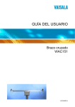
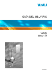
Analog Wind Transmitter
WAT12
USER'S GUIDE
M210309EN-A
June 2002
PUBLISHED BY
Vaisala Oyj
P.O. Box 26
FIN-00421 Helsinki
Finland
Phone (int.):+358 9 8949 1
Fax:
+358 9 8949 2227
Visit our Internet pages at http://www.vaisala.com/
© Vaisala 2002
No part of this manual may be reproduced in any form or by any
means, electronic or mechanical (including photocopying), nor may its
contents be communicated to a third party without prior written
permission of the copyright holder.
The contents are subject to change without prior notice.
Please observe that this manual does not create any legally binding
obligations for Vaisala towards the customer or end user. All legally
binding commitments and agreements are included exclusively in the
applicable supply contract or Conditions of Sale.
___________________________________________________________________
Table of Contents
CHAPTER 1
GENERAL INFORMATION .......................................................5
About This Manual..................................................5
Contents of This Manual.......................................5
Version Information...............................................6
Related Manuals...................................................6
Safety .......................................................................6
General Safety Considerations.............................6
Product Related Safety Precautions .....................7
ESD Protection .....................................................7
Regulatory Compliances........................................8
Warranty ..................................................................8
CHAPTER 2
PRODUCT OVERVIEW.............................................................9
Introduction to WAT12 Analog Wind
Transmitter ..............................................................9
CHAPTER 3
INSTALLATION ......................................................................11
Selecting Location ................................................11
Installation Procedure ..........................................13
Jumper Settings..................................................14
Connections........................................................16
Sensor Wiring.................................................18
Signal Output..................................................19
Powering ........................................................21
Optional Heating Power..................................22
Wiring Examples ............................................23
Mounting the Thermostat Switch ........................26
Mounting.............................................................27
Mounting WAT12 to the Top of a Pole Mast...27
Mounting Wind Sensors to WAT12 ................28
Alignment............................................................29
Verification..........................................................29
VAISALA___________________________________________________________1
User's Guide ________________________________________________________
CHAPTER 4
MAINTENANCE...................................................................... 31
Periodic Maintenance .......................................... 31
Visual Checking ................................................. 31
Testing Proper Operation................................... 31
Replacing Consumables...................................... 33
Parts List for Consumables ................................ 33
CHAPTER 5
TROUBLESHOOTING............................................................ 35
Common Problems .............................................. 35
Error Messages .................................................... 35
Getting Help .......................................................... 36
Return Instructions .............................................. 37
CHAPTER 6
TECHNICAL DATA................................................................. 39
Specifications ....................................................... 39
List of Figures
Figure 1
Figure 2
Figure 3
Figure 4
Figure 5
Figure 6
Figure 7
Figure 8
Figure 9
Figure 10
Figure 11
Figure 12
Figure 13
Figure 14
Figure 15
WAT12 Analog Wind Transmitter ........................... 10
Recommended Mast Location in Open Area.......... 11
Recommended Mast Length on Top of
a Building ............................................................... 12
Location of the Jumpers ......................................... 14
Jumpers for the Setting: 4 ... 20 mA, 0° ... 360°,
0 ... 51.2 m/s........................................................... 15
Jumpers for the Setting: 1 ... 5 mA, 0° ... 360°,
0 ... 76.8 m/s........................................................... 16
Jumpers for the Setting: 0 ... 10 mA, 0° ... 540°,
0 ... 51.2 m/s........................................................... 16
Cable Shield Bent over the Plastic Sleeve
and O-ring .............................................................. 17
I/O Connectors ....................................................... 17
Wiring of the Sensors ............................................. 18
Typical System with 24 VDC Power Supply
and 5 mA Signal Currents ...................................... 19
Wiring for High Noise Environment ........................ 20
Long Distance Wiring ............................................. 20
Long Distance Wiring with Four Wires ................... 21
Default Heating Power Connection with both
Sensors .................................................................. 22
2 ______________________________________________________M210309EN-A
___________________________________________________________________
Figure 16 Basic Wiring with WAA151 and WAV151
Sensors...................................................................23
Figure 17 Wiring with WHP151 Mains Power Supply .............24
Figure 18 Wiring with WHP25 Mains Power Supply
and the 252 Series Wind Sensors ..........................25
Figure 19 Mounting the Thermostat Switch inside
the WAT12 Junction Box ........................................26
Figure 20 Standard Connection for Thermostat Switch ..........27
Figure 21 Mounting WAT12 to the Top of a Pole Mast ...........27
Figure 22 Installation of the Wind Sensors WAA151 and
WAV151 to WAT12.................................................28
List of Tables
Table 1
Table 2
Table 3
Table 4
Table 5
Manual Revisions......................................................6
Related Manuals .......................................................6
Jumper Settings for the 1 to 5 mA Current Loop.....15
I/O Connectors........................................................18
Power Line Resistance with an 24 VDC Power
Supply.....................................................................21
Table 6 Jumper Selectable Reference Sources
for Testing...............................................................32
Table 7 Output Values for the Jumpers in the Test Mode....32
Table 8 Available Spare Parts .............................................33
Table 9 Some Common Problems and their Remedies.......35
Table 10 WAT12 Analog Wind Transmitter Specifications ....39
VAISALA___________________________________________________________3
User's Guide ________________________________________________________
This page intentionally left blank.
4 ______________________________________________________M210309EN-A
Chapter 1 ___________________________________________ General Information
CHAPTER 1
GENERAL INFORMATION
About This Manual
This manual provides information for installing and
maintaining WAT12 Analog Wind Transmitter.
Contents of This Manual
This manual consists of the following chapters:
- Chapter 1, General Information, provides important
safety, revision history, and warranty information for the
product.
- Chapter 2, Product Overview, introduces WAT12 Analog
Wind Transmitter features.
- Chapter 3, Installation, provides you with information
that is intended to help you install this product.
- Chapter 4, Maintenance, provides information that is
needed in basic maintenance of WAT12 Analog Wind
Transmitter.
- Chapter 5, Troubleshooting, describes common problems,
their probable causes and remedies, and provides contact
information.
- Chapter 6, Technical Data, provides technical data of
WAT12 Analog Wind Transmitter.
VAISALA___________________________________________________________5
User's Guide ________________________________________________________
Version Information
Table 1
Manual Revisions
Manual Code
T649en-1.1
M210309EN-A
Description
WAT12 Analog Wind Transmitter Technical Reference.
This manual, the first version of WAT12
Analog Wind Transmitter User's Guide.
Supersedes the above mentioned
Technical Reference.
Related Manuals
Table 2
Related Manuals
Manual Code
M210293en
M210294en
Manual Name
WAA151 Anemometer - User's Guide
WAV151 Wind Vane - User's Guide
Safety
General Safety Considerations
Throughout the manual, important safety considerations are
highlighted as follows:
WARNING
Warning alerts you to a serious hazard. If you do not read
and follow instructions very carefully at this point, there is
a risk of injury or even death.
CAUTION
Caution warns you of a potential hazard. If you do not read
and follow instructions carefully at this point, the product
could be damaged or important data could be lost.
6 ______________________________________________________M210309EN-A
Chapter 1 ___________________________________________ General Information
NOTE
Note highlights important information on using the product.
Product Related Safety
Precautions
WAT12 Analog Wind Transmitter delivered to you has
been tested for safety and approved as shipped from the
factory. Note the following precautions:
WARNING
Ground the product, and verify the grounding of the
outdoor installation periodically to minimize shock hazard.
CAUTION
Do not modify the unit. Improper modification can damage
the product or lead to malfunction.
ESD Protection
Electrostatic Discharge (ESD) can cause immediate or latent
damage to electronic circuits. Vaisala products are
adequately protected against ESD for their intended use.
However, it is possible to damage the product by delivering
electrostatic discharges when touching, removing, or
inserting any objects inside the equipment housing.
To make sure you are not delivering high static voltages
yourself:
- Handle ESD sensitive components on a properly
grounded and protected ESD workbench. When this is
not possible, ground yourself to the equipment chassis
VAISALA___________________________________________________________7
User's Guide ________________________________________________________
before touching the boards. Ground yourself with a wrist
strap and a resistive connection cord. When neither of the
above is possible, touch a conductive part of the
equipment chassis with your other hand before touching
the boards.
- Always hold the boards by the edges and avoid touching
the component contacts.
Regulatory Compliances
WAT12 Analog Wind Transmitter is a CE compliant
product.
Warranty
For certain products Vaisala normally gives a limited one
year warranty. Please observe that any such warranty may
not be valid in case of damage due to normal wear and tear,
exceptional operating conditions, negligent handling or
installation, or unauthorized modifications. Please see the
applicable supply contract or conditions of sale for details of
the warranty for each product.
8 ______________________________________________________M210309EN-A
Chapter 2 ____________________________________________ Product Overview
CHAPTER 2
PRODUCT OVERVIEW
This chapter introduces WAT12 Analog Wind Transmitter
features.
Introduction to WAT12 Analog Wind
Transmitter
The WAT12 transmitter converts the digital data supplied
by the Vaisala 151 and 252 Series wind sensors, into two
industry standard analog current loops; one representing the
wind speed and the other the wind direction. The current
loops are suitable for connection to, for example, chart
recorders, analog or digital panel meters, analog inputs of
computers, or other instruments with an analog input
interface. The power to the sensors is also supplied through
the WAT12 transmitter. The transmitter accepts a wide
range of input power, from 12 to 28 VDC.
The WAT12 transmitter consists of a printed circuit board
unit in a junction box and a cross arm for mounting the wind
sensors, see Figure 1 on page 10. A 4-wire cable for the
wind speed and direction signals and power supply is
needed between the transmitter and the receiving end.
The loop current is user selectable. The loops are supplied
by high-side drivers with a return to the signal and power
ground; thus nearly any input type can be driven.
VAISALA___________________________________________________________9
User's Guide ________________________________________________________
The WAT12 transmitter provides the sensors with a
throughput for optional heating power. A thermostat switch
is available as an option to automatically connect the
heating power in temperatures below +4 °C.
0206-041
Figure 1
WAT12 Analog Wind Transmitter
The following numbers refer to Figure 1 above:
1
2
3
= Flange for mounting a Vaisala anemometer
= Junction box, containing the circuit board
= Flange for mounting a Vaisala wind vane
10 _____________________________________________________M210309EN-A
Chapter 3 __________________________________________________ Installation
CHAPTER 3
INSTALLATION
This chapter provides you with information that is intended
to help you install this product.
Selecting Location
Allow sufficient clearance for the wind sensors. Wind
sensors should not be located next to a building or any other
object that might affect the flow of air.
0204-040
Figure 2
Recommended Mast Location in Open Area
VAISALA__________________________________________________________11
User's Guide ________________________________________________________
In general, any object of height (h) will not remarkably
disturb wind measurement at a minimum distance of 10 × h.
There should be at least 150 m open area in all directions
from the mast. Refer to Figure 2 on page 11.
0204-041
Figure 3
Recommended Mast Length on Top of a
Building
The recommended minimum length (marked with the letter
h in Figure 3 above) for the mast that is installed on top of a
building is 1.5 times the height of the building (H). When
the diagonal (W) is less than the height (H), the minimum
length of the mast is 1.5 × W.
12 _____________________________________________________M210309EN-A
Chapter 3 __________________________________________________ Installation
Installation Procedure
For installation, follow the procedure below and refer to
corresponding sections for details.
1.
Remove the four screws holding the cover of the
WAT12 transmitter. Remove the cover.
2.
Select the current output span, as well as direction and
speed scaling according to the instructions in section
Jumper Settings on page 14. Some examples of
selecting scales and ranges are shown in Figure 5 on
page 15, Figure 6 on page 16, and Figure 7 on page 16.
3.
Enter the power and signal cables through the cable
glands(s). For better protection against RF interference,
ground the cable shield as shown in Figure 8 on page
17.
4.
Connect the wires to the X2 removable screw terminal
block according to Figure 11 on page 19, Figure 12 on
page 20, Figure 13 on page 20, or Figure 14 on page
21. Tighten the output cable gland(s).
5.
Carefully reattach the enclosure cover with the four
screws.
6.
Attach the unit on the top of a pole mast with the
mounting clamp as shown in Figure 21 on page 27.
7.
Mount the sensors onto the cross arm. Refer to Figure
22 on page 28 and the sensors' manuals.
8.
Align the cross arm as instructed in section Alignment
on page 29 before erecting the mast.
VAISALA__________________________________________________________13
User's Guide ________________________________________________________
Jumper Settings
The loop current can be selected with the on-board jumper
plugs. Several output ranges, such as 0 to 20 mA, 4 to
20 mA, 0 to 10 mA, 2 to 10 mA, 0 to 5 mA, and 1 to 5 mA,
are available as user configurable options, each with
factory-adjusted zero and span levels. The voltage-mode
signals are easily obtained by connecting a suitable resistor
across the readout device's terminals. Signal full scale
options are also available. For instance, a directional scale
of 540° (0-360-180°), which is convenient for analog panel
meters or chart recorders, can be chosen to prevent the
needle or pen from oscillating across the scale with
northerly winds.
0206-042
Figure 4
Location of the Jumpers
The following numbers refer to Figure 4 above.
1
2
3
4
5
=
=
=
=
=
X4: Test and operation
X5: Output zero
X7: Scaling together with X6
X8: Output span
X6: Scaling together with X7
14 _____________________________________________________M210309EN-A
Chapter 3 __________________________________________________ Installation
For example, you can set the wind speed output from 1 to
5 mA which corresponds to speed values from 0 to 51.2 m/s
and to direction values from 0 to 540 degrees. This range
does not change the scaling of 360 degrees corresponding to
one full turn, rather it allows to calculate the average
direction during northerly winds. These settings are carried
out by the jumpers of the WAT12 transmitter as described
in Table 3 below.
Table 3
Jumper
X4
X5
X6
X7
X7
X8
Jumper Settings for the 1 to 5 mA Current
Loop
J5 ON
J1 ON
J1 ON
J3 ON
J5 ON
J6 ON
ALL OFF
Description
Normal operation
1 / 2 / 4 mA for 51.2 m/s
0 ... 540°
0 ... 51.2 m/s
1 ... 5 mA
Some examples for selecting scales and ranges are shown in
Figure 5 below, Figure 6 on page 16, and Figure 7 on page
16.
0206-043
Figure 5
Jumpers for the Setting: 4 ... 20 mA,
0° ... 360°, 0 ... 51.2 m/s
VAISALA__________________________________________________________15
User's Guide ________________________________________________________
0206-044
Figure 6
Jumpers for the Setting: 1 ... 5 mA,
0° ... 360°, 0 ... 76.8 m/s
0206-045
Figure 7
Jumpers for the Setting: 0 ... 10 mA,
0° ... 540°, 0 ... 51.2 m/s
Connections
The WAT12 transmitter provides the line cable entry
through a gland for a cable with a diameter from 7 to
10 mm. For better protection against RF interference, bend
the cable shield as illustrated in Figure 8 on page 17.
16 _____________________________________________________M210309EN-A
Chapter 3 __________________________________________________ Installation
0206-046
Figure 8
Cable Shield Bent over the Plastic Sleeve
and O-ring
The WAT12 transmitter has three I/O connectors as listed in
Table 4 on page 18. For the location of the connectors, refer
to Figure 9 below.
0206-047
Figure 9
I/O Connectors
The following numbers refer to Figure 9 above.
1
2
3
= X1: For the anemometer cable
= X2: For the power and signal cable
= X3: For the wind vane cable
VAISALA__________________________________________________________17
User's Guide ________________________________________________________
Table 4
Connector
X1
X2
X3
I/O Connectors
Description
Plug-in connector with screw terminals (5 pcs)
for the anemometer cable. Maximum wire cross
section area is 1.5 mm2.
Plug-in connector with screw terminals (8 pcs)
for the power and signal cable. Maximum wire
cross section area is 1.5 mm2.
Plug-in connector with screw terminals (11 pcs)
for the wind vane cable. Maximum wire cross
section area is 1.5 mm2.
Sensor Wiring
The transmitter connects to the wind sensors with the crossarm's standard cables through two cable glands. Through
these cables the WAT12 transmitter both feeds the sensor
power and receives the wind data. Plug-in type screw
terminal connectors are provided both for the sensor cables
and the output line cable.
0206-048
Figure 10 Wiring of the Sensors
18 _____________________________________________________M210309EN-A
Chapter 3 __________________________________________________ Installation
The following numbers refer to Figure 10 on page 18.
1
2
3
= Anemometer cable
= Glands for power and signal cables
= Wind vane cable
Signal Output
The signal output provides two analog current loops,
direction and speed, with sourcing drivers with an o/p
driving voltage 10.5 V typically and an o/p resistance of
57 Ω. The loops return to the common ground for power
and signal. The signal and sensor power outputs are also
current limited.
Typically, only a 4-wire shielded cable is required for the
line between the WAT12 transmitter and the receiving end.
Two of the four wires provide the operating power for the
system. The other two are for the current source outputs
from the WAT12 transmitter; one delivering the speed
signal and the other the direction signal. The two readout
devices are wired each across the respective current source
terminal (+) and the negative terminal of the power supply
(-). Refer to Figure 11 below for a typical system with a
24 VDC power supply and the 5 mA signal currents.
0206-049
Figure 11 Typical System with 24 VDC Power Supply
and 5 mA Signal Currents
VAISALA__________________________________________________________19
User's Guide ________________________________________________________
Figure 12 below illustrates wiring for high noise
environment. It is essential to ground the cable also at the
power supply.
0206-050
Figure 12 Wiring for High Noise Environment
Figure 13 below illustrates wiring for long distance with the
5 mA loop current. Note the maximum resistance values for
both the power and signal leads.
0206-051
Figure 13 Long Distance Wiring
Figure 14 on page 21 illustrates 4-wire wiring for long
distance with a 48 VDC power supply.
CAUTION
A source resistance, over 1000Ω, must be used for
dropping VIN to an acceptable level, because if VIN
exceeds 28 VDC, the transmitter may be damaged
permanently.
20 _____________________________________________________M210309EN-A
Chapter 3 __________________________________________________ Installation
0206-052
Figure 14 Long Distance Wiring with Four Wires
Powering
The WAT12 transmitter accepts a wide range of input
power, from 12 to 28 VDC. When the 5 mA loop current is
selected, the total current consumption is less than 40 mA
including the sensors and the loop current. The low current
consumption enables to remotely supply the operating
power from a distance of several kilometers, even through
private or leased telephone lines.
The maximum power line resistance depends on the supply
voltage and the loop current selection. For an example with
an 24 VDC power supply, refer to and to Figure 11 on page
19.
Table 5
Power Line Resistance with an 24 VDC
Power Supply
Loop Current, mA
5
10
20
Power Line Resistance, Ω
360
310
250
For other powering options, refer to Figure 12 on page 20,
Figure 13 on page 20, and Figure 14 above.
VAISALA__________________________________________________________21
User's Guide ________________________________________________________
The power line is protected against the wrong polarity.
Transient protection is accomplished with VDRs, series
inductors and resistors, and transient zener diodes on both
the power line and each I/O line.
Optional Heating Power
The WAT12 transmitter also provides the sensors with a
throughput for optional heating power. The heating power
connection requires an extra pair of wires. Since the heating
elements, in the shafts of the WAA151 and WAV151
sensors, typically consume some 500 mA, the heating power
is most conveniently supplied from a local power source. A
thermostat switch is available for automatic connection of
the heating power in temperatures below +4 °C.
The optional heating power requirement is 20 VAC or
VDC, and 500 mA for both WAV151 and WAA151
sensors. The sensors can be connected in series, when a
40 V power supply providing 500 mA is required.
Alternatively, the sensors can be connected in parallel, when
a 20 V power supply providing 1 A is required. For the
default connection, refer to Figure 15 below.
0206-053
Figure 15 Default Heating Power Connection with
both Sensors
22 _____________________________________________________M210309EN-A
Chapter 3 __________________________________________________ Installation
Wiring Examples
Refer to Figure 16 below for the basic wiring, when the
WAA151 and WAV151 wind sensors are connected to the
WAT12 transmitter.
0206-054
Figure 16 Basic Wiring with WAA151 and WAV151
Sensors
Figure 17 on page 24 illustrates the wiring with WHP151
Mains Power Supply.
Figure 18 on page 25 illustrates the wiring with WHP25
Mains Power Supply and the 252 series wind sensors.
NOTE
An expansion connector and discrete joining wires are
included in the WAA252 accessories.
VAISALA__________________________________________________________23
User's Guide ________________________________________________________
0206-055
Figure 17 Wiring with WHP151 Mains Power Supply
24 _____________________________________________________M210309EN-A
Chapter 3 __________________________________________________ Installation
0206-056
Figure 18 Wiring with WHP25 Mains Power Supply
and the 252 Series Wind Sensors
VAISALA__________________________________________________________25
User's Guide ________________________________________________________
Mounting the Thermostat
Switch
The thermostat switch connects at +4 °C (+3 °C) and
disconnects at +11 °C (+3 °C). For mounting, refer to
Figure 19 below. For standard wiring, refer to Figure 20 on
page 27.
0206-057
Figure 19 Mounting the Thermostat Switch inside the
WAT12 Junction Box
The following numbers refer to Figure 19 above.
1
2
3
CAUTION
= Thermostat switch
= Regulator
= Wires
The thermostat switch (number 1 in Figure 19 above) must
not touch the regulator (2).
26 _____________________________________________________M210309EN-A
Chapter 3 __________________________________________________ Installation
0206-058
Figure 20 Standard Connection for Thermostat Switch
Mounting
Mounting WAT12 to the Top of a Pole Mast
Figure 21 below illustrates mounting of the WAT12
transmitter to the top of a Ø 60 mm pole mast, with the
standard mounting clamp. The arrow on the cover of the
junction box must point to north.
0206-059
Figure 21 Mounting WAT12 to the Top of a Pole Mast
VAISALA__________________________________________________________27
User's Guide ________________________________________________________
WARNING
A long cable between different units (sensors, transmitters,
power supplies, and displays) can cause a lethal surge
voltage, if a lightning strikes in the vicinity. Always
ground the mast equipment case close to the mast with a
short and low-resistance cable.
Mounting Wind Sensors to WAT12
0110-005
Figure 22 Installation of the Wind Sensors WAA151
and WAV151 to WAT12
The following numbers refer to Figure 22 above:
1
2
3
4
5
6
7
8
=
=
=
=
=
=
=
=
WAA151 Cup assembly
WAV151 Tail assembly
Cross arm
WAT12
Connector
Mounting flange
SOUTH
NORTH
28 _____________________________________________________M210309EN-A
Chapter 3 __________________________________________________ Installation
Alignment
After mounting the WAT12 transmitter to the mast, check
that the WAV151 end of the cross arm is pointing to north
with the required accuracy, see Figure 21 on page 27. For
ensuring correct assemblage after aligning the WAT12, you
can mount the sensors on it only in one way.
Verification
If the signal cable from the WAT12 transmitter is connected
to the data collection system and the system is powered up,
check that the wind readings react correctly. For testing the
anemometer, rotate the cups manually. For testing the wind
vane, hold the vane in a few fixed angles and verify data.
VAISALA__________________________________________________________29
User's Guide ________________________________________________________
This page intentionally left blank.
30 _____________________________________________________M210309EN-A
Chapter 4 ________________________________________________ Maintenance
CHAPTER 4
MAINTENANCE
This chapter provides information that is needed in basic
maintenance of WAT12 Analog Wind Transmitter.
Periodic Maintenance
Visual Checking
Check every 1 to 2 years that the printed circuit board is not
corrored.
Testing Proper Operation
For easy testing and adjustment, reference signals are
provided for the two output channels. For instance, by
inserting a jumper plug, an output can be forced to the full
scale or zero level. Hence a readout device can be easily
adjusted to comply with the transmitter output. Inside the
transmitter box there is an instruction label, showing all the
useful jumper combinations for output scale, measurement
range, and testing.
VAISALA__________________________________________________________31
User's Guide ________________________________________________________
Table 6
Jumper Selectable Reference Sources for
Testing
Variable
Direction
Speed
Reference Signal Alternatives
000° / 008° / 357°
0.0 m/s / 0.8 m/s / 51.2 m/s
Follow the procedure below to test the WAT12 transmitter
functionality with the reference signals:
1.
Remove the four screws holding the cover of the
WAT12 transmitter. Remove the cover.
2.
Remove the jumper J5 from the jumper block X4 to
enable the test stage.
3.
Select one of the direction and speed alternatives with
jumpers J1, J2, J3, and J4, refer to Table 7 below. For
the location of the jumper block X4, see Figure 4 on
page 14.
Table 7
Jumper
J1 ON
J2 ON
J3 ON
J4 ON
All open
CAUTION
Output Values for the Jumpers in the
Test Mode
Output Value
51.2 m/s
0.8 m/s
357°
008°
0 m/s and 000°
4.
Verify the readings with the data collecting system at
the receiving end.
5.
To end the test stage, reattach the jumper J5 to the
jumper block X4.
6.
After a successful test, carefully reattach the enclosure
cover with the four screws.
Do not try to adjust the transmitter scaling from the sealed
potentiometers of the transmitter.
32 _____________________________________________________M210309EN-A
Chapter 4 ________________________________________________ Maintenance
Replacing Consumables
When replacing the component board, read carefully section
ESD Protection on page 7.
When replacing the thermostat switch, refer to section
Mounting the Thermostat Switch on page 26.
Parts List for Consumables
Table 8
Available Spare Parts
Spare Part
Order Code
Component Board for WAT12 16637WA
Thermostat switch
16923WA
VAISALA__________________________________________________________33
User's Guide ________________________________________________________
This page intentionally left blank.
34 _____________________________________________________M210309EN-A
Chapter 5 ______________________________________________ Troubleshooting
CHAPTER 5
TROUBLESHOOTING
This chapter describes common problems, their probable
causes and remedies, and provides contact information.
Common Problems
Table 9
Some Common Problems and their
Remedies
Problem
Data is not received
by the data
collecting system.
Shaft heating of the
sensors is not
working.
Probable Cause
Improper or loose
connections
Improper or loose
connections
Heating is not
connected.
The thermostat
switch is failing.
Remedy
Check wiring and
tighten the screw
terminals.
Check wiring and
tighten the screw
terminals.
Check the
connections.
Replace the
thermostat switch.
Error Messages
If the wind speed or direction sensor is removed (output
current is 0), the values in the messages are replaced by
slashes and the I/O error bit of status is set to 1.
VAISALA__________________________________________________________35
User's Guide ________________________________________________________
Getting Help
For technical questions or for comments on the manuals,
contact the Vaisala technical support:
E-mail
[email protected]
Telephone
+358 9 8949 2789
Fax
+358 9 8949 2790
36 _____________________________________________________M210309EN-A
Chapter 5 ______________________________________________ Troubleshooting
Return Instructions
If the product needs repair, please follow the instructions
below to speed up the process and avoid extra costs.
1.
Read the warranty information.
2.
Write a Problem Report with the name and contact
information of a technically competent person who can
provide further information on the problem.
3.
On the Problem Report, please explain:
- What failed (what worked / did not work)?
- Where did it fail (location and environment)?
- When did it fail (date, immediately / after a while /
periodically / randomly)?
- How many failed (only one defect / other same or
similar defects / several failures in one unit)?
- What was connected to the product and to which
connectors?
- Input power source type, voltage and list of other
items (lighting, heaters, motors etc.) that were
connected to the same power output.
- What was done when the failure was noticed?
4.
Include a detailed return address with your preferred
shipping method on the Problem Report.
5.
Pack the faulty product using an ESD protection bag of
good quality with proper cushioning material in a
strong box of adequate size. Please include the
Problem Report in the same box.
6.
Send the box to:
Vaisala Oyj
SSD Service
Vanha Nurmijärventie 21
FIN-01670 Vantaa
Finland
VAISALA__________________________________________________________37
User's Guide ________________________________________________________
This page intentionally left blank.
38 _____________________________________________________M210309EN-A
Chapter 6 _______________________________________________Technical Data
CHAPTER 6
TECHNICAL DATA
This chapter provides technical data of WAT12 Analog
Wind Transmitter.
Specifications
Table 10
WAT12 Analog Wind Transmitter
Specifications
Property
Equipment type
Description / Value
Digital-to-analog current loop
converter for Vaisala wind sensors
Signal input:
wind direction
6-bit parallel GRAY code
(optionally 7 bits)
wind speed
Pulse frequency 0 ... 750 Hz
Input operating power 12 ... 28 VDC, 30 mA
Output sensor power
on-board regulated to 10.7 VDC typically
Output signals
Two analog current loops, one for
direction, one for speed.
High-side drivers; the loops return to
the common signal and power ground.
Loop driving voltage 10 V typically.
Loop current options, 0 ... 5 mA
jumper selectable and 1 ... 5 mA
common for both
0 ... 10 mA
channels
2 ... 10 mA
0 ... 20 mA
4 ... 20 mA
VAISALA__________________________________________________________39
User's Guide ________________________________________________________
Property
Signal cable
Max. loop resistance
(incl. cable and
receiver's input
resistance)
Full scale options:
for direction
for speed
Resolution:
for direction
for speed
Updating interval:
for direction
for speed
Output accuracy
Accuracy with loop
resistance:
RL= 100 Ω
RL= 20 ... 2000 Ω
Pulse-mode power
feed:
to the vane
to the anemometer
Testing references:
for direction
for speed
Dimensions:
printed circuit board
junction box
Cross arm length
Ingress protection
Mounting
Weight
Material:
cross arm
junction box
Temperature range:
operating
storage
Humidity
Description / Value
4 wires minimum
(VIN+, VIN-, DOP, SOP)
1800 ohm for 5 mA loop
900 ohm for 10 mA loop
450 ohm for 20 mA loop
0 ... 360° / 0 ... 540°
0 ... 51.2 m/s / 0 ... 76.8 m/s
±2.8°
0.1 m/s
8 times a second (with no averaging)
Once a second (averaged over
previous 1 s period)
Better than 1 % of full scale
±0.2 % of full scale at +25 °C
±0.8 % of full scale at full temp. range
Nominally 490 µs wide pulse,
applied every 125 ms
Nominally 70 µs wide pulse,
applied every 0.49 ms .
000° / 008° / 357°
0.0 m/s / 0.8 m/s / 51.2 m/s
2
114 × 69 mm
125 (w) × 80 (h) × 57 (d) mm
800 mm
IP65
To a Ø 60 mm pole mast
1.5 kg
AI anodized
AI painted gray
-55 ... +55 °C
-60 ... +70 °C
0 ... 100 %RH
40 _____________________________________________________M210309EN-A