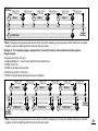
1
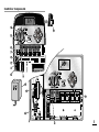
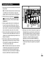
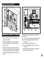
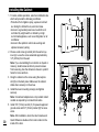
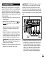
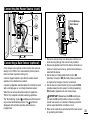
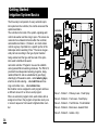
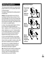
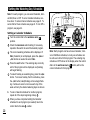
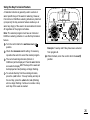
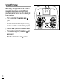
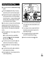
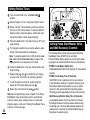
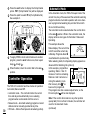
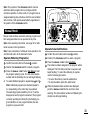
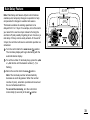
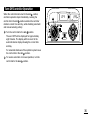
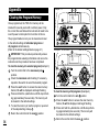
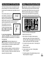
TMC-212
TM
Residential and Commercial Irrigation System Controller
User’s Guide
Congratulations! You have chosen one of the most
sophisticated and technologically advanced irrigation
system controllers available for residential and
light-commercial applications.
Your new Toro TMC-212 controller features:
Flexible Station Count from 2 to 12 Stations with
2-station Expansion modules
Standard and High-surge Expansion Modules
Locking Outdoor Cabinet
Automatic Pump Start/Master Valve Control Circuit
365-day Calendar
3 Fully-independent Watering Programs
4 Start Times per Watering Day
3 Watering day Schedule Options:
7-day Calendar
7-day Interval with Day Exclusion
Odd/Even Days with Day Exclusion
Station Time from 1 minute to 4 hours
Pump Start/Master Valve Timing Control
Well Recovery/Station Delay Time
Season Adjust from 10 to 200 %
Rain Delay from 17 Days
Automatic Program/Start Time Stacking
Rain Sensor Ready
Compatible with All Rain Sensor Types
Sensor Circuit Bypass Switch
Remote Control Ready
Automatic Circuit Protection - Eliminates Fuse
Non-volatile Program Memory - Eliminates Battery
The TMC-212 has some unique features and operating
characteristics. Take just a few minutes to browse
through this manual and familiarize yourself with the
TMC-212 components, installation requirements and
operating features.
The User’s Guide is divided into six main sections:
• The first section provides a brief description of
the controller components and display elements.
• The second section takes you step-by-step through t
he installation process.
• The next section provides fundamental irrigation
system operation, basic controller operation as well
as specific programming and operating characteristics
of the TMC-212.
• The fourth section takes you step by step through the
programming process.
• The fourth section explains the various methods of
automatic and manual controller operations.
• An appendix provides various reference information,
specifications and warranty information.
A watering schedule form (affixed to the cover of the
outdoor model cabinet and included on page 20 of the
User’s Guide for the indoor model) provides a convenient
place to record the location of each watering station area
and specific details of your automatic watering programs.
Table of Contents
Controller Components ...................................2
■
Controller Installation
■
■
■
■
Indoor Model Installation ................................6
❚ Connecting the Valves ....................................7
❚ Connecting a Pump Start Relay......................8
❚ Connecting the Transformer ...........................8
Outdoor Model Installation .............................9
❚ Preparing the Cabinet for Installation..............9
❚ Installing the Cabinet.....................................10
❚ Connecting the Valves ..................................11
❚ Connecting a Pump Start Relay....................12
❚ Connecting the Power Source ......................13
Connecting a Rain Sensor...............................13
■
■
Controller Operations
■
■
Getting Started
■
■
■
■
■
Irrigation System Basics ..................................14
Watering Program Basics ................................15
Watering Program Details................................16
Planning Your Watering Schedule...................18
Filling Out the Watering Schedule Form..........18
❚ Watering Schedule Form ..............................20
Programming the Controller
■
■
■
About the Controller Memory...........................21
Setting the Current Time and Day or Date ......21
Setting the Watering Day Schedule.................22
❚ Setting a Calendar Schedule ........................22
❚ Setting an Interval Schedule .........................23
❚ Setting an Odd or Even Schedule.................24
❚ Using the Day Exclusion Feature .................25
Turning Off a Program ....................................26
Setting Program Start Times ...........................27
Setting Station Times.......................................28
Setting Pump/Master Valve and
Well Recovery Controls ...................................28
■
■
■
Automatic Mode ............................................30
Manual Mode .................................................31
❚ Operate Watering Program(s).......................31
❚ Operate Stations ...........................................31
❚ Watering Control Features ............................32
❚ Pause Watering ..........................................32
❚ Resume Watering .......................................32
❚ Cancel Watering .........................................32
❚ Skip Stations ...............................................32
❚ Adjust the Station TIme During Operation ..33
Rain Delay Feature..........................................33
Season Adjust Feature ....................................34
Turn Off Operation...........................................35
Appendix
■
■
■
■
■
■
■
■
Clearing the Program Memory.........................36
About Automatic Circuit Protection ..................37
Adding a 2-Station Expansion Module.............37
Using Pump/Master Valve Controls.................38
Troubleshooting ...............................................40
Specifications...................................................41
Warranty ..........................................................42
Electromagnetic Compatibility .........................42
1
Controller Components
Controller Components
2
Controller Components
The following are brief descriptions of the controller components and display elements. Each of these items will
be explained in further detail within the appropriate programming, operating and installation sections of this
guide.
1 - LCD Display
2 - Control Buttons
+/ON button – Increases the time display, scrolls forward through the program information and selects
watering days.
–/OFF button – Decreases the time display, scrolls
backward through the program information and
removes watering days.
A - “Start Time” symbol is displayed when setting the
program start times.
NEXT button – Advances to the next portion of program information. Resumes watering if paused.
Advances through stations manually when watering.
B - “Well Recovery” symbol is displayed when well
recovery time delay is in use.
MANUAL START
C - Program start time identification numbers 1–4.
D - Main display of various time values and prompts.
E - Program A, B and C identifiers.
F - “Watering On” symbol is displayed when a watering station is running. Symbol blinks when watering
is paused.
G - “Watering Off” symbol is displayed when Rain
Delay feature is active.
H - “Percent” symbol is displayed when the Season
Adjust feature is in use.
I - Watering Station identification numbers.
J - Day of the week identifiers.
K - “Run Time” symbol is displayed when setting the
watering station run times.
button – Selects and starts manual
watering operations.
3 - Control Dial – Selects all controller programming
and operation controls (except Manual Start).
Control Dial Positions
– The normal dial position for all automatic
and manual operations.
RUN
CURRENT TIME/DAY
– Enables the clock time
and day to be set.
WATERING DAYS
– Enables the watering day
schedules to be set and reviewed.
– Enables the program start times to
be set and reviewed.
START TIMES
– Enables the station run time to
be set and reviewed.
STATION TIMES
(continued)
3
Controller Components
3 - Control Dial Positions (continued)
SEASON ADJUST
– Enables the station time of all
stations in a program to be simultaneously
increased or decreased in 10% increments.
– Provides optional control
and timing features for pump operation and well
recovery delay feature.
SPECIAL FUNCTIONS
– Enables all watering operations to
be delayed from 1 to 7 days.
RAIN DELAY
– Shuts off and prevents all automatic and
manual watering activity.
OFF
4 - Program Select Switch – Three-position slide
switch used to select watering program A, B or C
during the programming procedures and manual
operation.
11 - 2-Station Expansion Module – Each 2-station
expansion module provides connections for two
irrigation control valves. Up to 6 modules for a total
of 12 stations can be installed. Provides 1.3 Kv
surge protection on each output.
12 - Remote Control Receiver Jack – Modular jack
provided for the connection of an optional
Toro Remote Control receiver cable.
(Installation and operating instructions are provided
with the Toro Remote Control system.)
13 - External Transformer – A Plug-in transformer supplies 24 VAC power for the indoor controller models.
5 - Rain Sensor Circuit Control Switch – Enables the
Rain Sensor circuit to be bypassed as necessary.
14 - Internal Transformer – A built-in transformer supplies
24 VAC power to the outdoor controller models.
6 - Rain Sensor Configuration Switch – Configures
the controller for operation with a Normally-open or
a Normally-closed rain sensor.
15 - Input Power Terminal Block – Connection terminals for AC power wires.
7 - Rain Sensor Connection Terminals – Snap-in wire
connectors for direct connection of a Rain Sensor.
8 - Valve Common Connection Terminal – Snap-in
wire connector for the valve common wire.
9-
4
10 - Transformer Connection Terminals – Snap-in
connectors for transformer wires.
Pump/Master Valve Connection Terminal –
Snap-in wire connector for connection of a pump
start relay or master valve 24 VAC power wire.
16 - High-surge 2-station Expansion Module – Each
2-station expansion module provides connections
for two irrigation control valves. Up to 6 modules for
a total of 12 stations can be installed. Provides
6.0 Kv surge protection on each output.
Note: This module can only be used in high-surge
outdoor controller models.
Controller Components
5
A
Controller Installation
F
CAUTION: TMC-212 indoor controller models are
not weather resistant and must be installed indoors
or in a protected location.
B
Indoor Model Installation
C
1. Select a location for the controller within 4' (1.2m) of
an electrical outlet to enable the transformer wires to
easily reach. Make sure the outlet is not controlled by
a light switch.
2. Remove the mounting bracket attached to the back
of the controller housing by pulling the lower edge of
the bracket away and downward from the controller
housing.
3. Place the mounting bracket (A) against the wall aligning the top edge at about eye level. Drive three
1" (25mm) wood screws (B) into the wall through the
three holes provided in the bracket.
Note: If you are installing the bracket on drywall or
masonry, install screw anchors (C) to prevent screws
from loosening.
4. Optional - Insert 3/4" (19mm) PVC conduit (D) for
valve wiring into bracket sleeve (E).
5. Align the slotted openings on the back of controller
housing with the mounting bracket tabs. Slide the
controller downward to engage the tabs.
6
E
D
Note: After installation, store the Quick Reference
Guide and the Watering Schedule Form in the
pocket (F) behind the controller.
Connecting the Valves
11
2. Attach the white-color cable wire to one wire from
each valve solenoid. (Either solenoid wire can be
used for this connection.) This is called the valve
common wire.
3. Attach a separate cable wire to the remaining wire
from each valve solenoid. Make a note of the wire
color code used for each valve and the watering station it controls. You will need to have this information
when connecting the valve wires to the controller.
4. Secure all wire splices using twist-on wire connectors.
To prevent corrosion and possible short circuits, use
a grease cap or similar waterproofing method to insulate each connection.
5. Route the wire cable into the controller through the
large opening in the base of the housing or through
PVC conduit if it is installed. Strip insulation back
1/2" (13mm) from all cable wires.
DIS
ENB
NO
Note: The station modules and wire connectors accept
14–18 AWG (2.5–1.0mm2).solid-core copper wire.
Sprinkler system connection cable is recommended.
NC
1. Route the valve control wires between the valves and
the controller.
8
9
Master
Valve
Valve Common
Wire
Station
Valves
6. Referring to the Controller Components on page 5 and
the diagram above, secure the valve common wire to
the terminal labeled COM (8). Connect the individual
station valve wires to the appropriate station module
terminals (11). Connect the master valve wire (if
applicable) to the terminal labeled PUMP/MV (9).
Note: Connecting a master valve or pump start relay
is optional and may not be required in your sprinkler
system.
Note: The station module has snap-in wire connectors
To attach wires, simply raise the lever and insert the
bare wire end into the small hole beneath the lever.
Press the lever down to secure the wire. Pull lightly on
the wire to confirm that it is locked into the module.
7
Connecting a Pump Start Relay
Connecting the Plug-in Transformer
CAUTION: Never connect an auxiliary pump
starter directly to the controller. A 24 VAC relay,
rated at 0.30A maximum current draw, must be used
to connect the controller to the pump starter circuit.
1. Route a wire pair from the pump start relay into the
controller housing.
2. Connect one wire to the valve common COM (8).
Connect the remaining wire to the PUMP/MV (9) as
shown below.
1
2
3
4
5
6
7
8
CAUTION: Do not plug the transformer into an
electrical outlet until all of the wiring procedures have
been completed.
1. Route the cable from the transformer (13) through
the small opening provided in the base of the housing.
Wrap the cable around and through the restraining post
as shown below.
10
9
Jumper Wire
8
9
9V
24 VAC Pump Start Relay
Valve Common Wire
CAUTION: If the pump does not have an automatic pressure control switch, prevent pump damage
due to “dead-heading,” by connecting a jumper wire
from any unused station terminal to a station terminal
with a valve wire connected.
8
13
Note: Refer to “Pump Control and Well Recovery” section
on page 28 for important pump circuit control information.
2. Connect one transformer cable wire to each terminal
labeled 24 VAC (10). The wires can be connected to
either terminal.
Note: The display will begin flashing 12:00 a.m. Press
any button to stop the display from flashing.
Outdoor Model Installation
ON
ON
MA
MANUNUAL
ST AL
STARAR
T
T
NE
NEXTXT
B
OF
OFF F
C
A
Preparing the Cabinet for Installation
1. Remove the lower housing cover (A) by pulling
outward on the handle.
2. Remove two phillips screws from the transformer
access cover (B). Pull the cover outward from the
bottom to remove.
3. Three lower mounting holes (C) are provided. The
center hole is open and the outer holes are plugged.
If you intend to use the outer holes for installation,
carefully drill through the plugs with a 3/16" (5mm)
drill bit.
D
E
F
G
Four wiring access holes are provided in the cabinet
base as follows:
(D) - 1/2" (13mm) for power and equipment ground wires.
(E) - 1/2" (13mm) (plugged) for optional Toro Rain
Sensor wires.
(F) - 3/4" (19mm) for sprinkler valve wires.
(G) - 1/2" (13mm) (plugged) for optional Toro remote
control cable.
4. If planning to install the optional Toro components,
remove the plugs as necessary.
9
Installing the Cabinet
1. For safe, reliable operation, select an installation site
which will provide the following conditions:
• Protection from irrigation spray, exposure to direct
sun during the hottest hours, wind and snow.
• Access to a grounded power source which is not
controlled by a light switch or utilized by a high
current load appliance, such as a refrigerator or air
conditioner.
• Access to the sprinkler control valve wiring and
optional accessory wiring.
A
B
6" (15.24cm)
2. Drive a wood screw (provided) into the wall at eye
level (A). Leave the screw extended approximately
1/4" (6.5mm) from the wall.
Note: If you are installing the controller on drywall or
masonry, install screw anchors to prevent screws
from loosening. Use the dimension shown to predrill
holes for screw anchors.
3. Hang the cabinet on the screw using the keyhole
slot (B) on the back panel. Make sure the cabinet
slides down securely on the screw.
4. Install the lower mounting screw(s) and tighten
securely.
Note: Conduit and adapters are not provided. Install
conduit as required by local electrical codes.
5. Install 1/2" (13mm) conduit (C) for power/equipment
ground wires and 3/4" (19mm) conduit (D) for valve
wires.
10
Note: After installation, store the User’s Guide and
Quick Reference Guide on the hook located on the
inside of the door.
C
D
Connecting the Valves
Note: Using 16 to 18 AWG (1.5mm2 to 1mm2) irrigation
cable is recommended. This cable is made specifically for
automatic irrigation systems and is available in several
lengths and conductor count. Always use a cable that has
at least one wire for each valve and one wire for the valve
common connection.
1. Route the wire cable from the valve location into the
controller cabinet.
IMPORTANT: The TMC-212 has snap-in wire terminals. To attach wires, simply raise the lever, insert the
stripped end of the wire, then press the lever down to
secure the connection. After securing a wire, inspect the
connection to verify a small portion of bare wire is visible
to ensure that insulation is not present in the wire contact
area.
11
2. Attach the white color-coded cable wire to one wire
from each valve solenoid. This is called the valve
common wire.
Note: The solenoid does not have specific polarity,
so either wire can be used for the common wire
connection).
3. Connect an individual color-coded cable wire to the
remaining solenoid wire of each valve. Make a note
the wire insulation color used for each valve connection and the sprinkler zone controlled by the valve.
IMPORTANT: Properly insulate and waterproof all
solenoid wire connections and cable wire splices to
prevent short circuit conditions.
4. Remove 1/2" (13mm) of insulation from the end of all
cable wires to be connected to the controller.
8
9
Master
Valve
Valve Common Wire
Station
Valves
5. Referring to the Controller Components on page 5 and
the diagram above, secure the valve common wire to
the terminal labeled COM (8). Connect the individual
valve wires to the appropriate expansion module terminals (11). The stations are numbered from left to
right, 1 through 12. Connect the master valve wire
(if applicable) to the terminal labeled PUMP/MV (9).
11
Connecting a Pump Start Relay
CAUTION: To prevent controller damage, never
connect an auxiliary pump starter directly to the
controller’s 24 VAC output. A 24 VAC 0.30A relay,
must be used to connect the controller to the pump
starter circuit.
1. Route a wire pair from the pump relay into the controller housing.
2. Connect one wire to the terminal labeled COM (8).
Connect the remaining wire to the terminal labeled
PUMP/MV (9) as shown below.
Jumper Wire
8
Connecting the Power Source
WARNING:
AC power wiring must be installed and connected
by qualified personnel only. All electrical components and installation procedures must comply
with all applicable local and national electrical
codes. Some codes may require a means of disconnection from the AC power source installed in the
fixed wiring and having a contact separation of at
least 0.120" (3mm) in the line and neutral poles.
Make sure the power source is OFF prior to connecting the controller.
1. Route the power and equipment ground wires from the
power source, through the conduit and into the controller transformer compartment.
Note: The controller terminal block accepts wire size
up to 12 AWG (4mm2).
9
2. Remove 3/8" (10mm) insulation from the wire ends.
Pump Start
Relay
Valve Common Wire
CAUTION: To prevent pump damage due to prolonged dead-head pressure, connect a jumper wire
from an unused station terminal to a terminal with a
with a valve connected.
12
Note: Refer to “Pump Control and Well Recovery” section
on page 28 for important pump circuit control information.
3. Using a small flat blade screwdriver, secure the wires
as shown to the terminal block as follows:
Line or Line 1 (L1) to L, Neutral or Line 2 (L2) to N
and Equipment Ground to
.
4. Install and secure the transformer compartment
cover.
5. Apply power to the controller.
Note: The display will begin flashing 12:00 AM. Press any
button to stop the display from flashing.
Connecting the Power Source (cont.)
Toro Wireless
Rain Sensor
5
5
6
6
Connecting a Rain Sensor (optional)
A rain sensor is an optional control device that connects
directly to the TMC-212 to automatically interrupt automatic controller operation during rain.
A sensor bypass switch is provided to enable sensor
operation to be disabled as needed.
A sensor configuration switch enables the controller to work
with a normally-open or a normally-closed rain sensor.
When the rain sensor absorbs moisture it signals the
TMC-212 to suspend automatic watering operations.
The “No Watering” symbol is displayed until the sensor
drys out and automatically resets. The symbol will
disappear and controller operation will resume as
programmed.
1. Route the sensor wires from the device into the controller housing through the access hole provided.
2. Remove the plastic insert from the Sensor terminal connectors. Connect sensor wires per the instructions provided with the device.
3. Set the Sensor Configuration Switch (5) to NC
(Normally Closed) or NO (Normally Open) operation
as required by the type of sensor connected.
4. Set the Sensor Control Switch (6) as required: ENB
(enable) allows the rain sensor to interrupt watering;
DIS (disable) bypasses the rain sensor input.
IMPORTANT: Do not use the ENB switch position with the NC switch position unless a normallyclosed rain sensor is connected. Watering operation
will be suspended if this condition occurs.
5. Refer to the instructions provided with the rain sensor
for operating information.
13
Getting Started –
Irrigation System Basics
The three major components of every automatic sprinkler system are the controller, the control valves and the
sprinklers/emitters.
The controller is the brain of the system, signaling each
control valve when and how long to open. The valves are
connected to numbered terminals within the controller,
and identified as Station 1, Station 2, etc. Each station
controls a group of sprinklers in a specific portion of the
landscape called a watering “Zone.” The zones are generally laid out according to the type of plant material
being watered and the type and flow rate of the sprinklers used to distribute the water.
Automatic controller “Programs” are used to establish
and organize different watering schedules. The TMC-212
provides three independent watering programs, designated A, B and C. and are established by specifying:
what day(s) of the week to water – called watering days,
what time to start watering – called start time and how
long each station runs – called station time.
Each station can be assigned to each program and have
a different amount of run time in each program.
When an automatic program starts, each station with an
assigned run time in the program will operate one by one
in numeric sequence from lowest to highest station number
Controller
Valve 1
Valve 2
Valve 3
House
Valve 4
Valve 5
Valve 1 - Station 1 - Parkway Lawn - Fixed Spray
Valve 2 - Station 2 - Front Lawn - Fixed Spray
Valve 3 - Station 3 - Front Shrubs - Flood Bubbler
Valve 4 - Station 4 - Back Lawn - Geared Rotor
Valve 5 - Station 5 - Garden - Drip
14
Watering Program Basics
The following example illustrates how a typical watering
program could be set up for the sprinkler system shown
on the previous page.
The diagram at the right depicts the watering program in
a timeline format.
Example: The program start time is set for 3:00 a.m.
Lawn stations 1 and 2 each have a run time of 10 minutes and lawn station 4 is set to run for 20 minutes. Note
that stations 3 and 5 water shrubs and flowers and have
been excluded from this program. (These stations will be
set to operate on a separate program).
As shown in the watering program diagram, at 3:00 a.m.
the controller starts the program watering cycle.
Station 1 sprinklers run for 10 minutes and shut off. Next,
station 2 sprinklers turn on, run for 10 minutes and shut
off. The controller skips station 3, and turns on station 4
which runs for 20 minutes and shuts off. Station 5 is
skipped and the watering cycle ends at 3:40 a.m.
As you can see from this example, only one program
start time was needed to operate three different stations.
Using more than one program for example, would enable
lawn zones to be watered every day on program A,
shrub zones to run on on Monday, Wednesday and
Friday on program B and drip irrigation to soak the
flower beds every three days on program C.
Watering Program Diagram
Program Starts
at 3:00 a.m.
Station 1
Station time
10 minutes
12
3
9
6
12
Station 2
Station time
10 minutes
3
9
6
12
Station 4
Station time
20 minutes
Program Ends
at 3:40 a.m.
3
9
6
Note: Although the TMC-212 offers the multiple program
feature, you may want to use one program only if it
meets your needs. The remaining programs can be
turned off and on as you need to use them.
15
Watering Program Details
This section covers in detail each of the three parts of a
watering program: watering days, program start times
and station times.
Selecting a Watering Day Schedule
The TMC-212 provides three optional formats for scheduling watering days: Calendar, Interval, Odd or Even.
The Calendar Format
The Calendar format is a recurring 7-day schedule that
begins on Sunday and enables you to select specific
days of the week to water.
This illustration shows how a
Calendar schedule would be displayed when the control dial is in the
WATERING DAYS
position.
In this example, program A has watering days set for
Monday (MO), Wednesday (WE) and Friday (FR).
The Interval Format
The Interval format provides a periodic watering day
schedule ranging from 1 (every day) to 7 (every-7th day)
in one-day increments. For example, to water every third
day, you would select a 3-day interval.
Since the interval schedule is not tied to specific days of
the week, you will need to determine when the interval
will start by selecting the initial watering day.
For example, if you have selected a 3-day Interval and
today is Sunday, you may choose to have the first day of
the Interval on Sunday, Monday or Tuesday. From that
point on, two days will be off and the third day will water.
16
This illustration shows how an
Interval schedule would be displayed.
In this example, program B has a
3-day Interval schedule set to begin
on Monday.
Odd/Even Format
The Odd/Even format enables you to select all odd or all
even numbered days of the month as watering days.
This illustration shows how an
Odd day schedule would be
displayed.
Day Exclusion Feature
Since the Interval and Odd/Even watering day formats
are not tied to actual calendar days, the Day Exclusion
feature enables you to prevent specific days of the week
from watering. For example, due to water conservation
restrictions, watering is not permitted on Monday. Also,
the lawn is mowed on Friday, so Friday is also excluded.
This example shows the days excluded (dE) are Monday and
Friday in watering program A.
Program Off
Selecting OFF suspends the operation of the program
when it is not needed. Turning the program off does not
alter or erase the program information.
This illustration shows how a
program would be displayed if is
turned off. In this example, program
C is off.
Selecting Program Start Times
Setting the Station Time
A program start time is the time of day an automatic
program watering cycle is set to begin. Sometimes it is
necessary to run a watering program more than one time
per day, for example, when establishing a new lawn.
The TMC-212 enables each watering program (A, B and
C) to have four independent start times.
Please note the following start time conditions:
• A watering program requires only one start time to
operate automatically.
• A start time is assigned to a watering program, not to
an individual station.
• When a start time occurs, the stations with operating
time assigned in the program will be operated one at a
time (for their set duration) in numeric sequence.
• If a program start time occurs while the controller is
already running a watering cycle, the start will be
delayed until the current watering cycle concludes (this
is known as “Stacking”).
Program start times are displayed as 1 through 4. These
numbers are shown at the top left of the display next to
the start time symbol when the control dial is in the
START TIME
position.
Station time is the amount of time a station’s control valve
stays open during a watering cycle. Station time can be set
from 1 minute to 4 hours (in 1-minute increments).
This illustration shows how a
program start time is displayed.
In this example, program A
has one start time (start time
number 1) set for 3:00 a.m.
When setting a station time, the first step is to select a
watering program. When a station is given a time of at
least 1 minute, it is assigned to the program. A station is
removed from a program by setting it’s time to “Off.”
Each station can have a time assignment in each program.
For example, station 1 could be set to run for 15 minutes in
program A, 10 minutes in program B and Off in program C.
All stations assigned to the program are shown on the
lower portion of the display when the control dial is in the
STATION TIMES
position.
The run time symbol is displayed when station time is
being set. The displayed time is assigned to the flashing
station number.
This example shows how
station time is displayed.
Stations 1, 2 and 4 are assigned
to program A. Station 1 and 2
are set for 10 minutes and
station 4 is set for 20 minutes.
Stations 3, 5 and 6 are not displayed because they do not
have an assigned time in
program A.
Flashing
Flashing
Flashing
17
Planning Your Watering Schedule
It is always helpful to have your initial watering schedule
organized on paper before beginning the programming
steps. The information can be recorded on the Watering
Scheduling form located inside the cover of the outdoor
controller or on the blank form provided on page 20.
Guidelines for Watering
There are several factors to considered when determining how much to water. For example, the soil composition, the type of lawn and plants, exposure to sun and
shade and the rate at which the sprinklers apply water.
Because of these variables, an exact schedule can not
be provided. Some trial and error will be required to find
the best watering schedule, but here are some general
watering guidelines to help you get started.
• Water two or three hours before sunrise. You will have
the best water pressure at this time and evaporation
will be minimal.
• With a new lawn, water frequently for a short duration
to keep the soil and plants moist at all times until
established. Cut back on watering if runoff occurs.
• With an established landscape, water enough to
saturate the plants and soil without causing runoff.
Gradually cut back watering over a period of time until
you notice signs of plant stress. Increase watering
gradually just enough to regain plant health and vitality.
This watering method enables a healthy landscape to
be maintained using the least amount of water.
18
Filling Out the Watering Schedule Form
• Location - Identify the portion of the landscape
watered by each station.
Note: Enter the following information for each program
(A, B and C). If a program is not needed, leave its
information column blank.
• Watering Day Schedule - For a Calendar schedule,
circle the day(s) of the week watering is desired. For
an Interval schedule circle the desired Interval number. For Odd or Even days, simply mark the appropriate box. If you need to restricted watering on certain
days, circle the excluded day(s).
• Station Time - Indicate the amount of operating time
(1 minute to 4 hours) for each station. Write “Off” for any
station which you do not want to assign to the program.
• Well Recovery Delay Time - Well recovery time is
indicated her. See “Pump Control and Well Recovery”
on pages 28 and 29 for detailed information.
• Program Start Times - Indicate the time of day to
start the program. Each program can have up to 4
separate start times.
Note: The TMC-212 can operate only one program
at a time. Within that program, only one station can
operate at a time. Therefore, when using more than
one program or using more than one start time in a
program, make sure that each watering cycle can run
to completion before the next watering cycle starts. A
start time that occurs while a watering cycle is already
in progress will be delayed until the active watering
cycle is finished. If the start time is delayed past Midnight into the next day, the start will be ignored if the
day is not scheduled as an active watering day.
(Example)
Watering Schedule Form
PROGRAM A
CALENDAR
INTERVAL
WATERING
DAY SCHEDULE
1
2
3
4
5
6
7
8
9
10
11
12
ODD
3
4
5
6
EVEN
STATION RUN TIME
LOCATION
Parkway Lawn
Front Lawn
Front Shrubs
Back Lawn
Garden
WELL RECOVERY DELAY TIME
1
PROGRAM
START TIMES
2
7
1
2
ODD
3
4
5
6
EVEN
7
1
2
ODD
3
4
5
6
7
EVEN
SU MO TU WE TH FR SA SU MO TU WE TH FR SA SU MO TU WE TH FR SA
EXCLUDE
STATION
PROGRAM C
SU MO TU WE TH FR SA SU MO TU WE TH FR SA SU MO TU WE TH FR SA
1
ODD/EVEN
PROGRAM B
2
3
4
STATION RUN TIME
STATION RUN TIME
10
10
Off
25
Off
Off
Off
20
Off
Off
Off
Off
Off
Off
1 hr
10
2:30 am
Off
Off
Off
4:00 am
Off
Off
Off
5:00 am
Off
Off
Off
19
Watering Schedule Form
PROGRAM A
CALENDAR
WATERING
DAY SCHEDULE
1
ODD/EVEN
ODD
3
4
5
6
EVEN
STATION RUN TIME
1
2
3
4
5
6
7
8
9
10
11
12
WELL RECOVERY DELAY TIME
1
2
3
4
20
2
7
1
2
ODD
3
4
5
6
EVEN
7
1
2
ODD
3
4
5
6
7
EVEN
SU MO TU WE TH FR SA SU MO TU WE TH FR SA SU MO TU WE TH FR SA
LOCATION
PROGRAM
START TIMES
PROGRAM C
SU MO TU WE TH FR SA SU MO TU WE TH FR SA SU MO TU WE TH FR SA
INTERVAL
EXCLUDE
STATION
PROGRAM B
STATION RUN TIME
STATION RUN TIME
Programming the Controller
Setting the Current Time and Date
About the Watering Program Memory
Once programmed, the TMC-212 memory will be
retained for several years without power. Only the current time and date information will be lost and will need
to be reset if power is interrupted from the controller for
more than 24 hours.
The TMC-212 has a permanent (default) watering program
that will automatically control your sprinkler system when
power is lost.
The default settings are as follows:
• Program A has a Calendar watering schedule set to
water every day. Programs B and C are turned Off
• One program start time set for 5:00 a.m.
• Station time set to 10 minutes per station
• Pump Start/Master Valve circuit is On.
• Pump Start/Master Valve circuit delay is 2 seconds
• Well Recovery time is 0 seconds.
• Pump Start/Master Valve circuit is enabled during Well
Recovery time.
• Season Adjust is 100%
If you do not wish to program the controller, you can
use the default settings as is. To enable the TMC-212
controller to operate Automatically in real time, set
the current time, day and date.
Note: The controller’s programmable memory can be reset
to the default settings at any time. See “Clearing the Program Memory” on page 36 for detailed information.
5
Day
Month
Turn the control dial to the CURRENT TIME/DAY
position (the hour digits will begin flashing).
Note: The time of day will be displayed in hours and
minutes (12-hour format). To select a 24-hour format,
press the next button repeatedly to display 12 H. Press
the +/ON button to display 24 H. Press the next button
once (the hour digits will begin flashing).
To increase the display value, press the +/ON button;
to decrease, press the –/OFF button.
Note: The display characters will change rapidly when
holding the +/ON or –/OFF button down for more than two
seconds.
Press the NEXT button to select the next portion of
the display.
4. Repeat steps
and
to set the following current
information: minutes, year, month and day.
When the current time and day are displayed, return
the control dial to the RUN position.
21
Setting the Watering Day Schedule
Note: For each program, you can select Calendar, Interval Odd, Even or Off. To set a Calendar schedule, continue here. To set an Interval schedule see page 23. To
set an Odd or Even schedule see page 24. To turn Off a
program, see page 24.
2
3
7
4
5
3 5
Setting a Calendar Schedule
Turn the control dial to the WATERING
position.
Check the PROGRAMS switch setting. If necessary,
reposition the switch to select the desired program.
The current watering schedule will be displayed. If
CAL (Calendar) is not displayed, press the +/ON or
–/OFF button as needed to select CAL.
Press the NEXT button. The watering days currently
set for this program will be displayed. SU (Sunday)
will begin flashing.
To select Sunday as a watering day, press the +/ON
button. To remove Sunday from the schedule, press
the –/OFF button; MO (Monday) will now begin flashing. Continue to select or remove each day of the
week until only the desired watering days are shown
6. To set a Calendar schedule for another program,
repeat all of the steps beginning at step
.
When you have completed setting the Calendar
schedule for each program (as needed) return the
control dial to the RUN position.
22
4
DAYS
3 5
Note: Each program can have its own Calendar, Interval or Odd/Even schedule, but only one schedule can
be active at a time for that program. The watering day
schedule or OFF shown in the display when the control
dial is in the WATERING DAYS
position, will be the
current schedule for that program.
Setting an Interval Schedule
3 2
Turn the control dial to the WATERING
position.
DAYS
Check the PROGRAMS switch setting. If necessary,
reposition the switch to select the desired program.
The current watering schedule will be displayed. If
Int (Interval) is not displayed, press the +/ON or
–/OFF button as needed to select Int.
Press the NEXT button. The current Interval number
(1–7) will begin flashing. The day of the week on
which the Interval will start will be shown.
9
6
7
4
5
3 5
7
1
4 6
3 5
7
To change the Interval number, press the +/ON or
–/OFF button until the desired number is flashing.
Press the NEXT button. The Interval start day will
begin flashing.
To change the Interval start day, press the +/ON
button or the –/OFF button until the desired day is
flashing.
8. To set an Interval schedule for another program,
repeat all of the steps beginning at step .
When you have completed setting the Interval
schedule for each program (as needed), return the
control dial to the RUN position.
Note: The Day Exclusion feature enables you to
select any day(s) of the week to be excluded and
remain off when using an Interval or Odd/Even
watering schedule.
See page 25 for detailed information.
23
Setting an Odd or Even Schedule
3
Turn the control dial to the WATERING
position.
Check the PROGRAMS switch setting. If necessary,
reposition the switch to select the desired program.
The current watering schedule will be displayed. If
Odd or Even is not displayed, press the +/ON or
–/OFF button as needed to select Odd or Even.
Note: When Odd is selected, the 31st day of the
month and the 29th day of a leap year will not be
active watering days.
4. To set an Odd or Even schedule for another
program, repeat steps
and
as needed.
When you have completed setting the Odd or Even
schedule for each program as needed, return the
position.
control dial to the RUN
Note: The Day Exclusion feature enables you to
select any day(s) of the week to be excluded and
remain off when using an Interval or Odd/Even
watering schedule. See page 25 for detailed information.
24
2
DAYS
5
3
1
3
Using the Day Exclusion Feature
A Calendar schedule is generally used to exclude or
select specific days of the week for watering. However,
if an Interval or Odd/Even watering schedule is preferred
(or required), the day exclusion feature enables you to
select any day(s) of the week to be excluded and remain
off regardless of the program schedule.
Note: The selected program must have an Interval or
Odd/Even watering schedule to use the Day Exclusion
feature.
Turn the control dial to the WATERING
position.
DAYS
Check the PROGRAMS switch setting. If necessary,
reposition the switch to select the desired program.
The current watering schedule (Interval or
Odd/Even) will be displayed. Press the NEXT button
as needed to display d E. The days of the week will
be displayed and SU (Sunday) will begin flashing.
Example: Tuesday and Friday have been excluded
from program A.
When finished, return the control dial to the RUN
position.
To exclude Sunday from the watering schedule,
press the –/OFF button. To keep Sunday and skip to
the next day, press the +/ON button; MO (Monday)
will now begin flashing. Continue to exclude or skip
each day of the week as needed.
25
Turning Off a Program
3
Note: Turning off a program does not alter or erase a
preset watering day schedule. Selecting Off simply
places the program on hold until one of the watering day
formats is selected.
Turn the control dial to the WATERING
position.
DAYS
2
5
3
1
Check the PROGRAMs switch setting. If necessary,
reposition the switch to select the desired program.
Press the +/ON or –/OFF button until OFF is flashing.
4. To turn another program Off, repeat steps
as needed.
Return the control dial to the RUN
26
position.
and
3
Setting Program Start Times
Turn the control dial to the PROGRAM
position.
3
9
2
START TIME
12
Check the PROGRAMS switch setting. If necessary,
reposition the switch to select the desired program.
Program start time number 1 will begin flashing. The
current program start time or OFF will be displayed
for start time number 1. To select a different program
start time number, press the +/ON or the –/OFF button until the desired number is flashing.
Note: The numbers (1–4) shown at the top of the display
designate program start times and should not be confused with station numbers. The station numbers will be
shown at the bottom of the display when setting station
run time.
Press the NEXT button. The hour digit(s) or OFF will
begin flashing.
Note: To remove the start time, select OFF by
pressing the +/ON and –/OFF buttons at the same
.
time, and continue at step
4 5
6 7
3 5 7
9
4 6 8
1
3 5 7 9
To select another start time number, press the +/ON
or the –/OFF button until the desired start time number is flashing.
10. To set, change or remove a program start time for
the start time number selected, repeat all of the
steps starting at step
.
11. To set program start times for another program,
repeat all of the steps starting at step
.
Return the control dial to the RUN
position.
To set the hour (and AM/PM), press the +/ON or the
–/OFF button until the desired hour is flashing.
Press the NEXT button. The minute digits will begin
flashing.
To set the minutes, press the +/ON or –/OFF button
until the desired minute is flashing.
Press the NEXT button. The next program start time
number will begin flashing.
27
Setting Station Times
Turn the control dial to the
position.
2 2
PGM A
STATION TIMES
99
1 2 3 4 5 6
Select Program A, B or C using the Program switch
Station number 1 will be flashing and its current station time or OFF will be shown. To select a different
station number, press the +/ON or –/OFF button until
the desired station number begins flashing.
Press the NEXT button. The station time (or OFF) will
begin flashing.
To change the station time, press the +/ON or –/OFF
button until the desired time is displayed.
Note: To reset the station time to Off, press the +/ON
and –/OFF buttons at the same time, or reduce the
displayed time to one step past 0:01 minute.
Press the NEXT button. The next station number will
begin flashing.
7. Repeat steps
and
as needed to set, change,
or remove the run time for the remaining stations.
8. To set the station run time for another program,
repeat all of the steps starting at step
.
Return the control dial to the RUN
position.
Note: Basic programming is now complete. If the Pump
Start/Master Valve circuit will be used to automatically
control a master valve, auxiliary pump or a well water
irrigation supply, continue at “Setting Pump/Master Valve
Controls” on the next page.
28
44 5 5
3 5
3 5
3
4 5
4 5
1
1
2
3 5
3 5
Setting Pump Start/Master Valve
and Well Recovery Controls
The following timing control features enable the Pump
Start/Master Valve (PS/MV) circuit and Well
Recovery/Station Delay options to be set for each watering program as needed. (Defaults shown in parenthesis.)
• PS/MV Circuit Master Switch (On)
Enables/disables PS/MV circuit operation for the selected
program.
• PS/MV Circuit Delay Time (2 Seconds)
The PS/MV circuit is switched on for 2 seconds prior
to the first station starting in a program watering cycle.
The delayed station start enables a pump or master
valve to be fully operational before watering begins.
The delay period is adjustable from two to 60 seconds.
• Well Recovery/Station Delay Time (0 Seconds)
An adjustable duration from 0 seconds to 60 minutes
that delays the start of each successive station during
a watering cycle. The time delay between stations can
enable a well or reservoir to maintain sufficient supply
throughout the watering cycle.
• PS/MV Circuit Enabled During Well Recovery (Yes)
This timing control feature enables the PS/MV circuit to
be active (Yes) or inactive (No) during a Well Recovery
/Station Delay time period.
Note: Refer to Appendix A on page 40 for typical examples
of the PS/MV circuit and Well Recovery timing control
features in use.
Example 1
Press the NEXT button to display the Well Recovery
delay time. The well recovery symbol
and S 00
(zero seconds) will be displayed. See Example 2.
Example 2
Seconds
Minutes
10
2
7
8
7
5
3
9
6
8
5
1
4
6
Turn the control dial to the SPECIAL FUNCTIONS
position. See Example 1.
Check the PROGRAMS switch setting. If necessary,
reposition the switch to select the desired program.
3. The display will show P On (Pump On) and will
begin flashing.
To disable the PS/MV circuit operation for this
program, press the –/OFF button; P OFF (Pump Off)
will be displayed.
Press the NEXT button to display the Pump Delay
time. Pd 02 (two-second delay) will be displayed.
Press the +/ON or –/OFF button to select a delay time
duration from 02 to 60 seconds.
Press the +/ON or –/OFF button to set the recovery
or station delay duration from 02 to 60 seconds or
01 to 60 minutes. The display will change from
S (seconds) to M (minutes) as the time is increased
past 60 seconds.
Note: The well recovery symbol
will be displayed
when this timing control feature is used.
(continued)
29
Press the NEXT button to display the Pump Enable
option. PE Y (Pump Enable Yes) will be displayed.
Press the –/OFF to select PE n (Pump Enable No).
See example 3.
Example 3
12
10
11
10
11
To apply PS/MV circuit control features to another
program, press the NEXT button once, then repeat
steps through
.
When finished, return the control dial to the RUN
position.
Controller Operation
30
The TMC-212 controller has three modes of operation:
Automatic, Manual and Off.
• Automatic mode – The controller tracks the current
time and day and automatically runs a watering
programs when a scheduled start time occurs.
• Manual mode – Automatic watering programs or select
stations can be manually operated at any time.
• Off mode – Shuts off and prevents all watering activity.
Automatic Mode
In the Automatic mode, the TMC-212 keeps track of the
current time, day of the week and the automatic watering
program schedule. Automatic operation will occur whenever a programmed watering day and start time match
the current time and day.
The Automatic mode is selected when the control dial is
in the RUN position. While in the automatic mode, the
display will show two types of information: Status and
Operating.
This example shows the
Status display. The current time
is 2:45 PM and the current day
is Monday. Programs A and B
are scheduled to operate today.
When watering starts, the Operating display appears as
shown with the Watering On symbol .
In this example, program A is
Flashing
operating. Station 1 has 10
minutes of run time remaining.
Stations 2 and 3 will also run
during this watering cycle.
Flashing
Well recovery time has
been set for program A.
This program also has a season adjust factor, so the
Percent symbol will be also displayed.
Note: If the control dial remains in any other position
(except OFF) for more than 8 minutes, the controller will
revert to the Automatic mode.
(continued)
Note: The position of the PROGRAMS switch does not
determine which program will run during automatic
controller operation. In other words, if a program has an
assigned watering day schedule, start time and a station
with run time, it will operate automatically regardless of
the position of the PROGRAMS switch.
Manual Mode
Flashing
1
4
3 5
Manual mode enables automatic watering programs and
their assigned stations to be operated at any time.
Note: Once watering has started, see page 32 for additional manual control operations.
Note: Upon completion of a Manual mode operation, the
controller will return to the Automatic mode.
Operate Watering Program(s)
Confirm the control dial is in the RUN
position.
Position the PROGRAMS switch to select a program.
Press the MANUAL START button two times to start
the program watering cycle. The first active station
number and the Watering On icon will begin flashing.
4. To select additional programs, repeat steps
and .
Note: Additional programs are stacked (staged to
run sequentially) in the order they are selected.
The watering program identifier (A, B or C) will be
displayed as each program is selected. The program
currently operating is indicated by the flashing program identifier. As one program finishes the next
program in queue will start.
4
Operate Selected Stations
Confirm the control dial is in the RUN
position.
Position the PROGRAMS switch to select a program.
Press the MANUAL START button one time.
The station numbers assigned to the program will be
displayed. The first station number in sequence will
begin flashing. To select the station(s) to operate,
use the following procedure:
• To select the station, press the +/ON button.
• To skip the station press the –/OFF button.
When the desired station numbers are displayed,
press the MANUAL START button one time to start
watering. The active station number and Watering On
droplet icon will begin flashing.
31
Watering Control Features
Once the sprinkler system is running, the following manual control features become available:
Pause Watering
Press the +/ON and the –/OFF buttons at the same time.
• The station will temporarily turn off.
• The “Watering On” symbol will begin flashing.
• The display will show the amount of station time
remaining.
Note: If watering is not resumed within 8 minutes,
all watering operations will be canceled and the
controller will return to the automatic mode.
To resume operation, press the NEXT button.
• Watering activity will resume from the point of
interruption.
Two methods of canceling watering are available:
Press the +/ON and –/OFF buttons at the same time two times.
• All watering operations will be canceled and the controller will return to the automatic mode.
32
Press the NEXT button one time.
• The station currently watering will shut off and the
next station will start.
• If the last station is skipped, the program will end.
If additional programs have been set to operate,
the next program in alphabetical order will start.
To Adjust the Station Run Time:
Press the +/ON button to increase run time or the –/OFF
button to decrease run time.
• If the station run time is decreased to less than
1 minute, the station will shut off. The next station
in sequence will start.
• The station run time is changed during this operation
only. The program memory will not be changed.
Cancel Watering
Note: Placing the control dial in the OFF
will
two seconds, then back to RUN
also cancel all watering operations.
To Skip Stations:
position for
Rain Delay Feature
Flashing
Note: Rain Delay and Season Adjust control features
enables quick, temporary changes in operation to help
compensate for changes in weather and season.
This feature enables all watering operations to be
delayed from 1 to 7 days. For example, rain is forecast in
your area for the next two days. Instead of turning the
controller off (and possibly forgetting to turn it back on), a
rain delay of 3 days can be easily entered. At the end of
3 days, the controller will resume automatic operation as
scheduled.
3
2
1
2
position.
Turn the control dial to the RAIN DELAY
The rain delay display will begin alternating with the
automatic status display.
To set the number of rain delay days, press the +/ON
or –/OFF button until the desired number (1–7) is
flashing.
Return the control dial to the RUN
position.
Note: The rain delay number will automatically
decrease as each day passes. When the number
reaches 0 (zero), automatic operation will resume at
the next scheduled start time.
To cancel the rain delay, turn the control dial
momentarily (4 seconds) to the OFF position.
33
Season Adjust % Feature
Note: The Rain Delay and Season Adjust % features
modify controller operation only and do not alter the controller’s programmable memory.
5
3
The Season Adjust % feature enables the station time of
all stations (assigned to a watering program) to be simultaneously decreased or increased from 10–200% in 10%
increments.
For example, selecting a 50% factor decreases all stations to half of their programmed station time. A station
programmed for 20 minutes would run 10 minutes and a
station with 15 minutes would run 7 minutes and 30 seconds. As a conservation measure, an increase above
100% time calculates the increased time and splits the
time in half. The program watering cycle then runs
through twice consecutively. This method of increasing
irrigation enables more water to soak into the plant root
zone instead of pooling and running off.
For example, adjusting to 150% will first increase a
20-minute station time to 30 minutes (1.5 x 20 = 30).
The controller automatically divides 30 minutes in half
and runs the station for 15 minutes in back-to-back
watering cycles.
Note: All station times are retained in the controller’s
programmable memory and returned to their set value
when the season adjust is reset to 100%. The adjusted
station time will be displayed during operation.
The % symbol will be displayed when an adjustment
factor is in use.
34
1
2
3
Turn the control dial to the SEASON ADJUST
position. The season adjust display will be shown
and 100% will be flashing.
Check the PROGRAMs switch setting. If necessary,
reposition the switch to select the desired program.
Press the +/ON or –/OFF until the desired adjustment
value is flashing.
4. To apply the Season Adjust feature to another
program, repeat steps
and
.
Return the control dial the RUN
position.
Note: The Season Adjust symbol
will be displayed in
all dial positions as a reminder that this feature is in use.
Turn Off Controller Operation
When the control dial is turned to the OFF position,
controller operation stops immediately. Leaving the
control dial in the OFF position enables the controller
maintain current time and day, while disabling automatic
and manual watering activity.
Turn the control dial to the OFF
2
1
position.
The word OFF will be displayed for approximately
eight minutes. The display will then revert to the
automatic status display showing the current time
and day.
For extended shutdown of the sprinkler system leave
the control dial in the OFF position.
To resume automatic or manual operation, turn the
control dial to the RUN position.
35
Appendix
Example 1
Clearing the Program Memory
Once programmed, the TMC-212 memory will be
retained for several years with or without power. Only
the current time and date will be lost and will need to be
reset if power is interrupted for more than 24 hours.
The programmable memory can be cleared and reset
to the default settings of individual programs or
all programs simultaneously.
(Refer to the default settings listed on page 21.)
Example 2
IMPORTANT: This procedure permanently erases
the programmable watering information and can not be
restored once the procedure has been completed.
To clear the memory of a selected program (Example 1)
Turn the control dial to the SEASON ADJUST
position.
Check the PROGRAMS switch setting. If necessary,
reposition the switch to select the desired program.
Press the NEXT button to access the clear memory
feature; CL will be displayed and begin flashing.
Press and hold the –/OFF button until CL stops flashing (approximately five seconds). The memory will
be cleared to the default settings.
5. To clear the memory of another program, repeat all
of the steps starting at step
.
Return the control dial to the RUN
position.
36
To clear the memory of all programs (Example 2)
Turn the control dial to the OFF
position.
Press the NEXT button to access the clear memory
feature; CL will be displayed and begin flashing.
Press and hold the –/OFF button until CL stops flashing (approximately five seconds). The memory will
be cleared to the default settings.
Return the control dial to the RUN
position.
The TMC-212 features built-in circuit protection to help
prevent damage to the controller caused by excessive
current draw on the station and/or pump/master valve circuits.
If the controller detects an overload condition on a station, it will
bypass the affected station(s) and
display the word FUSE with the
affected station number(s). All remaining stations will
operate as programmed for automatic operation.
If the condition occurs on the
pump/master valve circuit, the
controller will alternately display
MV and FUSE and discontinue
the program operation.
Adding a 2-Station Expansion Module
Note: Expansion modules are available in two versions:
TSM-02 Standard-surge module and TSM-02-H Highsurge module. Either module type can be used in any
TMC-212 controller model, however, the TSM-02-H
module will only provide additional surge protection
when installed in outdoor high-surge controller models
12HR
About Automatic Circuit Protection
DELAY
24HR
1
2
3
4
7
8
1. Turn the control dial to the OFF position.
To clear the warning display,
press the –/OFF button . The controller will continue to
operate as scheduled and will attempt to run all stations
as programmed.
IMPORTANT: Clearing the display does not
correct the problem. The controller will continue to bypass
the affected station(s) or discontinue operation until the
overload condition is eliminated.
Before continuing to operate the controller, identify and
remove the source of the problem. In most cases, this
condition is caused by a faulty valve solenoid, pump start
relay and/or shorted wire splice.
2. Remove the access cover.
3. Place the back of the station module squarely
between the guides of the first open expansion slot
(from left to right). Pushing lightly on the bottom of the
module, slide it upward until it locks into position.
4. To connect the valve wires, refer to “Connecting The
Valves” on page 7.
5. Reinstall access cover.
6. To set the station time, refer to “Setting Station
Times” on page 28.
7. To test the operation of the added station(s), refer to
“Manual Operation” on page 31.
37
Using Pump Start/Master Valve and Well Recovery Controls
The following examples are provided to help illustrate various methods of using automatic Pump Start/Master Valve
(PS/MV) and Well Recovery timing controls and how they relate to station operation throughout a watering program.
Example 1: The irrigation supply is pumped directly from a well.
Program setup:
• Program start time: 3:00 a.m.
• Assigned Stations: 1, 2 and 3 each with 20-minute station time.
• PS/MV circuit:On.
• PS/MV circuit delay: 60 seconds.
• Well Recovery time: 0 seconds (default).
• PS/MV circuit operation during well recovery: Disabled.
Station Time
20 Minutes
On
3:00
Station 1
3:01
38
Off On
3:21
60-Second Delay
Program
Start Time On
Station Time
20 Minutes
PS/MV Circuit
Station 2
Station Time
20 Minutes
Off On
Station 2
Off
4:01
4:02
3:41
60-Second Delay
Off
Program
End Time
Example 2: The TMC-212 controls the well water pump which feeds a holding tank. The irrigation supply is gravity
fed from the holding tank.
Program setup:
• Program start time: 3:00 a.m.
• Assigned Stations: 1, 2 and 3 each with 20-minute station time.
• PS/MV circuit: On.
• PS/MV circuit delay: 2 seconds.
• Well Recovery time: 15 minutes.
• PS/MV circuit operation during well recovery: Enabled.
(continued)
Program
Start Time Station Time
20 Minutes
On
Well Recovery
15 Minutes
Off
On
3:20
3:35
Station 1
3:00
On
Well Recovery
15 Minutes
Station Time
20 Minutes
Station 2
* Well Recovery
Station Time
20 Minutes
Off
On
3:55
4:10
Station 3
PS/MV Circuit
15 Minutes
Off
4:30
4:45
Off
Program
End Time
Note: The well recovery period also occurs at the end of the watering cycle to prevent another start time or another
*program
cycle from starting until the reservoir has recovered.
Example 3: The irrigation supply is pumped from a reservoir fed by a self-contained well water system.
Program setup:
• Program start time: 3:00 a.m.
• Assigned Stations: 1, 2 and 3 each with 20-minute station time.
• PS/MV circuit: On.
• PS/MV circuit delay: 60 seconds.
• Well Recovery time: 15 minutes.
• PS/MV circuit operation during well recovery: Disabled.
Well Recovery
15 Minutes
Station Time
20 Minutes
On
3:00
Station 1
On
Off
3:21
3:22
3:01
3:35
60-Second Delay
On
PS/MV Circuit
Well Recovery
15 Minutes
Station Time
20 Minutes
Station 2
3:36
Off
3:56
On
3:57
4:10
On
PS/MV Circuit
Station 3
Recovery
* Well
15 Minutes
Off
4:31
4:32
4:11
Off
On
PS/MV Circuit
4:45
Program
End Time
60-Second Delay
60-Second Delay
Off
Station Time
20 Minutes
Off
Program
Start Time
Note: The well recovery period also occurs at the end of the watering cycle to prevent another start time or another
*program
cycle from starting until the reservoir has recovered.
39
Troubleshooting
If you are having a problem with the controller, check the following symptoms, possible causes and remedies.
If the problem can not be resolved or you would like assistance with any Toro irrigation product, call 1-800-664-4740
or 1-951-688-9221 (outside U.S.) Monday through Friday, 7:30 a.m – 4:00 p.m. (Pacific Standard Time).
40
Symptom
Possible Cause
Remedy
The display is blank and the
controller does not operate.
Main power is disconnected.
Check the transformer connections
(indoor model) or circuit breaker at
service panel (outdoor model).
Watering programs start at
unscheduled times.
Watering programs have overlapping start times (stacked).
Reduce station times. Change/remove
program start times. (See p. 27).
A station does not turn on.
Faulty wire connection at station
module.
Remove wire from station module.
Strip back enough insulation to see
1/8" of bare wire when fully inserted.
Shorted valve wire connection or
faulty solenoid. Electronic Fuse has
disabled station operation.
Repair wire connections. Inspect
solenoid and repair or replace as
necessary.
A station does not turn off.
No station time entered.
Valve problem generally caused by
a bonnet leak or corroded solenoid.
Enter a station time (See p. 28).
Inspect valve bonnet seal and/or
solenoid. Replace as needed.
Program starts again after
completion of a watering cycle.
Season Adjust setting greater than
100%.
Review Season Adjust factor and
reset to 100%. (See p. 34)
Watering programs have overlapping start times (stacked).
Reduce station times. Change/remove
program start times. (See p. 27).
Specifications
Cabinet Dimensions:
Indoor Model
7.5" W x 8.5" H x 2" D
(19cm W x 21.6cm H x 5cm D)
Outdoor Model
13.25" W x 9" H x 3.5" D
(33.7cm W x 22.9cm H x 9cm D)
Power Specifications:
Indoor Model - North America
Plug-in Transformer, Class 2, UL Listed, CSA-certified
• Input: 120 VAC ± 10%, 50/60 Hz, 0.5A (60W)
• Output: 24 VAC ± 10%, 50/60 Hz, 18 VA
Indoor Model - Europe
Plug-in Transformer, TUV Approved
• Input: 230 VAC ± 10%, 50/60 Hz, 0.1A (12W)
• Output: 24 VAC ± 10%, 50/60 Hz, 18 VA
Indoor Model - Australia
Plug-in Transformer, SAA Approved
• Input: 240 VAC ± 10%, 50Hz, 0.1A (12W)
• Output: 24 VAC ± 10%, 50 Hz, 18 VA
Power Specifications (continued):
Outdoor Model - Europe
Built-in Transformer, TUV Approved, SAA Approved
• Input: 230 VAC ± 10%, 50/60 Hz, 0.1A
• Output: 24 VAC ± 10%, 50/60 Hz, 20 VA
Outdoor Model - Australia
Built-in Transformer, SAA Approved
• Input: 240 VAC ± 10%, 50/60 Hz, 0.1A
• Output: 24 VAC ± 10%, 50/60 Hz, 20 VA
Maximum Load Per Station:
0.35A (8 VA) @ 24 VAC
Maximum Load For Pump/Master Valve:
0.35A (8.4 VA) @ 24 VAC
Total Maximum Output: 0.7A (16.8 VA) @ 24 VAC
(one station plus pump start/master valve circuit)
Temperature Limit Range:
Operating: +14°F to +140°F (-10°C to +60°C)
Storage: -22°F to +149°F (-30°C to +65°C)
Outdoor Model - North America
Built-in Transformer, Class 2, UL Listed, CSA Certified
(or equivalent)
• Input: 120 VAC ± 10%, 50/60 Hz, 0.5A (60W)
• Output: 24 VAC ± 10%, 50/60 Hz, 18 VA
41
Warranty
The Toro Promise – Limited Three- or Five-Year Warranty
The Toro Company and its affiliate, Toro Warranty Company, pursuant to an agreement between them, jointly warrants, to the owner, each new piece of equipment
(featured in the current catalog at date of installation) against defects in material and
workmanship for a period described below, provided they are used for irrigation
purposes under manufacturer's recommended specifications. Product failures due
to acts of God (i.e., lightning, flooding, etc.) are not covered by this warranty.
Neither Toro nor Toro Warranty Company is liable for failure of products not
manufactured by them even though such products may be sold or used in conjunction with Toro products.
During such warranty period, we will repair or replace, at our option, any part
found to be defective. Your remedy is limited solely to the replacement or repair of
defective parts.
Return the defective part to your local Toro distributor, who may be listed in your
telephone directory Yellow Pages under "Irrigation Supplies" or "Sprinkler Systems,"
or contact The Toro Warranty Company P.O. Box 489, Riverside, California, 92502.
Phone (800) 664-4740 for the location of your nearest Toro distributor or outside
the U.S., call (951) 688-9221.
This warranty does not apply where equipment is used, or installation is performed, in any manner contrary to Toro’s specifications and instructions, nor where
equipment is altered or modified.
Neither Toro nor Toro Warranty Company is liable for indirect, incidental or
consequential damages in connection with the use of equipment, including but
not limited to: vegetation loss, the cost of substitute equipment or services
required during periods of malfunction or resulting non-use, property damage or
personal injury resulting from installer’s actions, whether negligent or otherwise.
Some states do not allow the exclusion or limitation of incidental or consequential damages, so the above limitation or exclusion may not apply to you.
All implied warranties, including those of merchantability and fitness for
use, are limited to the duration of this express warranty.
Some states do not allow limitations of how long an implied warranty lasts,
so the above limitation may not apply to you.
This warranty gives you specific legal rights and you may have other rights
which vary from state to state.
The TMC-212 high-surge controller is covered by this warranty for a period of
five years from the date of installation.
The TMC-212 standard-surge controller is covered by this warranty for a period
of three years from the date of installation.
42
© 2004 The Toro Company, Irrigation Division •www.toro.com
Electromagnetic Compatibility
Domestic: This equipment has been tested an fond to comply with the
limits for a Class B digital device, pursuant to Part 15 of the FCC Rules.
These limits are designed to provide reasonable protection against harmful interference in a residential installation. This equipment generates,
uses and can radiate radio frequency energy and, if not installed and
used in accordance with the instructions, may cause harmful interference
to radio communications. However, there is no guarantee that interference will not occur in a particular installation. If this equipment does
harmful interference to radio or television reception, which can be determined by turning the equipment off and on, the user is encouraged to try
to correct the interference by one or more of the following measures:
1. Reorient or relocate the receiving antenna.
2. Increase the separation between the equipment and receiver.
3. Connect the equipment into an outlet on a circuit different from that to
which the receiver is connected.
4. Consult the dealer or an experienced radio/TV technician for help.
The user may find the following booklet prepared by the Federal Communications Commission helpful:
“How To Identify and Resolve Radio-TV Interference Problems”. This
booklet is available from the U.S. Government Printing Office, Washington, DC 20402. Stock No. 004-000-00345-4.
International: This is a CISPR 22 Class B product.
Form Number 373-0319 Rev. A