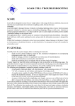
1
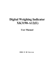
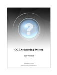
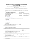
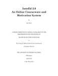
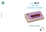
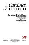
Load Cell Approvals LC_Compatibility Worksheet instructions Load Cell Compatibility Worksheet User’s Guide Ver 1.00 (01 Jan 2011) The Excel Worksheet Template LC_Compatibility.xlt has been prepared to assist the user in ensuring that a device meets the Measurement Canada guidelines for use of appropriate Approved Load Cells. Approved Load Cells are only mandatory in those devices where the requirement is noted in the Notice of Approval (NOA). The use of Approved and compatible load cells is recommended in all devices. Use of the worksheets (electronic or manual) is not mandatory but is recommended to ensure the selected load cell is suitable for use in the device. Completion of the worksheet will prove that all requirements have been met. It is further recommended that a copy of the worksheet be kept on file for each scale configuration. Use of the Template To use the worksheet template1, you must be running Microsoft Excel ver. 2003 SP3 or later on a PC2. Some features may not be supported by previous versions of the application. The manual worksheet may be used instead of the electronic version, but care must be taken to ensure the calculations are completed properly. Additional copies of the template and/or the worksheets may be obtained directly from Measurement Canada. The template (XLT file) should be installed in your Microsoft Excel Template folder. The template is then selected through the Excel File->New menu. The available templates will be displayed and the appropriate one may be chosen. In this way, you will not have to worry about corrupting the original template and the automated features will work as expected. Occasionally, security settings may prevent the application from running properly. If prompted, please allow the application to run on your system. Security settings may be changed in Excel 2003 through the Tools->Macro->Security->Security Level tab. Choosing Medium Security will prompt you to allow the application to run. Default template folder Windows XP drive:\Documents and Settings\ [user name] \Application Data\Microsoft\Templates\ Default template folder Windows Vista and Windows 7 drive:\Users\ [user name] \AppData\Roaming\Microsoft\Templates\ The user should always ensure that they are using the latest version of the template that is available from Measurement Canada. 1 Although you may use the Worksheet (XLS), use of the Template (XLT) is preferred. Properly using a template file will ensure that you never inadvertently corrupt the master template file. 2 The template has not been tested on an Apple (Mac) Computer. Measurement Canada Page -1- 01 Jan 2011 Load Cell Approvals LC_Compatibility Worksheet instructions Icons Translate Delete Print Info Language The language of the template may be toggled using the translate button at the top left of the data entry screen. The language may also be toggled from the Automatic or Manual worksheets by selecting the translate button within these screens. Tip: Select your language of choice and then resave the Template. The selected language will now be the default each time you use the template. Tip: Set default parameters as appropriate and then resave the Template. These parameter values will now be the default each time you use the template. Tip: Parameters which have been grayed out on the Data Entry Screen are non mandatory. Printing & QuickPrint Selecting either of the two PRINT icons will allow you to print a hard copy of the data. There is an option on the Data Worksheet called QuickPrint. Selecting QuickPrint will automatically send any print requests to the default printer without any further user intervention. By unselecting QuickPrint, you will be prompted to first select the printer you wish to use, you will then be shown a Print Preview of your print job. This option allows you to customize your print jobs. The first PRINT icon is in the Automatic Worksheet. If QuickPrint is selected, then both the Data and the Automatic worksheets will be printed if you select this icon. If QuickPrint is not selected, you will be given the option of printing both the Automatic Worksheet and the Data Sheet or the Worksheet only. The second PRINT icon is in the Manual Worksheet. Selecting this icon will print only the Manual Worksheet. Measurement Canada Page -2- 01 Jan 2011 Load Cell Approvals LC_Compatibility Worksheet instructions Other Features Info Your Data screen may include an Info button. Selecting this button will bring up a screen with user and application information. This information may be useful to Measurement Canada when attempting to troubleshoot an issue with the worksheet. Also on this screen may be an eMail button. Selecting this button will email the worksheet to Measurement Canada for review. This should be selected only if you are encountering an issue with the worksheet. Many email systems will not allow automated emails without confirmation from the user. If presented with a warning from your computer, you must agree to allow the email to proceed or it will be discarded before being sent. All emails currently go to [email protected]. Please ensure that a follow up email is sent explaining the issue being encountered. Default Data There is a checkbox entitled Default Data on your worksheet. This checkbox is used to determine if the Delete function will clear all user data from the worksheet or if it will restore default data in the user fields. At this time, this feature is not user selectable and the Delete function will reset default data in all user fields. Maximize Window There is a checkbox entitled Maximize on your worksheet. This checkbox will determine if the worksheet window is automatically maximized (full screen) on start up or if it remains in the default Window state. Date The worksheets now include a Date field. This field is automatically set when the worksheet is first saved and cannot be changed. This feature will only work as expected if the application is being used as a Template (recommended). Client ID/Scale ID Values entered on the first line of the Client ID and Scale ID user boxes will be carried over to the Automatic Worksheet. This data will appear immediately below the worksheet title. This information will assist in identification of the Automatic Worksheets and will be most useful for printed copies. Measurement Canada Page -3- 01 Jan 2011 Load Cell Approvals LC_Compatibility Worksheet instructions User Fields Both the Automatic and Manual worksheets contain a user field directly below section 10. These allow the user to make necessary notes and comments pertinent to the worksheet. The user fields for the Automatic Worksheet are identified with the symbol ►. These fields will be completed from the corresponding Note fields (part F) from the Data Worksheet. Screens The template contains three user screens. These are referred to as Data, Automatic and Manual. The names are located in the Worksheet Tabs. If you see additional Tabs, then you have an unprotected worksheet that may not operate as expected. Please contact Measurement Canada for an updated copy. Each of the three screens may be chosen by clicking on the applicable tab. The screens may also be selected using the keyboard by pressing Ctrl-Shift PgUp/PgDn. (Please note that due to a quirk in some versions of Excel, this will not work to navigate away from the DATA worksheet. It is recommended that you simply select the appropriate tab with your mouse). Data Entry Screen The first is the Data Entry Screen and is the only screen that the user needs to access to enter data. All data entered in this screen will be reflected as results in the Automatic screen. There is some simple data checking in this screen. If you enter an invalid response in a cell you may get an error message or the data may turn red. Either of these indicates a problem. Please note that not all parameters are being error checked. It is up to the user to ensure that valid data is entered into the appropriate field. Refer to the Parameters section below for a more detailed discussion regarding how to fill out the Data fields. Automatic Worksheet Screen The second screen is the Automatic Worksheet and is intended as output only. The data entered into the Data screen is used to complete the outputs in this screen. In this view, you will be able to see at a glance whether or not the load cell parameters match up correctly with the indicating and weighing elements. A PASS/FAIL/WARNING results field is shown in green/red/amber respectively. If all the results fields show Green/Pass then the cell is acceptable for use in the device. If any of the fields are Red/Fail then there is a problem that must be addressed in the Data screen. Amber/Warning in the results field indicates an undesirable situation but not necessarily one that would result in the chosen load cell being unsuitable for the application. This will sometimes happen when Measurement Canada Page -4- 01 Jan 2011 Load Cell Approvals LC_Compatibility Worksheet instructions data for parameters not monitored by Measurement Canada fall outside of the recommended ranges. While you need not correct a Warning, it is recommended that you investigate why the parameter did not Pass. Manual Worksheet Screen The third screen is a copy of the Manual Worksheet and is intended to allow the user to print out copies of the worksheet to be completed manually. Although data may be entered into this screen, the screen is not live and no automatic calculations will take place. It is up to the user to make the calculations manually. It is recommended that you use the Automatic sheet whenever possible to ensure accurate calculations. In all cases, each shaded field must be completed as appropriate. Care must be taken, especially with the Manual Worksheet to ensure that the correct fields are completed when selecting Single Range, Multiple Range or Multi-Interval as the appropriate fields are selectively shaded depending upon the settings in the Data Entry Screen. First Run Disclaimer The first time the worksheet is run, the user will have to accept a disclaimer. This disclaimer is to ensure the user understands that use of the worksheet is accepted at the user’s own risk. You must accept this or the worksheet will be disabled. 1. The Automated Worksheet is being provided solely for informational purposes and is not intended to provide specific advice or recommendations in any circumstances. Measurement Canada does not retain any of the data entered into the Worksheet, and all data remains on the user's computer. Users assume the risk associated with the use of this site and with the use of their own computers. The Pass/Fail determination is based on the information provided by the user; therefore it may only be relied upon if the information has been accurately entered. La feuille de calcul automatisée est fournie à des fins informatives seulement et ne vise pas à formuler de conseils ni de recommandations. Mesures Canada ne conserve aucune donnée consignée dans la feuille de calcul; toutes les données demeurent dans le système de l’utilisateur. Les utilisateurs acceptent les risques liés à l’utilisation du présent site et de leur propre système. La détermination de l’acceptation ou du rejet est fondée sur les renseignements fournis par l’utilisateur. Par conséquent, ils ne sont fiables que lorsque l’information consignée est exacte. 2. Her Majesty assumes no responsibility for any errors, omissions, or misleading statements obtained through the use of the Automated Worksheet. The data, information or results obtained through the use of the Worksheet have no legal authority. Her Majesty makes no guarantees, representations, or warranties respecting the Worksheet, either express or implied, arising by law or otherwise, including but not limited to, effectiveness, completeness or accuracy, or fitness for a particular purpose. Measurement Canada Page -5- 01 Jan 2011 Load Cell Approvals LC_Compatibility Worksheet instructions Sa Majesté n’est aucunement responsable des erreurs, des omissions ou des énoncés trompeurs découlant de l’utilisation de la feuille de calcul automatisée. Les données, les renseignements ou les résultats obtenus lors de l’utilisation de la feuille de calcul n’ont aucun pouvoir légal. Sa Majesté ne formule aucune garantie ni réclamation relativement à la feuille de calcul, qu’elle soit expresse ou implicite, découlant des lois ou autrement, notamment quant à l’efficacité, à l’intégralité, à l’exactitude ou au caractère approprié de la feuille de calcul dans un but particulier. 3. Her Majesty shall not be liable in respect of any claim, demand or action alleging any loss, injury or damages, direct or indirect, which may be attributable to the reliance on and use of the Automated Worksheet. Sa Majesté n’engage nullement sa responsabilité à l’égard de toute réclamation, revendication ou poursuite qui se fonde sur une perte, des blessures ou des dommages, directs ou indirects, pouvant découler du fait que l’utilisateur a utilisé la feuille de calcul automatisée ou s’y est fié. Measurement Canada Page -6- 01 Jan 2011 Load Cell Approvals LC_Compatibility Worksheet instructions Parameters A. Weighing or Load Receiving Element (LRE) 1. Accuracy Class. Enter the Accuracy Class for the Weighing Element. This must be a NAWDS approved Class and should be taken from the NOA when possible. The Class entered in this field must reflect the device configuration. Entering any other Class in this field is not acceptable. In order to ensure data integrity, the device Class should be selected from the drop down list. 2. Maximum Capacity (Max). Enter the Max or capacity of the device as configured. In the case of a multiple range or multi-interval device, the Max for largest range or interval shall be entered in this field. Units. Select the appropriate units (kg or lb) for the data. The units used here must be used throughout the rest of the sheet when entering mass. You will have to select the units for Max. All other units will be updated according to the units selected. All data must be entered in the appropriate units for the sheet to function correctly. 3. Verification Scale Interval (e). Enter the interval size of the device as configured. Interval size must be entered in the same units as Max. In the case of a multiple range or multi-interval device, the e for largest range or interval shall be entered in this field. 4. Number of Load Cells (N). Enter the number of load cells used in the load receiving element (LRE). If two or more LREs are used together, each should be evaluated separately. Most electro-mechanical conversions use a single load cell. In all cases there must be at least 1 load cell entered for the sheet to function correctly. 5. Reduction Ratio (R). Reduction Ratio is 1 for full electronic devices with no levers. If there are levers, then the reduction ration must be calculated. The proper calculation is: Reduction ratio = [(force on load cell) / (force on LRE)] = [1 / (scale multiple)] Note: Reduction Ratio is the inverse of the Scale Multiple. 6. Deadload (DL). Enter the weight of the LRE. You must use the same units as used for Max above. 7. Initial Zero Setting Range (IZSR). You must calculate the range that the IZSR will function over and enter this value here. The entry must be in terms of mass, Measurement Canada Page -7- 01 Jan 2011 Load Cell Approvals LC_Compatibility Worksheet instructions not percentage. This is the maximum amount of Initial Zero the device is capable of applying. 8. Non-Uniform Distribution Factor (NUD %). NUD is a factor, in percentage, used to increase the required capacity of the load cells to account for such things as off center loading. . This factor is to be determined by the scale manufacturer and may be assumed to be zero (0) if appropriate. The following values are recommended but not mandatory: a. 0% Max for devices with lever work and one load cell, or with load receivers which allow for only minimal eccentric loading (hopper or tank) or with one single point load cell. b. 20% Max for other conventional weighing devices c. 50% Max for On-Board weighing devices, overhead rail scales, etc. d. 50% Max for multi-platform weighing devices. This value is to be determined by the scale company responsible for configuring the device. The value may be set to zero (0) if it is not required. 9. Non-Uniform Distribution Factor (NUD). This value is in terms of mass and is calculated as: Max x (NUD %) Do not enter a value in this field – it is calculated automatically. 10. Positive Additive Tare range (T+). Enter the maximum amount of Positive Tare the device is capable of applying to the weight display. Enter 0 if not applicable. This value is used to address the additional load placed upon the LRE when tare is in use. 11. Temperature Limits for the Weighing Element. This should be a range of -10 to +40 degrees Celsius unless otherwise stated in the NOA for the device. These values must be entered in degrees Celsius (°C). 12. Load Cell cable length (L). For now, this is a non-mandatory field. It is suggested that the length of the cable (in metres) supplied with the load cells be entered in this field. It is further recommended that the supplied load cell cables not be cut to suit the application. 13. Cross section of the wire in the load cell cable (A). For now, this is a nonmandatory field. It is suggested that the cross sectional area (in mm2) of one conductor within the load cell cable be entered in this field. This information is usually available on the LC certificate or from the table below. Measurement Canada Page -8- 01 Jan 2011 Load Cell Approvals LC_Compatibility Worksheet instructions AWG Ø inches Ø millimetres area mm2 10 0.1019 2.59 5.26 11 0.0907 2.30 4.17 12 0.0808 2.05 3.31 13 0.0720 1.83 2.63 14 0.0641 1.63 2.08 15 0.0571 1.45 1.65 16 0.0508 1.29 1.31 17 0.0453 1.15 1.04 18 0.0403 1.02 0.82 19 0.0359 0.91 0.65 20 0.0320 0.81 0.52 14. Fraction of the maximum permissible error (mpe) for the connecting elements (pcon). Unless otherwise specified in the NOA this value shall be 0.5. This field has been disabled in this version of the worksheet. 15. Number of Divisions (n). This is a calculated field and must not be changed. n = Max / e B. Indicator (Ind) 1. Accuracy Class. Enter the Accuracy Class for the Indicating Element. This must be a NAWDS approved Class and should be taken from the NOA when possible. The Class entered in this field must reflect the device configuration. Entering any other Class in this field is not acceptable. 2. Maximum Number of scale intervals (nind). Enter the maximum number of intervals that the indicating element has been approved for. This information shall Measurement Canada Page -9- 01 Jan 2011 Load Cell Approvals LC_Compatibility Worksheet instructions be taken from the NOA when possible. The number must also be within acceptable range for the device Class chosen. 3. Load cell excitation voltage (Uexc). Enter the actual or nominal load cell excitation voltage being provided by the indicating element. This value must be within range for the chosen load cell. This information should be available from the indicating element manufacturer. Must be entered in volts (v). 4. Minimum Input Voltage (Umin). This is the minimum acceptable input signal voltage of the indicating element. This information should be available from the indicating element manufacturer. Must be entered in millivolts (mV). 5. Minimum Input voltage for a single scale interval (ΔUmin). Enter the minimum acceptable voltage required by the indicating element to resolve a single scale interval. This information should be available from the indicating element manufacturer. Must be entered in microvolts (µV). 6. Minimum Load Cell impedance (RLmin). For now, this is a non-mandatory field. Enter the lowest load cell impedance that the indicating element is capable of driving. Must be entered in ohms (Ω). 7. Maximum Load Cell impedance (RLmax). For now, this is a non-mandatory field. Enter the highest load cell impedance that the indicating element is capable of driving. Must be entered in ohms (Ω). 8. Temperature Limits for the Indicating Element. This should be a range of -10 to +40 degrees Celsius unless otherwise stated in the NOA for the device. These values must be entered in degrees Celsius (°C). 9. Fraction of the maximum permissible error (mpe) for the indicating elements (pind). Unless otherwise specified in the NOA this value shall be 0.7. This field has been disabled in this version of the worksheet. 10. LC Cable connection. For now, this is a non-mandatory field. This value must be either 4 or 6 wires. Enter 4 if there are no sense lines, if the sense lines are tied to the excitation lines at the indicator or if the sense lines are simply not being used. 6 should only be entered when the sense lines are taken all the way back to the load cells. 6 wire installations are recommended. 11. Maximum load cell cable length / wire cross section [(L/A)max]. For now, this is a non-mandatory field. This value may be obtained from the indicating element manufacturer. Measurement Canada Page -10- 01 Jan 2011 Load Cell Approvals LC_Compatibility Worksheet instructions C. Configuration Single Range – automatically entered for single range device. Multiple Range or Multi-Interval Device 1. 1st range or interval – required for multiple range or multi-interval device. This value must equal Max & e of the 1st or smallest range or interval and be entered in the same units as Max of the device. 2. 2nd range or interval – required for multiple range or multi-interval device. This value must equal Max & e of the 2nd or mid range or interval and be entered in the same units as Max of the device. 3. 3rd range or interval – required for multiple range or multi-interval device. This value must equal Max & e of the 3rd or largest range or interval and be entered in the same units as Max of the device. This worksheet is only capable of dealing with a maximum of three ranges or intervals. If more are required, please contact your Regional Gravimetric Specialists for more information. D. Load Cell(s) 1. Accuracy Class. Enter the Accuracy Class for the load cell. This should be taken from the Notice of Approval (NTEP Certificate of Conformance or OIML Certificate of Conformity) when possible. Class may be OIML or NTEP. The rest of the parameters must be applicable to the Class of load cell chosen in this step. 2. Load Cell Maximum Capacity (Emax). Manufacturer’s rating for maximum load cell capacity. Must be entered in the same units as LRE Max above. 3. Load Cell Minimum Capacity (Emin). Manufacturer’s rating for minimum load cell capacity. This is the smallest load that may be applied to a load cell without exceeding the maximum permissible error (mpe) for the cell. The load cell is not designed to be used below this capacity and must be pre-loaded beyond this value in use. Must be entered in the same units as LRE Max above. This value may be equal to zero (0) in some cases. 4. Load Cell Safe Limit (lim). For now, this is a non-mandatory field. Manufacturer’s rating for maximum safe overload. This is the maximum load that may be applied to a load cell without causing a permanent degradation of the performance of that cell. This parameter is often expressed as a percentage of Emax and if so, it must be converted to and entered in the same units as LRE Max above. Measurement Canada Page -11- 01 Jan 2011 Load Cell Approvals LC_Compatibility Worksheet instructions 5. Temperature Limits for the Load Cell. This should be a range of -10 to +40 degrees Celsius unless otherwise stated in the NOA for the cell. These values must be entered in degrees Celsius (°C). 6. Rated Cell output in mV/V (C). Manufacturer’s rated load cell output in millivolt output (signal) per volt input (excitation). In the case of a multi-cell scale where the manufacturer supplies actual cell output for each cell, please enter the nominal cell output in this field. (e.g. actual cell output = 3.002, 3.000, 3.002, 3.001 ► enter 3.0 mV/V) 7. Number of Load Cell Intervals (nLC). Approved number of intervals for the load cell. This number will be available on the load cell certificate and must be appropriate for the Class of device being installed. OIML cells will often show this value in terms of 1000 intervals (e.g. a C3 load cell would be a Class C approved to 3000 intervals). 8. Minimum Load Cell verification interval (Vmin). Smallest approved load cell interval. This parameter will be listed on the cell certificate. Vmin may be different for OIML vs. NTEP cells and the appropriate value must be entered. 9. Y is a calculated value known as Relative Vmin . Y is the ratio of the Maximum Cell Capacity (Emax) to the Minimum Load Cell Verification Interval (Vmin). This ratio describes the resolution of the load cell independent from the load cell capacity. Y = Emax / Vmin Do not enter a value in this field. 10. Z is a calculated value known as Relative DeadLoad Output Return (DR). Z is the ratio of the Maximum Load Cell Capacity (Emax) to twice the Minimum Deadload Output Return. This ratio is used to describe multi-interval devices. Z may be assumed to be equal to nLC. Z = EMax / (2 X DR) ; or Z = nLC Do not enter a value in this field. 11. Input Resistance (RLC). For now, this is a non-mandatory field. This is a manufacturer specified parameter and may be found in the NOA for the load cell. 12. Fraction of the maximum permissible error (mpe) for the load cells (pLC). Unless otherwise specified in the NOA this value shall be 0.5. If changing this from the default value, you are advised to discuss the implications with your Gravimetric Measurement Canada Page -12- 01 Jan 2011 Load Cell Approvals LC_Compatibility Worksheet instructions Specialist. The total mpe for the system must fall within a range and this value may not be changed without adjusting the fraction of the mpe values for the other components comprising the system. This field has been disabled in this version of the worksheet. E. Miscellaneous None of these parameters are considered mandatory and the fields are provided simply to allow you to record the relevant information and to identify the load cell chosen. It is suggested that this information be made available in case there are questions as to which load cell was used for a given installation. F. Notes This section is provided for you to record any further information that you feel may be pertinent to the scale or the installation. There are several notes fields available for your own use. The template may contain standard notes which may be overwritten at will. Standard notes, if implemented, will reappear each time the template is loaded. This feature allows you to specify permanent notes for your own use. A couple of fields in the Notes areas may contain error checking formulas. It will not hurt to overwrite these formulas with your own notes, but the error checking will disappear. These formulas will be reinstated the next time a new template is loaded. The first two lines of the Notes fields have been identified with the symbol ►. These two lines will be automatically carried forward to the notes section at the bottom of the Automatic Worksheet. This allows the user to make annotations on the Automatic Worksheet and will be most useful when a hard copy of the worksheet has been printed. Measurement Canada Page -13- 01 Jan 2011 Load Cell Approvals LC_Compatibility Worksheet instructions Worksheets Use of the Automatic Worksheet is recommended. If using the automatic worksheet, each of these considerations will be addressed automatically. If using the manual worksheet, you must calculate each to ensure that the chosen parameters are acceptable for the device. In any case, the following will explain what calculations are being made to ensure compatibility. 1. Accuracy Class of the Load Cell (LC), Indicator (IND) and Weighing Element (WI). This section will ensure that the load cell, indicator and weighing element are all compatible. The load cell class and the indicator class must be at least the same as or better than the configured weighing element class. OIML load cell classifications are indicated by the letters A, B, C & D which are roughly equivalent to NAWDS Class I, II, III & IIII devices. Class IIIHD requires a Class III, IIIL or C load cell. 2. Temperature Limits of the Weighing Element (WI) compared with the temperature limits of the Load Cell (LC) and the Indicator (IND) in °C. The temperature limits of the load cell and the indictor must be at least as large as the temperature limits for the weighing element. In no case will a range be specified outside of -10 °C and + 40 °C. 3. Sum of the squares of the fractions pi of the maximum permissible errors for Load Cells, Indicator and Weighing Element. This item ensures that the error apportionment is distributed properly for the device. Currently, Measurement Canada allows 0.7 x LOE when evaluating each component of a device. This practice may be subject to change in the future in order to allow other error distributions. Until changes are implemented, only default values shall be used. The default values are: 0.25 (0.52) for the Weighing Element (pcon) 0.25 (0.52) for the Load Cell (pLC) 0.49 (0.72) for the Indicating Element (pind) The values for the weighing element and the load cell combined are equal to 0.5 (≈0.72) for the complete weighing element including load cells. If evaluated separately, the complete weighing element will be allotted 0.7 x LOE. Any manufacturer wishing to change the distribution of errors should discuss this with the mass approval laboratory or their local Gravimetric Specialist. 4. Maximum number of Verification Scale Intervals (e) of the Indicator and the Weighing Element. For each indicator, the maximum number of verification scale intervals, nind, shall not be less than the number of verification scale intervals, n, of the weighing element. Measurement Canada Page -14- 01 Jan 2011 Load Cell Approvals LC_Compatibility Worksheet instructions nind ≥ n For a multi-interval, or multiple range Indicating Element, this applies to any individual weighing range or partial weighing range. nind ≥ ni The automatic worksheet will change format to reflect single range, multiple range or multi-interval depending upon the device type selected in the check box on the first Data sheet. The manual worksheet always shows all fields, but the highlighted fields, which must be completed, will also change according to this selection. 5. Maximum Capacity of the load cells must be compatible with Max of the Indicator. This seems like a simple requirement, but the calculations are somewhat complex. In order to ensure that the load cell capacity (Emax) is suitable for use with the indicator we must calculate a correction factor (Q). Q is used to account for possible eccentric loading (NUD), dead load of the weighing element (DL), initial zero setting range (IZSR) and additive tare (T+). Q = (Max + DL + IZSR + NUD + T+) / Max Once this has been done, the maximum capacity of the load cell (Emax) must satisfy the condition: Emax ≥ Q x Max x R / N 6. a. Maximum number of Verification Scale Intervals of the Load Cell and the Indicator. The chosen load cell must be approved for no less than the number of verification scale intervals of the device as configured. nLC ≥ Max / e For a multi-interval, or multiple range Indicating Element, this applies to any individual weighing range or partial weighing range. nLC ≥ Maxi / ei b. Minimum Dead Load output return of the load cell and smallest verification scale interval of a multi-interval weighing device. On a MultiInterval device, the minimum dead load output return must be sufficient for each interval. This can be calculated using the variable Z and ensuring that Z is not less than Maxr / e1. Z = Emax / (2 x DR) Measurement Canada Page -15- 01 Jan 2011 Load Cell Approvals LC_Compatibility Worksheet instructions Z ≥ Maxr / e1 or nLC ≥ Maxr / e1 c. Minimum Dead Load output return of the load cell and smallest verification scale interval of a multiple range weighing device. On a Multiple Range device where the same load cells are used for more than one range, the minimum dead load output return of the load cell shall satisfy the equation: Z ≥ 0.4 x Maxr / e1 or nLC ≥ 0.4 x Maxr / e1 d. Actual dead load of the load receptor compared to the minimum dead load of the load cells (in kg). In order to ensure that the cells are only used within the acceptable range, we must ensure that the minimum dead load has been applied to the load cells. The following equation must be satisfied: DL x R / N ≥ Emin 7. Compatibility between Verification Scale Interval (e) of the Weighing Device and minimum Load Cell interval (in kg). The minimum load cell interval (Vmin) must be appropriate for the configured verification scale interval (e) of the device. Vmin = Emax / Y Vmin ≤ e x R / √N 8. Minimum signal input voltage for the Indicating Element (indicator) and minimum input voltage per Verification Scale Interval (e) compared to the actual output of the Load Cells. In order to ensure that the load cell is an electrical match to the indicator, the following equations shall be satisfied. U ≥ Umin ΔU ≥ ΔUmin The minimum input voltage for the indicator, U, with an unloaded weighing element is calculated as follows: U = C x Uexc x R x DL / (Emax x N) The signal per verification scale interval, ΔU, is calculated as follows: Measurement Canada Page -16- 01 Jan 2011 Load Cell Approvals LC_Compatibility Worksheet instructions u C R Uexc e E max N Uexc = load cell excitation voltage (V) (B.3) Umin = minimum signal input voltage for the indicator (mV) (B.4) ΔUmin = minimum signal input voltage per verification scale interval (µV) (B.5) UMRmin = measuring range minimum signal voltage (mV) ( UMRmax = measuring range maximum signal voltage (mV) Emax = load cell maximum capacity (D.2) C = rated load cell output in mV/V (D.6) e = verification scale interval (A.3) N = number of load cells (A.4) R = reduction ratio (A.5) 9. Minimum signal input voltage for the Indicating Element (indicator) and minimum input voltage per Verification Scale Interval (e) compared to the actual output of the Load Cells. The load cell impedance, RLC, should be matched to the indicator. This may be verified by ensuring that the resistance of the load cell / number of load cells in use falls within the rated impedance range as specified by the indictor manufacturer. RLmin ≤ RLC / N ≤ RLmax RLmin = minimum load cell impedance (Ω) RLmax = maximum load cell impedance (Ω) This parameter is not currently monitored by Measurement Canada. 10. Length of additional cable between Load Cells and Indicator per wire cross section in m/mm2. The length of additional cable between the load cell and the indicator should be accounted for. Additionally, load cell cable supplied with the approved load cell should not be cut to suit the installation. The resistance of the cable is integral to the calibration parameters of the load cell. The following equation should be satisfied: L/A ≤ (L/A)max This parameter is not currently monitored by Measurement Canada. Measurement Canada Page -17- 01 Jan 2011 Load Cell Approvals LC_Compatibility Worksheet instructions How to Read a Load Cell Measurement Canada has chosen to accept NTEP and OIML approved load cells. It is up to the scale manufacturer to decide which will be used. Once a selection is made, the parameters for that approval must be used. You cannot mix and match parameters between the two approvals. For purposes of ensuring that a load cell is suitable for use, the following are deemed to be equivalent. OIML Class A = NTEP Class I = suitable for use in MC NAWDS Class I devices. OIML Class B = NTEP Class II = suitable for use in MC NAWDS Class II devices. OIML Class C = NTEP Class III/IIIL = suitable for use in MC NAWDS Class III/IIIHD devices. OIML Class D = NTEP Class IIII = suitable for use in MC NAWDS Class IIII devices. Some manufacturers may use other Class designators. These are intended for nontrade applications only. Certain parameters will not be monitored by Measurement Canada, however it is suggested that OIML & NTEP requirements for selecting suitable load cells be followed whenever possible. These non-monitored items include cable length, area and resistance, OIML condensating classifications and NTEP S & M designations. OIML A B NTEP I II C III D IIIL IIII 3 4 MC NAWDS I II II (e≥0.1g) III III (e≥5g) IIIHD IIII Min / Max (e) 50 000 / ∞ 100 / 100 000 5 000 / 100 000 100 / 10 000 500 / 10 000 2 000 / 10 0003 100 / 1 0004 Class IIIHD should be limited to 10 000 divisions to comply with load cell restrictions. Class IIII should be limited to 1 000 divisions to comply with load cell restrictions. Measurement Canada Page -18- 01 Jan 2011 Load Cell Approvals LC_Compatibility Worksheet instructions OIML Load Cell http://oiml.org/certificates/ Measurement Canada will make no distinction between NH - No Humidity testing, CH Condensating Humidity testing, or SH – Static Temperature Humidity testing. In the absence of marking on an OIML approved cell, CH may be assumed. OIML Load cells must have been approved under the R60 Mutual Acceptance Arrangement. These can be identified by the OIML logo with the stylized letters MAA as depicted above (either on the cell or the accompanying certificate). The remaining required information should be available on the Certificate that accompanies the load cell. Search OIML Certificates of Conformity at: http://oiml.org/certificates/ Measurement Canada Page -19- 01 Jan 2011 Load Cell Approvals LC_Compatibility Worksheet instructions NTEP Load Cell http://www.ncwm.net/content/ntep NTEP Load Cells will generally have the required information spelled out on the cell and/or in the accompanying certificate and documentation. The NTEP cells will have a further marking of S for Single Cell applications and M for Multiple Cell applications. NTEP allows S marked cells to be used in any application, while M marked cells may only be used in multiple cell applications. Measurement Canada will make no distinction between S and M marked load cells. Manufacturer: Fictitious Scale Company Model: 123ABC S/N: 1234567890-100 Certificate: 100-1 Class: III n = 10 000 Cap: 50K at 3.0491 mv/V S/N: 1234567890 Capacity is shown as 50 000 lbs and represents Emax. Care must be taken to ensure that the correct units (lb or kg) are used. The rated Cell Output (C) is 3.0491 mv/V. In this case, the actual value is indicated and may be used in the worksheet. In many cases, the nominal value (3 mv/V) may be all that is indicated. In the case of multiple load cells, the nominal value may have to be chosen. The remaining required information should be available on the Certificate that accompanies the load cell. Search NTEP Certificates of Conformance at: http://www.ncwm.net/ntep/index.cfm?fuseaction=search Measurement Canada Page -20- 01 Jan 2011 Load Cell Approvals LC_Compatibility Worksheet instructions Use of the Worksheet Any questions or concerns with the manual worksheet or the Excel template should be directed to your Regional Gravimetric Specialist for resolution. Luciano Burtini Senior Program Officer - Gravimetric | Agent de programme principal - Gravimetric Program Development Directorate | Développement de programme Measurement Canada | Mesures Canada Industry Canada | Industrie Canada 151 Tunney's Pasture Driveway | 151, allée du parc Tunney Ottawa ON K1A 0C9 email | courriel [email protected] Telephone | Téléphone 250-862-6557 Facsimile | Télécopieur 250-712-4215 Teletypewriter | Téléimprimeur 866-694-8389 Government of Canada | Gouvernement du Canada Measurement Canada Page -21- 01 Jan 2011