1
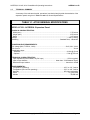
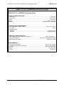
TM
ACCESS/A
EXPANSION PANEL
MODELS: A710X & A711X
Installation and
Operating Instructions
TiL Document No.
06RE387 rev-A
April 2007
Technisonic Industries Limited
240 Traders Blvd. E., Mississauga, Ontario L4Z 1W7 Tel:(905)890-2113 Fax:(905)890-5338
www.til.ca
ACCESS/A A710X/A711X Installation & Operating Instructions
06RE387 rev. B
REVISIONS
Revision
Page
A
1-2
B
iii
Description
Date
Approved
compliance reference changed
from TSO-C50c to TSO-C139
Jun 21 2007
RKD
Added TSO installation notification
Nov. 11/10
Technisonic Industries ltd.
Copyright 2007 BY TiL
ALL RIGHTS RESERVED
RD
ii
ACCESS/A A710X/A711X Installation & Operating Instructions
06RE387 rev. B
WARRANTY INFORMATION
The Models A710X and A711X Audio Expansion Panels are under warranty for one year from date of
purchase. Failed units caused by defective parts or workmanship should be returned for warranty
service to:
Technisonic Industries Limited
240 Traders Blvd. E.,
Mississauga, Ontario L4Z 1W7
Technisonic Industries Limited
3840 East Robinson Road, Suite 214
Amherst, New York 14228
Tel: (905) 890-2113
Fax: (905) 890-5338
Tel: (716) 691-0669
TRADEMARK INFORMATION
ACCESS/A, ACCESS/D, ACCESS/R & ACCESS/F are all trademarks of Technisonic Industries Ltd. and
Sphere Research Corporation. All rights reserved.
TSO INSTALLATION NOTIFICATION
The conditions and tests required for TSO approval of this article are minimum performance standards.
It is the responsibility or those installing this article either on or within a specific type or class of aircraft to
determine that the aircraft installation conditions are within TSO standards. TSO articles must have
separate approval for installation in an aircraft. The article may be installed only if performed under
14CFR part 43 or the applicable airworthiness requirements.
Technisonic Industries ltd.
Copyright 2007 BY TiL
ALL RIGHTS RESERVED
iii
ACCESS/A A710X/A711X Installation & Operating Instructions
06RE387 rev. B
TABLE OF CONTENTS
SECTION 1
GENERAL DESCRIPTION
1.1
1.2
1.3
1.4
1.5
1.6
Introduction ................................................................................................................1-1
Description .................................................................................................................1-1
Purpose of Equipment ...............................................................................................1-2
Model Variation ..........................................................................................................1-2
Technical Summary ...................................................................................................1-5
System Limitations .....................................................................................................1-7
SECTION 2
INSTALLATION INSTRUCTIONS
2.1
2.2
2.3
2.4
2.5
2.6
2.7
2.8
2.9
2.10
2.11
General ......................................................................................................................2-1
Equipment Packaging Log .........................................................................................2-1
Wiring Requirements .................................................................................................2-1
Expansion Panel Installation & Drawings ..................................................................2-1
Cable Clearance ...............................................................................................2-2
Panel Modifications ..........................................................................................2-2
Shield Grounds .................................................................................................2-2
Internal Options ................................................................................................2-2
Installation Kit Contents .............................................................................................2-8
Pin Locations and Connections .................................................................................2-9
Main Power ..............................................................................................................2-11
Backlighting Power ..................................................................................................2-11
Ground .....................................................................................................................2-11
Storage ....................................................................................................................2-11
Post Installation Adjustments.....................................................................................2-11
SECTION 3
OPERATION
3.1
3.1.1
3.1.2
3.1.3
3.2
3.2.1
3.3
Front Panel Operator’s Switches & Controls .............................................................3-1
RX or Receive Selectors .................................................................................3-2
TX or Transceiver Selectors ...........................................................................3-2
A711X RX Monitor Level Controls ..................................................................3-3
Special Signal Considerations ...................................................................................3-4
Sum Node .......................................................................................................3-4
Changing Overlay Lighting & Radio Legends ............................................................3-5
Technisonic Industries ltd.
Copyright 2007 BY TiL
ALL RIGHTS RESERVED
iv
ACCESS/A A710X/A711X Installation & Operating Instructions
06RE387 rev. B
LIST OF TABLES
1-1
1-2
A710X General Specifications ........................................................................................ 1-5
A711X General Specifications ........................................................................................ 1-6
LIST OF ILLUSTRATIONS
1-1
1-2
2-1A
2-1B
2-2
2-3
2-4
3-1
3-2
3-3
3-4
3-5
A710X Expansion Panel - General View ....................................................................... 1-3
A711X Expansion Panel - General View ....................................................................... 1-4
A710X Outline Drawing .................................................................................................. 2-3
A711X Outline Drawing .................................................................................................. 2-4
System Installation Drawings- COM11 – COM14 Wiring .............................................. 2-5
System Installation Drawings- COM15 – COM14 Wiring .............................................. 2-6
System Installation Drawings- Power & System Interconnect Wiring ........................... 2-7
Front Panel Operators Switches and Controls .............................................................. 3-1
RX & TX Selectors .......................................................................................................... 3-2
A711X RX Monitor Level Controls ................................................................................. 3-3
Overlay & Legend Insert ................................................................................................. 3-5
Removing the Entire Overlay Assembly ........................................................................ 3-5
Technisonic Industries ltd.
Copyright 2007 BY TiL
ALL RIGHTS RESERVED
v
ACCESS/A A710X / A711X Installation & Operating Instructions
06RE387 rev. B
SECTION 1
GENERAL DESCRIPTION
1.1
INTRODUCTION
This publication provides operating and installation information on the Model A710X and A711X,
ACCESS/A Audio Expansion Panels manufactured by Technisonic Industries Limited. These
units are designed to provide six additional communications channels to either the Model A710
or A711 ACCESS/A audio controllers. The A710X unit may be directly interchanged with an
A711X in the same harness, but the units are physically different in size, and the A711X has
individual volume controls for the receiver monitor levels.
1.2
DESCRIPTION
The A710X and A711X Audio Expansion Panels are designed to provide additional
communications channels to an existing ACCESS/A A710 or A711 Audio Controller. Seven
transceivers can be connected to the expansion panel and selected in the same manner as a
standard A710 or A711 audio controller.
The Expansion Panel is connected to an A710 or A711 controller via one of its com channels;
typically in the COM-7 position. This will reduce the maximum number of transceivers that an
A710 or A711 can directly access from seven to six.
Push-button transmit selector switches allow immediate selection of any of the seven supported
aircraft communications transceivers or PA amplifiers, while additional push-button audio input
selector switches allow receive monitoring of any or all of the supported transceivers.
Both the A711X and A710X route audio internally through passive components and are not
dependant on aircraft system power. A dedicated Emergency Switch is therefore not required
and thus is not incorporated within these units. If power is lost to the Expansion Panel it will
continue to function normally but with the following exception. The front panel status LEDs and
backlighting will not be functioning.
Technisonic Industries ltd.
Copyright 2007 BY TiL
ALL RIGHTS RESERVED
Page 1-1
ACCESS/A A710X / A711X Installation & Operating Instructions
1.3
06RE387 rev. B
PURPOSE OF THE EQUIPMENT
The A710 and A711 ACCESS/A Audio Controllers are able to directly access a maximum of
seven transceivers. Connecting an A710X or A711X Expansion Panel to the ACCESS/A
controller will increase this capability to a maximum of thirteen transceivers.
These units have been packaged to minimize size and weight characteristics and are ideally
suited for helicopter installations, or any other Dzus rail panel location. Both the A710X and
A711X meet all of the current requirements of US Forest Service "contractor furnished avionics"
and can be used in a dual control installation in conjunction with a TiL FM airborne transceiver to
comply with all US Forest Service Contract Requirements. The A710X and A711X are compliant
with TSO-C139. The units meet RTCA/DO-214 and RTCA/DO-160C applicable categories with
the exception of the RF Susceptibility Test, which is based upon the requirements of RTCA/DO160A, and the Lightning Induced Transient Susceptibility Test which is not called out under
RTCA/DO-170.
1.4
MODEL VARIATION
The A710 and A711 come in two basic lighting configurations. A +28VDC panel lighting version
and a +5VDC panel lighting version. Operationally the two are identical. The color of the solidstate backlighting is green-yellow, at approximately 565nm wavelength. Panel front color is matte
black. The default configuration is with 28VDC backlighting. See the ACCESS/A price list for
model numbers and availability or different versions. The most common variations are
summarized below:
A710X = 061248 - (dash number)
A711X = 061249 - (dash number)
Dash Numbers:
-2
-4
Black Panel
Black Panel
special order:
-6
Black Panel
-8
Black Panel
Technisonic Industries ltd.
28VDC Lighting
5VDC Lighting
28VDC Lighting, Night Vision
5VDC Lighting, Night Vision
Copyright 2007 BY TiL
ALL RIGHTS RESERVED
Page 1-2
ACCESS/A A710X / A711X Installation & Operating Instructions
06RE387 rev. B
FIGURE 1-1 A710X ACCESS/A EXPANSION PANEL - GENERAL VIEW
Technisonic Industries ltd.
Copyright 2007 BY TiL
ALL RIGHTS RESERVED
Page 1-3
ACCESS/A A710X / A711X Installation & Operating Instructions
06RE387 rev. B
FIGURE 1-2 A711X ACCESS/A EXPANSION PANEL - GENERAL VIEW
Technisonic Industries ltd.
Copyright 2007 BY TiL
ALL RIGHTS RESERVED
Page 1-4
ACCESS/A A710X / A711X Installation & Operating Instructions
1.5
06RE387 rev. B
TECHNICAL SUMMARY
A summary of the relevant electrical, operational, mechanical and physical characteristics of the
expansion panels are given in Table 1-1 and 1-2, General Specifications.
TABLE 1-1 A710X GENERAL SPECIFICATIONS
MODEL A710X - ACCESS/A Expansion Panel:
PHYSICAL CHARACTERISTICS:
Width (max.) ...................................................................................................................... 5.75 inches
Height (max.) .................................................................................................................. 1.875 inches
Depth ................................................................................................................................. 6.07 inches
Weight .......................................................................................................................... 1.4lbs. (0.64Kg)
Mounting .................................................................................................... Standard Dzus, 4 fasteners
POWER SOURCE REQUIREMENTS:
DC Voltage (MIN, TYPICAL, MAX) ........................................................................ 20.0V, 28 V, 32.2V
DC Current ................................................................................................................................ 20 mA
Backlighting Input:
Standard ................................................................................................................. 28 Vdc @ 50 mA
Optional .................................................................................................................. 5 Vdc @ 270 mA
TECHNICAL CHARACTERISTICS:
Input Impedance (Normal Mode, any RX input) .......................................................1.55 k Ω (typical)
Input to Input isolation .................................................................. better than -70 dB between inputs
Deselected input isolation ...................................................................................... better than -65 dB
ENVIRONMENTAL:
Temperature (operating) .................................................................................... -45°C to +70° Celsius
Temperature (survival non-operating) ............................................................... -55°C to +85° Celsius
Humidity ............................................................................................................ 95% Non-condensing
Shock ........................................................................................................................... 12 g (any axis)
Altitude ...............................................................................................................................25,000 feet
Technisonic Industries ltd.
Copyright 2007 BY TiL
ALL RIGHTS RESERVED
Page 1-5
ACCESS/A A710X / A711X Installation & Operating Instructions
06RE387 rev. B
TABLE 1-2 A711X GENERAL SPECIFICATIONS
MODEL A711X - ACCESS/A Expansion Panel:
PHYSICAL CHARACTERISTICS:
Width (max.) ...................................................................................................................... 5.75 inches
Height (max.) .................................................................................................................. 2.625 inches
Depth ................................................................................................................................ 6.07 inches
Weight ....................................................................................................................... 2.0 lbs. (0.91 Kg)
Mounting .................................................................................................... Standard Dzus, 4 fasteners
POWER SOURCE REQUIREMENTS:
DC Voltage (MIN, TYPICAL, MAX) ....................................................................... 20.0V, 28 V, 32.2V
DC Current ............................................................................................................................... 20 mA
Backlighting Input:
Standard ................................................................................................................. 28 Vdc @ 70 mA
Optional .................................................................................................................. 5 Vdc @ 370 mA
TECHNICAL CHARACTERISTICS:
Input Impedance (Normal Mode, any RX input) ................................................1.5K - 2K Ω (approx.)
Input to Input isolation .................................................................. better than -70 dB between inputs
Deselected input isolation ...................................................................................... better than -65 dB
ENVIRONMENTAL:
Temperature (operating) .................................................................................. -45°C to +70° Celsius
Temperature (survival non-operating) ............................................................. -55°C to +85° Celsius
Humidity ............................................................................................................ 95% Non-condensing
Shock ........................................................................................................................... 12 g (any axis)
Altitude ...............................................................................................................................25,000 feet
Technisonic Industries ltd.
Copyright 2007 BY TiL
ALL RIGHTS RESERVED
Page 1-6
ACCESS/A A710X / A711X Installation & Operating Instructions
1.6
06RE387 rev. B
SYSTEM LIMITATIONS
A summary of the relevant system limitations is given below.
Induced Signal Susceptibility, RF Susceptibility and RF Emission
The wiring connections called out in the Installation and Operating Instructions, chapter 2,
describes shield terminations for minimum ground loop noise. The test harnesses used for
RTCA/DO-160 sections 19, 20, and 21 – Induced Signal Susceptibility, RF Susceptibility, and
Emission of RF Energy respectively - used shield terminations at both ends of the cable. Should
RF susceptibility pose a problem in a particular installation the installer may wish to try
terminating shields at both ends of the cable, further, if this does not produce satisfactory results
then double shielding may be required.
Technisonic Industries ltd.
Copyright 2007 BY TiL
ALL RIGHTS RESERVED
Page 1-7
ACCESS/A A710X / A711X Installation & Operating Instructions
06RE387 rev. B
SECTION 2
INSTALLATION INSTRUCTIONS
2.1
GENERAL
This section contains information and instructions for the correct installation of the A710X and
A711X, ACCESS/A Expansion Panels.
Make certain that the unit is correctly operating in accordance with the equipment user's
requirements and manufacturer’s specifications, prior to releasing the equipment for service.
2.2
EQUIPMENT PACKING LOG
Unpack the equipment and check for any damage that may have occurred during transit. Save
the original shipping container for returns due to damage or warranty claims. Check that each
item on the packing slip has been shipped in the container. Verify that the equipment's
backlighting configuration is the same as that required.
2.3
WIRING REQUIREMENTS
Airframe wiring should be single conductor in accordance with MIL-W-22759 or multi-conductor in
accordance with MIL-C-27500 or Raychem 44 (81044) or 55 single or multi-conductor and
shielded wire. Heatshrink solder sleeves (such as Raychem or equivalent) should be utilized for
shield termination.
All audio input and output line connections should be made with 2 conductor/twisted pair shielded
cables as illustrated. The power and ground lines should be a minimum of #24 AWG (#22
preferred). Keying lines may be #24 AWG or larger.
CAUTIONS:
DO NOT bundle any low level audio lines with RF coaxial cables, 60 Hz or 400Hz AC
inverter, motor, pump or blower wiring, which can cause noise coupling between the various
systems, especially during RF transmission or pump/blower mechanical operation. Maintain as
much distance as possible from these types of wire bundles.
Note that there is really no effective field-installable shielding for magnetic coupling (which
occurs at high currents), and the only suitable prevention for this type of interference is distance
between the interfering lines. Shielded wiring is effective only for electrostatic coupling, or
voltage driven interference.
2.4
ACCESS/A EXPANSION PANEL INSTALLATION
The A710X and A711X ACCESS/A Audio Expansion Panels are designed to be Dzus mounted
and should be installed in conjunction with an IN-A710X installation connector kit. See Figure 21 for an outline drawing of the units with dimensions, to facilitate the installation.
Technisonic Industries ltd.
Copyright 2007 BY TiL
ALL RIGHTS RESERVED
Page 2-1
ACCESS/A A710X / A711X Installation & Operating Instructions
06RE387 rev. B
CABLE CLEARANCE:
Allow at least 2.5” of additional rear clearance for mating connectors and hoods (side routing),
or 3.0” (back routing). Cables should be long enough to permit the unit to be removed from the
panel, and the connectors to be easily disengaged. DO NOT dress or strap the mating cables so
that front removal is impossible, or the unit cannot be removed for service in the field.
PANEL MODIFICATIONS:
Modified panel legends, panel lighting, NVG compatibility, or overlay colors are also
possible, please see the price list for a full summary of options and part numbers. Overlays and
legends may be easily changed at low cost in the field with no special tools or service facilities
required.
SHIELD GROUNDS:
Convenient shield ground connections are provided at each connector for the indicated input
signal shield drains, and will give the shortest possible return for these lines. These shield lines
may be daisy chained together, and a single wire from each cable brought out to the connector
pin .
INTERNAL OPTIONS:
The A711X RX Monitor Level Controls have an adjustment range that normally go to
approximately 2-5% level at minimum setting (not off). This range can be reduced to zero by
installing optional internal jumpers.
The A710X does not have any configurable internal options.
DRAWINGS:
A full ACCESS/A Expansion Panel installation example is given in the multi-page sections of
Figure 2-x. These installation and mechanical drawings are available as AutoCAD files
(“DWG”/R12 format, Windows Metafile “WMF” or “DXF” format) free of charge to authorized TiL
dealers and completion centers.
Technisonic Industries ltd.
Copyright 2007 BY TiL
ALL RIGHTS RESERVED
Page 2-2
ACCESS/A A710X / A711X Installation & Operating Instructions
FIGURE 2-1A
Technisonic Industries ltd.
06RE387 rev. B
Outline Drawing for Model A710X ACCESS/A Expansion Panel
Copyright 2007 BY TiL
ALL RIGHTS RESERVED
Page 2-3
ACCESS/A A710X / A711X Installation & Operating Instructions
FIGURE 2-1B
Technisonic Industries ltd.
06RE387 rev. B
Outline Drawing for Model A711X ACCESS/A Expansion Panel
Copyright 2007 BY TiL
ALL RIGHTS RESERVED
Page 2-4
ACCESS/A A710X / A711X Installation & Operating Instructions
06RE387 rev. B
Shields are grounded as required at either end of the cables. Do not ground both ends of a shield.
Mic/Key/Lo lines may be run as a 3-cond. shielded wire in noisy environments for better RF rejection.
Figure 2-2 COM11 - COM14 WIRING
Technisonic Industries ltd.
Copyright 2007 BY TiL
ALL RIGHTS RESERVED
Page 2-5
ACCESS/A A710X / A711X Installation & Operating Instructions
06RE387 rev. B
Shields are grounded as required at either end of the cables. Do not ground both ends of a shield.
Mic/Key/Lo lines may be run as a 3-cond. shielded wire in noisy environments for better RF rejection.
Figure 2.3 COM15 – COM17 WIRING
Technisonic Industries ltd.
Copyright 2007 BY TiL
ALL RIGHTS RESERVED
Page 2-6
ACCESS/A A710X / A711X Installation & Operating Instructions
06RE387 rev. B
Shields are grounded as required at either end of the cables. Do not ground both ends of a shield.
Mic/Key/Lo lines may be run as a 3-cond. shielded wire in noisy environments for better RF rejection.
Figure 2-4 POWER & SYSTEM INTERCONNECT WIRING
Technisonic Industries ltd.
Copyright 2007 BY TiL
ALL RIGHTS RESERVED
Page 2-7
ACCESS/A A710X / A711X Installation & Operating Instructions
2.5
06RE387 rev. B
INSTALLATION KIT - CONTENTS
The IN-A710X installation kit (used for both A710X & A711X units) consists of:
1.
One 50 pin female D-subminiature mating connector complete with crimp
pins, V-locks and hood. (DD50S)
P101
Positronics p/n SD50F00JVLX + 50ea. FC7520D contacts
2.
One 37 pin female D-subminiature mating connector complete with crimp
pins, V-locks and hood. (DC37S)
P201
Positronics p/n SD37F00JVLX + 37ea. FC7520D contacts
Note: The mating connectors use a “one-hand”, tool-free Positronics V-lock assembly for ease of
airframe installation and removal.
.
In addition, the following items are packed with each A710X or A711X unit:
1.
This manual.
2.
Warranty registration card.
Technisonic Industries ltd.
Copyright 2007 BY TiL
ALL RIGHTS RESERVED
Page 2-8
ACCESS/A A710X / A711X Installation & Operating Instructions
2.6
06RE387 rev. B
INSTALLATION - PIN LOCATIONS AND CONNECTIONS
The pin numbers and locations for the connectors located on the rear of the A710X/A711X
ACCESS/A Expansion Panel are shown in the following tables.
Mating Cable Connector: DD50S
Bottom Connector J111 DD50P
(50 pin Female)
J111 Connector Pin Assignments – TX Connector
LOW
HIGH
17
34
1
2
3
Connection
Notes
+28VDC Power In
Power GROUND
Lighting/Dimmer Common (GND)
+5 VDC Dimmer Input
+28 VDC Dimmer Input
Main Power Input
Main Power Ground Line
Dimmer Lines
Dimmer Lines
Use only one
Dimmer Lines
Use only one
Connection
Notes
COM
MIC
KEY
42
25
8
COM-X In
To Audio Panel TX COM channel
50
49
48
47
46
45
44
33
32
31
30
29
28
27
16
15
14
13
12
11
10
COM 11 TX Mic Out
COM 12 TX Mic Out
COM 13 TX Mic Out
COM 14 TX Mic Out
COM 15 TX Mic Out
COM 16 TX Mic Out
COM 17 TX Mic Out
Left-hand-most TX switch
Right-hand-most TX switch
Shield Ground
43
The following pins are not used and should have no connection: 4-7, 9, 18-24, 26, 35-41.
View from solder side of DD50S MATING CONNECTOR:
1...................................17
18............................33
34.................................50
Technisonic Industries ltd.
Copyright 2007 BY TiL
ALL RIGHTS RESERVED
Page 2-9
ACCESS/A A710X / A711X Installation & Operating Instructions
06RE387 rev. B
Mating Cable Connector: DC37S
Top Connector J211 DC37P
(37 Pin Female)
J211 Connector Pin Assignments - RX Connector
LOW
HIGH
Notes
Connection
21
2
4
31
32
33
34
35
36
37
13
14
15
16
17
18
19
SUM Out
To Audio Panel RX COM channel
Shield ground
Shield drain for input lines.
COM 7 RX Audio
COM 6 RX Audio
COM 5 RX Audio
COM 4 RX Audio
COM 3 RX Audio
COM 2 RX Audio
COM 1 RX Audio
Right-hand-most TX switch.
Left-hand-most TX switch
The Common-Low lines (pins 21, 31-37) are floating above airframe ground (pin 4).
The following pins are not used and should have no connection: 1, 3, 5-12, 20, 22-30.
View from solder side of DC37S MATING CONNECTOR:
1...................................19
20............................37
Technisonic Industries ltd.
Copyright 2007 BY TiL
ALL RIGHTS RESERVED
Page 2-10
ACCESS/A A710X / A711X Installation & Operating Instructions
2.7
06RE387 rev. B
MAIN POWER +28VDC
The main power +28VDC (±20%) is connected to pin 17 of the 50 pin (lower) "D"
connector.
As previously indicated, this connection should be made with at least #24 AWG wire, with #22
preferred. If from a very noisy source, with high levels of parasitic AC, shielding may improve
rejection of this coupled AC into other low level audio lines.
2.8
BACKLIGHTING POWER +28VDC / +5VDC
The backlighting power for the front panel of the A710X and A711X is supplied via pins 1, 2 & 3 of
the 50 pin (lower) "D" connector. Unless ordered and indicated otherwise on the rear of the
ACCESS/A A710, the unit is shipped with the +28VDC backlighting option. Note that different pins
are used for 5V and 28V lighting, and there is a dedicated lighting ground pin, which MUST be
connected for the lighting to work. Lighting is isolated from other circuits in the system for noise
reduction reasons.
2.9
GROUND
The A710X/A711X Expansion Panel is designed for full Ground Isolation from the Airframe. This is
necessary in many cases where the Airframe Ground causes significant noise in the Audio system.
Main ground (power return) to the A710 and A711 is on pin 34 of the 50 pin "D" connector. All other
groups of audio lines have their own “common” lines, which float above the airframe ground, to
provide signal isolation. These common lines MUST be connected to the source audio, or no signal
flow will result, except for stray leakage.
2.10
STORAGE
When not in use, Store the A710X and A711X in the original Anti-Static bag if possible, and in a
non-Humid place. Optimum storage temperatures for best shelf life should not exceed +35°C, or be
less than -10°C.
2.11
POST INSTALLATION ADJUSTMENTS
There are no post installation adjustments for the A710X / A711X Expansion Panels.
Technisonic Industries ltd.
Copyright 2007 BY TiL
ALL RIGHTS RESERVED
Page 2-11
ACCESS/A A710X / A711X Installation & Operating Instructions
06RE387 rev. B
SECTION 3
OPERATING INSTRUCTIONS
3.1
FRONT PANEL OPERATORS SWITCHES AND CONTROLS
This section explains the operation of the A710X & A711X ACCESS/A Expansion Panel Controls,
and how to use either system in a typical aircraft environment. Since the controls on the two units
differ only in the extra receive monitor pots at the top of the A711X, the A710X illustration is used
for all of the explanations, except those specific to the A711. All normal user controls are on
the front panel of the unit and are either variable rotating controls, or selectable push-button
switches.
The exact radio legends on the face of the A710X or A711X may vary from the illustration shown,
due to customer specifications, and the final legend insert that is installed for the specific aircraft
installation. A full view of the controls is given in Figure 3-1.
FIGURE 3-1 A710X FRONT PANEL OPERATOR'S SWITCHES AND CONTROLS
•
The top row of round push-buttons selects the RX or RECEIVER audio to be sent to the crew
headsets.
•
The bottom row of square push-buttons selects the TX or TRANSCEIVER to be used when
transmitting.
•
Any combination of RX sources may be selected at one time, for system monitoring purposes.
•
The corresponding RX audio of any TX selection is made AUTOMATICALLY whenever a TX
button is depressed. This function is often referred to as Auto-RX select.
Technisonic Industries ltd.
Copyright 2007 BY TiL
ALL RIGHTS RESERVED
Page 3-1
ACCESS/A A710X / A711X Installation & Operating Instructions
3.1.1
06RE387 rev. B
RX or RECEIVE SELECTORS
These 10 push-button RX SELECTOR switches allow the crew to monitor any combination of the
Receivers in the airframe system, independent of the setting of the transceiver selectors. The RX
SELECTORS have an alternate action, push in to activate the audio, push again to have the
switch return to the out position and off.
Any number or combination of RX switches may be used at the same time. Note that the
corresponding RX audio is always automatically selected by a TX SELECTOR, and the matching
RX switch does not have to be selected as well
FIGURE 3-2 A710X RX & TX SELECTORS
3.1.2
TX or TRANSCEIVER SELECTORS
The setting of the TX SELECTOR switches determines which Transceiver will transmit the
activated microphone audio, and which receiver the system will monitor, independent of the
additional RX switch settings. The buttons have an interlocking action, and pressing one button
will automatically de-select any other that is already activated. If two buttons are depressed at the
same time, simulcast operation (on two radios) is enabled.
The buttons change from black to white when activated, and a corresponding STATUS LED
illuminates green above the button. If a PA is installed at the far right selector position, the button
itself turns yellow to warn of potential live broadcast of audio outside the aircraft. The LEDs turn
yellow when the specific transmitter is activated by the A710X/711X, and all the LEDs will
extinguish if all transmitter buttons are returned out to the off (black) position, and no transmitter has
been selected. This indicates that no valid TX mode has been selected by the crew.
Technisonic Industries ltd.
Copyright 2007 BY TiL
ALL RIGHTS RESERVED
Page 3-2
ACCESS/A A710X / A711X Installation & Operating Instructions
3.1.3
06RE387 rev. B
A711X RX MONITOR LEVEL CONTROLS
The operation of the A711X control differs slightly from the A710X, in that individual receive
monitor controls are provided to adjust the level for each of the 7 transceivers. These controls
normally go to approximately 2-5% level at the minimum setting (not off), but can be strapped
internally to go fully off, if required. Selecting the input “off” is normally done by the setting of the RX
monitor switch, not the level control. This is a safety feature, to prevent accidental total loss of
incoming communication due to an inadvertently low level pot setting.
FIGURE 3-3 A711X RX MONITOR LEVEL CONTROLS
Technisonic Industries ltd.
Copyright 2007 BY TiL
ALL RIGHTS RESERVED
Page 3-3
ACCESS/A A710X / A711X Installation & Operating Instructions
3.2
06RE387 rev. B
SPECIAL SIGNAL CONSIDERATIONS
There are several special signals and lines related the A710 and A711, which require
careful installation planning, and understanding by the flight crew.
3.2.1
SUM NODE
This line is used to expand the RX input bus of the A710/A711 control, and allows many
supplemental receivers to be attached with high isolation from other signals. Use of either the
A710X or A711X Expansion Panel is required to tie to this line. All radio sources monitored by the
A710X or A711X are sent to the SUM Node inside a companion A710/A711 unit. Only one station
may be connected in this way, or severe cross-talk will result. Signals directed to this station input
will be muted during TX operation, just as for any other RX input.
Technisonic Industries ltd.
Copyright 2007 BY TiL
ALL RIGHTS RESERVED
Page 3-4
ACCESS/A A710X / A711X Installation & Operating Instructions
3.3
06RE387 rev. B
CHANGING OVERLAY LIGHTING & RADIO LEGENDS
The legends on the A710X and A711X front panels, and the overlay color and lighting type can all
be easily changed in the field to suit special requirements. The entire lighted overlay is changed by
removing three screws, as illustrated below. Remove the knobs (use a 0.050” Allen/Hex key to
undo the set screws), and the overlay assembly will pull off. A small polarized square plug on the
rear mates with the lighting assembly, and can be pulled off to allow the overlay to be completely
removed and exchanged. If the lighting VOLTAGE is changed, the overlay must also be changed.
See the service manual for details.
The legend insert is adhesive, and can be removed by lifting a corner free with a sharp X-acto knife
blade, and then gently pulling the entire Lexan strip free. Remove the backing from a new legend
strip (with the desired legends), line it up evenly, and press it into place on the overlay recess. The
adhesive will cure fully in 48 hours. Be sure any bubbles are pressed out, and that all edges are
firmly attached.
FIGURE 3-4 OVERLAY & LEGEND INSERT
FIGURE 3-5 REMOVING THE ENTIRE OVERLAY ASSEMBLY
Technisonic Industries ltd.
Copyright 2007 BY TiL
ALL RIGHTS RESERVED
Page 3-5