1
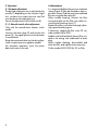
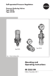
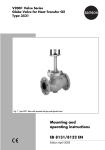
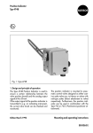
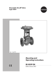
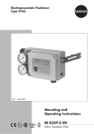
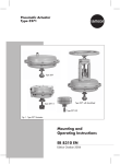
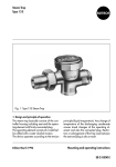
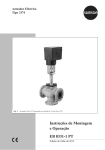
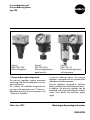
Pressure Regulator and
Pressure Reducing Station
Type 708
Figure 1
Type 708-1020
Pressure Regulator
Figure 2
Type 708-1025
Pressure Regulator, for
panel mountin
1. Design and principle of operation
The pressure regulator supplies pneumatic
measuring and control equipment with constant auxiliary air.
This reduces the available compressed air
pressure in the equipment max. 12 bar to a
adjustable minimum pressure between 0 to
1.6 bar or 0.5 to 6 bar.
Edition June 1997
Figure 3
Type 708-112
Pressure Reducing Station,
with manometer
In pressure reducing stations, the pressure
regulator is equipped with an upstream filter
and a downstream manometer.
Pressure regulators designed as build-on
blocks can be directly attached to positioners.
In addition, the pressure regulator can be
combined with a manual/automatic selector
switch which blocks the positioner output
signal.
Mounting and operating instructions
EB 8545 EN
Inlet
1
Outlet
1.1
3
3
4
5
4
2
5
1
2
7
6
6
1
1.1
2
3
4
5
6
7
8
8
7
1
2
3
4
5
6
7
Compressed air filter
Pressure regulator
Filter element
Serrated lock washer
Filter casing
Drain plug
Screw
Casing
Seat
Figure 5 ⋅ Pressure reducing station
Cover
Plug
Diaphragm
Diaphragm plate
Spring, depending on set point range
Spindle
Lock nut
Figure 4 ⋅ Pressure regulator
1
3
2
4
5
1
2
3
4
5
Casing
Nut
Screw
Gasket
Drain plug
Figure 6 ⋅ Pressure regulator
with build-on block
2
2
1
3
1 Casing
2 Piston
3 Locking plug
Figure 7 ⋅ Manual/Auto selector switch
Pressure regulator (Fig. 4)
The air pressure available at the regulator
input flows across the free area between the
seat (1.1) and the plug (3), and leaves the
outlet at a reduced pressure.
The output pressure is transmitted to the diaphragm (4) via a hole and produces an actuating force that is balanced by the power of
the spring (6).
If the spring is compressed by turning the
spindle (7), the diaphragm plate with diaphragm and plug moves upward. As a result,
the free area between the seat and the plug
becomes larger causing the output pressure
to increase.
If the output pressure becomes too high, or
the set point is reduced by relieving the spring
tension, the diaphragm plate is lifted from the
plug. The excess pressure is reduced to the
outside via the hole in the diaphragm plate
until a new state of equilibrium is achieved.
The pressure regulator set point ranges of 0
to 1.6 bar and 0.5 to 6 bar are determined
depending on the installed spring strength.
Pressure reducing station (Fig. 5)
The supplied compressed air flows through a
compressed air filter with a mesh size of
20 µm. If the air contains condensate, this
condensate flows off over the serrated lock
washer (4) and splashes centrifugally against
the filter walls. The collected condensate ca
then be drained via the drain plug (6).
Pressure regulator with build-on block
(Fig. 6)
The build-on block allows a simple mecha ical and pneumatic connection between the
pressure regulator and the various positioners.
For this purpose, special nuts (2) are screwed
into the associated tapped holes of the instruments intended for attachment to the regulator. The build-on block is then tightly secured
to the instrument using the hollow bored M8
special screws (3). The screws serve as air
ducts.
A gasket (4) on the casing seals the connec-
tion and the air duct is sealed by means of a
drain plug (5).
Manual/ auto selector switch (Fig. 7)
With Type 4763/ 4765 or 3766/ 3767 Positioners the switch makes it possible to block
off the positioner outlet and to manually actuate the control valve via the pressure regulator.
Automatic operation: In normal position,
when the slide valve piston (2) is pushed in
and the locking plug (3) is screwed on, the
signal pressure is connected to the actuator
via the selector switch.
Manual operation: In the “manual” position,
the piston (2) can be pulled out after the locking plug has been unscrewed. Thus, the actuator signal pressure line is blocked and the
pressure regulator output is directly connected to the actuator.
The valve can be adjusted by manually turning the regulator adjuster.
2. Installation
The pressure regulator can be mounted in
any position. It can be mounted to pipes or,
with mounting brackets, to panels, walls or
valves.
As pressure reducing station, the filter casing
with drain plug must be vertically installed.
The pressure reducing station should be
mounted as close to the compressor or compressed air reservoir as possible, in order to
avoid excessive trapping of water in long air
lines.
The air connections are given in G or NPT
thread sizes (refer to dimensions, chapter 5).
Attention must be paid to the direction of flo
at all times. The direction of flow or inlet and
outlet are indicated by arrows on the casing.
Assembly of the pressure regulator with
build-on block and positioner using special
nuts and banjo bolts is illustrated in figure 6.
The configuration is given in the respective
dimensional drawings in chapter 5.
3
3. Operation
4. Maintenance
3.1 Set point adjustment
It is recommended that the pressure reduction
station (figure 5) filter be checked as often a
possible. Let any fluid that may have collected
flow out using the drain plug (6).
When trouble shooting, unscrew the filter
casing and take out the filter insert after unscrewing the fastening screw (7).
Replace the filter insert after thorough cleaning in petrol and drying out.
If necessary, replace the filter insert 20 µm,
order number 8504-9027.
The desired output pressure is adjusted on the
spindle (7) depending on the set point. Right
turn increases the output pressure and left
turn decreases the output pressure.
Secure the adjustment with the lock nut (8).
3.1.1 Manual control valve adjustment
Only with the manual/auto selector switch
model.
Unscrew the drain plug (3) and remove the
piston (2) - the signal pressure to the actuator
is now blocked.
Bring the connected valve into the desired position using the pressure regulator spindle.
For automatic operation, push the piston
back and screw on the cap.
4
Models with build-on blocks have a filter situated in the casing inlet underneath a drain
plug.
When trouble shooting, disassemble and
clean the filter, and replace when necessary.
Order number 0559-0002 for 20 µm filter.
5. Dimensions in mm
46
25
15
32
134
117
77
12.5
4
11
72
11
44
4 .2
Ø
14.2
4 .2
Ø
44
3
42
32
Rotary
knob
Cover
Output
92(99 for NPT)
G¼
NPT ¼
G¼
NPT ¼
40
Ø
34
34
42
G¼
NPT ¼
40
Ø
40
Ø
Type 708-10.. Pressure Regulator for wall mounting
Type 708-00.. Pressure Regulator for
pipe mounting and Type 708-5003
for Type 3430 Controller Station
Type 708-11../12.. Pressure Regulator for
pipe or wall mounting
Input
G¼
~
~18
¼NPT
134
12 12
28
11
160
36
160
Output A2
G¼
, NPT¼
Output A1
G¼
, NPT¼
Build-on block with Type 708-52.2 Pressur
Regulator for Type 3772 Positioner
25
12
28
50
Supply air
G¼
, NPT¼
Type 3771
Supply air
G 1 4 , NPT 1 4
11
27
84
45
Build-on block with Type
708-56.2 Pressure Regulator for Type 6113 and
Type 6115 Electropneumatic Converters
42
12
Build-on block with Type 708-51.2 Pressur
Regulator for Type 3772 Positioner
118
Output
G 1 4 , NPT 1 4
11
Type 3771
Type 708-83.. Filter and Type 708-84.. Filte
Supply air
G¼
, NPT¼
Output A2
Output A1
G¼
, NPT¼
Input
G¼
, NPT¼
12
28
28
50
45
12
30
118
Output
59
15
G¼
¼NPT
Double nipple for attachment of a pressure regulator, a pressure reducing station
or a filter to the connection block of Type
3766 Pneumatic and Type 3767 Electropneumatic Positioners
42
50
Supply
air
G¼
NPT ¼
34
24
50
Supply
air
G1 8
NPT 1 8
Output
22
50
116
5
37
28
Without
With
Manual/Auto Selector Switch
Type 708-85.0
Manual/Auto
Selector Switch
74
Supply
Supply
54
24
Output
Build-on block with Type 708-55.2
Pressure Regulator for Type 4765
Pneumatic/4763 Electropneumatic
Positioner (optionally with Type 70885.0 Manual/Auto Selector Switch
38
Output
45
26
28
54
101
74
40
Ø
73
145
86
Solenoid valve
33
Air connections
G 1/4 NPT 1/4
73
Positioner
60
Pressure regulator
90
43
105
Type 708-5422 Pressure Regul tor for connecting a Type 3701
Solenoid valve or Type 4763 o
4765 Positione
84
40
Ø
83
50
161
106
SAMSON AG ⋅ MESS- UND REGELTECHNIK
Weismüllerstraße 3 ⋅ D-60314 Frankfurt am Main
Postfach 10 19 01 ⋅ D-60019 Frankfurt am Main
Telephone (0 69) 4 00 90 ⋅ Telefax (0 69) 4 00 95 07
Type 708-57... Pressure Regulator,
attached to Type 3760 Positioner
EB 8545 EN