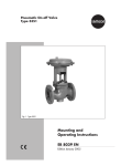
Download Mounting and Operating Instructions EB 2555 EN

Transcript
Self-operated Pressure Regulators
Pressure Reducing Valves
Type 50 ES
Type 50 EM
Type 50 EM
Type 50 ES
Fig. 1 · Pressure reducing valves
Mounting and
Operating Instructions
EB 2555 EN
Edition November 2011
Safety instructions
General safety instructions
4 The regulators must be installed, started up and serviced by fully trained
and qualified personnel only, observing the accepted industry codes and
practices. Make sure employees or third persons are not exposed to any
danger.
All safety instructions and warnings in these instructions, particularly those
concerning installation, start-up and maintenance, must be observed.
4 For appropriate operation, make sure that the regulator is only used in
applications where the operating pressure and temperatures do not exceed
the operating values based on the sizing data submitted in the order.
4 Note that the manufacturer does not assume any responsibility for damage
caused by external forces or any other external factors.
Any hazards which could be caused in the regulator by the process
medium or operating pressure are to be prevented by means of
appropriate measures.
4 Proper shipping and appropriate storage are assumed.
Definition of the signal words used in these mounting and operating instructions
NOTICE
Indicates a property damage warning.
Note:
Indicates supplementary explanations, information and hints.
2
EB 2555 EN
Design and principle of operation
1
Design and principle of
operation
The pressure reducing valves consist of a
valve with seat and soft-seated plug and a
valve bonnet with an operating diaphragm,
positioning spring(s) and a set point adjuster.
1
Type 50 EM has a pressure gauge connection
instead of a stopper (Type 50 ES). The connected pressure gauge indicate the downstream pressure p2.
3
The pressure reducing valve is designed to
maintain the pressure downstream of the
valve to an adjusted set point.
4
5
The valve is open when it is depressurized.
The valve closes when the pressure downstream of the valve rises above the adjusted
set point.
6
p2
p1
8
The process medium flows through the valve
between the seat (7) and the plug (8) in the direction indicated by the arrow. The position
of the valve plug determines the flow rate and,
hence, the pressure ratio across the valve.
The downstream pressure p2 is transmitted to
the operating diaphragm (4) and converted
into a positioning force. This force is used to
move the valve plug over the plug connection
link (6) depending on the force of the positioning spring(s) (3).
The spring force can be adjusted at the set
point adjuster (1).
7
9
1
3
4
5
6
7
8
9
Set point adjuster
Spring(s)
Operating diaphragm
Body
Plug connection link
Seat
Soft-seated plug
Stopper or connection for pressure gauge
p1
p2
Upstream pressure
Downstream pressure
Fig. 2 · Sectional drawing of Type 50 ES
EB 2555 EN
3
Installation
2
Installation
2.2
2.1
Mounting position
Install a strainer (SAMSON Type 1 NI with a
mesh size of 0.25 mm) upstream of the pressure reducing valve.
The pressure reducing valve can be installed
in any desired position.
4 The medium must flow through the valve in
the direction indicated by the arrow on the
valve body.
NOTICE
Protect the regulator against frost when the
process medium (e.g. water) can freeze.
Remove the valve from the pipeline while the
plant is shut down.
Note: Thoroughly flush the pipeline prior to
installation of the valve!
Otherwise sealing particles, globules and
other impurities carried along by the process
medium could impair the proper functioning
of the valve, especially the tight shut-off.
1
1
2
3
4
5
2
3
1
Shut-off valve
Pressure gauge for upstream pressure
Strainer
Type 50 ES Pressure Reducing Valve
Pressure gauge for downstream pressure
Fig. 3 · Typical installation
4
4 5
EB 2555 EN
Strainer
4 Make sure the process medium flow corre-
sponds with the direction indicated by the
arrow on the strainer.
4 In horizontal pipelines, install the strainer
with the filter
downwards.
element
suspended
4 In
upright pipelines where the medium
flows upwards, install the strainer with the
drain flange of the filter element facing
upwards. In this case, the dirt particles are
only retained, but not collected.
Ensure that enough clearance is provided to
remove the filter.
2.3
Shut-off valve and pressure
gauge
We recommend installing hand-operated
shut-off valves both upstream of the strainer
and downstream of the pressure reducing
valve. This allows the plant to be shut down
for cleaning and maintenance routines or
when the plant is not operated for extended
periods.
Install pressure gauges both upstream and
downstream of the pressure reducing valve in
order to monitor the pressures prevailing in
the plant.
Type 50 EM has a mounted pressure gauge
to indicate the downstream pressure p2.
Operation
3
Operation
During start-up, fill the plant slowly with the
process medium.
NOTICE
The pressure at the regulator must not exceed
the maximum permissible operating pressure
for the regulator.
3.1
Set point adjustment
Adjust the downstream pressure required by
turning the set point adjuster (1).
4 Turn the set point adjuster clockwise (P) to
increase the downstream pressure
4
Turn the set point adjuster counterclockwise (Q) to reduce the downstream pressure
The pressure gauge mounted on the
Type 50 EM Pressure Reducing Valve allows
the adjusted set point to be monitored directly
at the pressure gauge.
4
Maintenance
NOTICE
Remove the valve from the pipeline prior to
performing any work.
Make sure the relevant section of the plant has
been depressurized and, depending on the
medium, drained as well.
The pressure reducing valve is maintenance-free, but is subject to wear and tear,
especially at the seat and plug.
Depending on the application conditions that
prevail, the valve must be inspected at appropriately scheduled intervals to prevent any
problems before they occur.
If the valve does not shut off properly, this
may be due to dirt between the seat and plug
preventing tight shut-off or due to wear.
If external leakage occurs, check the operating diaphragm for leaks and replace the regulator, if necessary.
Prior to performing any cleaning routine, remove the pressure reducing valve from the
pipeline.
Proceed
1. Tension the spring(s) by turning the set
point adjuster (1) clockwise (P) to lift the
plug out of the seat.
2. Rinse the valve from both sides with water
to remove any dirt from the seat and
plug.
3. Release the spring tension by turning the
set point adjuster counterclockwise (Q)
and reinstall the valve in the pipeline.
EB 2555 EN
5
Dimensions
5
Dimensions
6
Customer inquiries
Should any malfunctions or any defect occur,
SAMSON's After-Sales Service is prepared
to help you on site.
113
37
60
Type 50 EM and Type 50 ES
Connection
G 3/8
Weight, approx.
All dimensions in mm
Fig. 4 · Dimensional drawing
6
EB 2555 EN
G½
0.7 kg
You can also send the defective regulator directly to your local SAMSON representative
for repair. Addresses of SAMSON subsidiaries, agencies and service centers are listed in
the product catalogs and in the Internet at
www.samson.de.
To allow SAMSON to find the fault and to
have an idea of the installation situation,
specify the following details (refer to the
nameplate):
4 Type and nominal size of the valve
4 Model number with index
4 Upstream and downstream pressures
4 Temperature and process medium
4 Min. and max. flow rates
4 Has a strainer been installed?
4 Installation drawing with exact location of
the regulator and all additionally installed
components (shut-off valves, pressure
gauges etc.).
EB 2555 EN
7
EB 2555 EN
2011-11
SAMSON AG · MESS- UND REGELTECHNIK
Weismüllerstraße 3 · 60314 Frankfurt am Main · Germany
Phone: +49 69 4009-0 · Fax: +49 69 4009-1507
Internet: http://www.samson.de