1
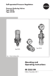
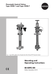
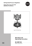
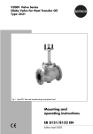
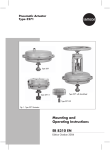
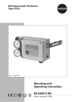
Pneumatic Control Valve Type 3331/BR 31a
Special version Type 3331/3278
Type 3331 Butterfly Valve
Fig. 1 · Type 3331/BR 31a (below) and Type 3331/3278 (top)
Mounting and
Operating Instructions
EB 8227 EN
Edition July 2004
Contents
Contents
Page
1
Design and principle of operation . . . . . . . . . . . . . . . . . . . 4
2
2.1
2.1.1
2.1.2
2.2
2.3
2.4
Installation . . . . . . . . . . . . . . . . . .
Assembling butterfly valve and rotary actuator .
Type 3331-BR 31a, Type SRP . . . . . . . . .
Type 3331/3278 . . . . . . . . . . . . . .
Mounting position . . . . . . . . . . . . . .
Test connection . . . . . . . . . . . . . . . .
Loading pressure connection . . . . . . . . .
3
3.1
Operation . . . . . . . . . . . . . . . . . . . . . . . . . . . . . . . 8
Changing the fail-safe position . . . . . . . . . . . . . . . . . . . . . 8
4
4.1
4.2
Maintenance . . . . . . . . . . . . . . . . . . . . . . . . . . . . . . 9
Packing . . . . . . . . . . . . . . . . . . . . . . . . . . . . . . . . 9
Removing the butterfly valve. . . . . . . . . . . . . . . . . . . . . . . 9
5
Customer inquiries . . . . . . . . . . . . . . . . . . . . . . . . . . 10
.
.
.
.
.
.
.
.
.
.
.
.
.
.
.
.
.
.
.
.
.
.
.
.
.
.
.
.
.
.
.
.
.
.
.
.
.
.
.
.
.
.
.
.
.
.
.
.
.
.
.
.
.
.
.
.
.
.
.
.
.
.
.
.
.
.
.
.
.
.
.
.
.
.
.
.
.
.
.
.
.
.
.
.
.
.
.
.
.
.
.
Note:
Non-electrical actuators and valves do not have their own potential ignition source according to the risk assessment in the rare incident of an operating fault, corresponding to EN
13463-1: 2001 paragraph 5.2, and therefore do not fall within the scope of the European
Directive 94/9/EC.
Refer to paragraph 6.3 of EN 60079-14:1977 VDE 0165 Part 1 concerning connection to
equipotential bonding system.
2
EB 8227 EN
6
6
6
7
8
8
8
Safety instructions
General safety instructions
4 The control valve may only be mounted, started up or serviced by fully
4
4
4
trained and qualified personnel, observing the accepted industry codes and
practices. Make sure employees or third persons are not exposed to any
danger. All safety instructions and warnings in these mounting and operating instructions, particularly those concerning assembly, start-up and maintenance, must be observed.
The control valves fulfill the requirements of the European Pressure Equipment Directive 97/23/EC. Valves with a CE marking have a declaration of
conformity that includes information about the applied conformity assessment procedure.
The corresponding declaration of conformity can be viewed and downloaded on the Internet at http://www.samson.de.
For appropriate operation, make sure that the control valve is only used in
areas where the operating pressure and temperatures do not exceed the operating values which are based on the valve sizing data submitted in the order. The manufacturer does not assume any responsibility for damage
caused by external forces or any other external influence! Any hazards
which could be caused in the control valve by the process medium, operating pressure, signal pressure or by moving parts are to be prevented by
means of the appropriate measures.
Proper shipping and appropriate storage of the control valve are assumed.
Caution!
4 For installation and maintenance work on the valve, make sure the relevant
4
section of the pipeline is depressurized and, depending on the process medium, drained as well. If necessary, allow the control valve to cool down or
warm up to reach ambient temperature prior to starting any work on the
valve.
Prior to performing any work on the valve, make sure the supply air and
control signal are disconnected or blocked to prevent any hazards that
could be caused by moving parts.
EB 8227 EN
3
Design and principle of operation
1
Design and principle of opera- Fail-safe positions:
tion
The fail-safe position of the control valve
The pneumatic control valve consists of a
Type 3310 Butterfly Valve and either a
Pfeiffer Type BR 31a Pneumatic Actuator or
a SAMSON Type 3278 Pneumatic Actuator.
The control valve is primarily intended for
throttling or on-off service in the process engineering industry and industrial applications.
It is suitable for liquids, vapors, and gases
with temperatures from −10 to +400 °C and
with nominal pressures from PN 10 to 40.
The butterfly valve in nominal sizes DN 100
to 400 can be designed depending on the
application with a swing-through or angle-seated/low-noise butterfly disc. The version used can be identified by a symbol on
the butterfly valve’s nameplate.
The process medium flows through the butterfly valve. The signal pressure acting on
the pneumatic actuator determines the position (opening angle) of the butterfly disc (8)
and the flow rate across the free area between disc and body (1).
The shaft is sealed by a packing (5). The actuator motion is transmitted over a squareended shaft. In Type 3331/3278, a shaft
with feather key (4.1) is used to transmit the
motion from the actuator to the shaft.
4
EB 8227 EN
upon failure of the supply air is determined
by the version of Type 3331/BR 31a (single-acting Type SRP) or depending on how
the rotary actuator is attached for
Type 3331/3278.
Valve CLOSED without supply air
The actuator springs close the valve when
the pressure is relieved from the rotary actuator or when the supply air fails.
The valve is opened opposing the force of
the actuator springs as the signal pressure
increases.
Valve OPEN without supply air
The actuator springs open the valve when
the pressure is relieved from the rotary actuator or when the supply air fails.
The valve is closed opposing the force of the
actuator springs as the signal pressure increases.
Design and principle of operation
Pfeiffer Type BR 31a Actuator
Type 3278 Actuator
Swing-through
disc
1
2
3
4
4.2
5
6
7
8
Valve body
Gland flange
Yoke
Shaft
Feather key
Packing
Spring
Tapered pins
Butterfly disc
9
10
12
12.1
12.2
13
13.1
13.2
Angle-seated/
low-noise disc
Internal bearing
Plug
Type BR 31a
Actuator
Stop
Stop screw
Type 3278 Actuator
Stop screw
Stop screw
Fig. 2 · Sectional diagram of the butterfly valve
EB 8227 EN
5
Installation
2
Installation
2.1
Assembling butterfly valve
and rotary actuator
Note!
The butterfly valve may be used for throttling
or on-off service.
For on-off service, the opening angle must
be set to 90° (70° with angle-seated discs)
using the stop screws.
For throttling service, the opening angle
must be set to 70° using the stop screws.
2.1.1 Type 3331-BR 31a, Type SRP
If the valve and actuator have not been preassembled by the manufacturer, proceed as
follows:
Note!
In the standard actuator version (SRP = single acting with spring-return mechanism)
the springs turn clockwise.
Should the springs turn counterclockwise,
this must be specified on ordering the actuator.
The rotary actuator can be mounted either
vertically or horizontally on the valve and
may be positioned at 90° around the valve
as required by the on-site conditions over a
square-end shaft.
6
EB 8227 EN
Valve CLOSED without supply air
1. Place disc (8) in closed position (0° angle of rotation).
2. Fasten yoke (3) with 2 or 4 screws depending on the nominal size of the valve
to the flange of the shaft (4).
3. Place shaft adapter (if required) onto the
shaft. Slide actuator over adapter (or
shaft) and fasten to the yoke using four
screws.
4. Turn the stop screw (12.1 or 12.2, depending on the direction of rotation) until the valve is completely closed.
Align the markings on the shaft with the
markings on the gland flange.
5. Secure the position of the stop screw
with its lock nut.
6. Apply a signal pressure to match the
number of springs (see nameplate) to the
loading pressure connection.
7. Turn the other stop screw until the disc
reaches the opening angle of 90° or
70°.
8. Secure the position of the stop screw
with its lock nut.
Valve OPEN without supply air
1. Place disc (8) in open position (90° angle of rotation).
2. Fasten yoke (3) with 2 or 4 screws depending on the nominal size of the valve
to the flange of the shaft (4).
3. Place shaft adapter (if required) onto the
shaft. Slide actuator over adapter (or
shaft) and fasten to the yoke (3) using
four screws (3.1).
Installation
4. Turn the stop screw (12.1 or 12.2, depending on the direction of rotation) until the valve is completely open at 90°.
Align the markings on the shaft with the
markings on the gland flange.
5. Secure the position of the stop screw
with its lock nut.
6. Apply a signal pressure to match the
number of springs (see nameplate) to the
loading pressure connection.
7. Turn the other stop screw until the valve
is completely closed.
Align the markings on the shaft with the
markings on the gland flange.
8. Secure the position of the stop screw
with its lock nut.
2.1.2 Type 3331/3278
If the valve and actuator have not preassembled by the manufacturer, the actuator is
mounted either to the flange 1 or 2 depending on the fail-safe position.
The digit 1 or 2 is cast on the flange on the
corresponding side of the body.
The rotary actuator can be mounted either
vertically or horizontally on the valve and
may be positioned at 90° around the valve
as required by the on-site conditions over
four feather key grooves arranged in stages
of 90° around the actuator shaft.
Valve CLOSED without supply air
1. Undo both stop screws (13.1 and 13.2)
at the actuator. Rescrew stop screw
(13.2) to the point where the grooves of
the actuator shaft are positioned vertically or horizontally to the actuator axis.
2. Place disc (8) in closed position (0°
angle of rotation).
3. Fasten yoke (3) with 2 or 4 screws depending on the nominal size of the valve
to the flange of the shaft (4).
4. Slide actuator over shaft (4) and fasten
tight at yoke (3) using the four screws.
5. Undo stop screw (13.2) again.
6. Turn the stop screw (13.2) until the valve
is completely closed.
Align the markings on the shaft with the
markings on the gland flange.
7. Apply the signal pressure required for
the spring range (see nameplate) to
achieve the opening position.
8. Turn the stop screw (13.1) until the disc
(8) reaches the open position (90° or
70° angle of rotation).
9. Secure the position of both stop screws
with their lock nuts.
Valve OPEN without supply air
1. Undo both stop screws (13.1 and 13.2)
at the actuator. Rescrew stop screw
(13.1) to the point where the grooves of
the actuator shaft are positioned vertically or horizontally to the actuator axis.
2. Place disc (8) in open position (90°
angle of rotation).
EB 8227 EN
7
Installation
3. Fasten yoke (3) with 2 or 4 screws depending on the nominal size of the valve
to the flange of the shaft (4).
4. Slide actuator over shaft (4) and fasten
tight at yoke (3) using the four screws.
5. Undo stop screw (13.1) again.
6. Apply the signal pressure required for
the spring range (see nameplate) to
achieve the closed position.
7. Turn the stop screw (13.1) until the valve
is completely closed.
Align the markings on the shaft with the
markings on the gland flange.
8. Disconnect the signal pressure.
9. Turn the stop screw (13.2) until the disc
(8) reaches the open position (90° or
70° angle of rotation).
10. Secure the position of both stop screws
with their lock nuts.
2.2
Mounting position
The butterfly valve may be installed vertically
or horizontally in the pipeline. However, the
following points must be observed for the direction of flow:
Mount the butterfly valve in the pipeline so
that the lower half of the disc opens towards
the direction of the flow. This helps prevent
any dirt deposits collecting which could prevent the disc from opening.
Butterfly valves with angle-seated/low-noise
(streamlined) discs must be mounted without
exception with the direction of flow indicated by the arrow on the valve body. On
mounting the valve between flanges in the
pipeline, place the disc in its closed position.
Take care not to damage the facings. On
tightening the flange bolts, make sure that
8
EB 8227 EN
the flat gaskets are compressed evenly.
The butterfly disc must move without any restrictions when the valve is installed in the
pipeline.
2.3
Test connection
Butterfly valves with a test connection to
monitor the packing (recognizable by a
label and hexagonal screw plug), must be
equipped with a suitable leakage indicator
such as a contact pressure gauge, outlet into
an open receptacle or sight-glass.
2.4
Loading pressure connection
The loading pressure connection of small rotary actuators is designed as a tapped G 1/8
hole and G 1/4 in large actuators.
Connection according to VDI/VDE 3845 allows also the attachment of solenoid valves
(e.g. Type 3963) or a limit switch with or
without solenoid valve (e.g. Type 3776/
3777).
In conjunction with SAMSON positioners,
suitable accessories are available for connection.
Operation
3
Operation
3.1
Changing the fail-safe
position
4
Note!
Before performing any maintenance
work on the control valve,
depressurize the concerned section
of the plant and drain the process
medium, if necessary.
Wait until the medium has cooled
down, if necessary.
We recommend removing the valve
from the pipeline.
Caution!
On performing any work on the
valve body, first shut off the supply
pressure, disconnect the supply pressure line and remove the actuator.
The fail-safe position of the Type 3278
Actuator can be changed from “Valve
CLOSED without supply air” to “Valve
OPEN without supply” or vice versa. To proceed, mount the rotary actuator on the other
side. Refer to section 2.1.2.
The pistons of the Type BR 31a Actuator
(SRP) must be installed in the reverse direction in the actuator.
Note!
Refer to the Mounting and Operating Instructions of the rotary actuator used for further details such as changing the spring
range to achieve other actuator torques.
Maintenance
4.1
Packing
Packing versions for use with temperature
ranges up to 220 °C are self-adjusting.
Packing suitable for higher temperatures up
to 450 °C can be adjusted. This packing
must be adjusted carefully on starting up the
plant by carefully tightening the gland
flange (2).
4.2
Removing the butterfly valve
Note!
On removing the butterfly valve from the
pipeline, make sure that the disc is in the
closed position.
EB 8227 EN
9
Customer inquiries
5
Customer inquiries
Please submit the following details:
4 Order number
4 Type designation, model number, nominal size and version of the valve
4 Pressure and temperature of the process
medium
4 Flow rate in m3/h
4 Bench range (spring range) of the actuator
4 Installation drawing
Dimensions and weights
Refer to the Data Sheet T 8227 EN for the
dimensions and weights of the various valve
versions.
10
EB 8227 EN
EB 8227 EN
11
EB 8227 EN
S/Z 2004-10
SAMSON AG ⋅ MESS- UND REGELTECHNIK
Weismüllerstraße 3 ⋅ 60314 Frankfurt am Main ⋅ Germany
Phone +49 69 4009-0 ⋅ Fax +49 69 4009-1507
Internet: http://www.samson.de