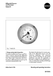
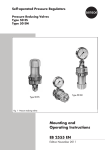
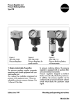
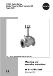
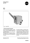
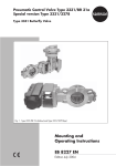
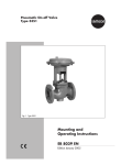
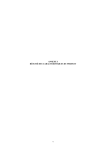
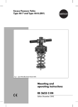
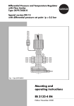
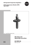
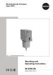
1
Self-operated Temperature Regulators Type 2430 K Thermostat for Series 43 Valves Type 2430 K Thermostat Mounted on a Type 2432 K Valve (Type 43-2 Temperature Regulator) Mounting and Operating Instructions EB 2430 EN Edition September 2014 Definition of signal words DANGER! Hazardous situations which, if not avoided, will result in death or serious injury WARNING! Hazardous situations which, if not avoided, could result in death or serious injury 2 NOTICE Property damage message or malfunction Note: Additional information Tip: Recommended action EB 2430 EN Contents 1 General safety instructions..............................................................................4 2 Process medium and scope of application........................................................5 2.1 Storage..........................................................................................................5 3 Design and principle of operation...................................................................6 4 Installation.....................................................................................................6 4.1 4.1.1 Installing the temperature sensor......................................................................7 Capillary tube................................................................................................7 5 Operation......................................................................................................9 5.1 Adjusting the set point.....................................................................................9 6 Technical data..............................................................................................11 EB 2430 EN 3 General safety instructions 1 General safety instructions −− The thermostat must be installed, started up or serviced by fully trained and qualified personnel only; the accepted industry codes and practices are to be observed. Make sure employees or third persons are not exposed to any danger. −− All the warnings given in these mounting and operating instructions must be strictly observed. −− According to these mounting and operating instructions, trained personnel refers to individuals who are able to judge the work they are assigned to and recognize possible dangers due to their specialized training, their knowledge and experience as well as their knowledge of the applicable standards. −− To ensure appropriate use, only use the thermostat in applications where the operating pressure and temperatures do not exceed the specifications used for sizing the thermostat at the ordering stage. −− The manufacturer does not assume any responsibility for damage caused by external forces or any other external factors. −− Any hazards that could be caused in the thermostat by the process medium, operating pressure or by moving parts are to be prevented by means of the appropriate measures. −− Proper transport, storage, installation, operation and maintenance are assumed. −− SAMSON does not assume any liability for damage caused when the device is not used as intended. 4 EB 2430 EN Process medium and scope of application 2 Process medium and scope of application When used in combination to a Series 43 Valve, the Type 2430 K Thermostat (adsorption principle) is used as a temperature regulator suitable for liquids, gases and vapors up to operating pressures up to 40 bar. It is particularly suitable for use in district heating supply networks. Refer to the Mounting and Operating Instructions of the temperature regulators for details: u EB 2171 EN Types 43-1 and 43-2 Regulators u EB 2172 EN Types 43-5, 43-6 and 43-7 Regulators u EB 2173 EN Type 43-3 Regulator u EB 2178 EN Type 43-8 Regulator (with Type 2430 K vapor pressure thermostat) Refer to EB 2430-3 EN for details on fast-responding Type 2430 K vapor pressure thermostats. Testing according to DIN EN 14597 The Type 2430 K Thermostat is tested by the German Technical Inspectorate (TÜV) according to DIN EN 14597 using the type designation 2750-0. The register number is available on request. 2.1 Storage Store within permissible ambient temperature range (–20 to +80 °C). Protect the thermostat against adverse influences, such as dirt or moisture during storage. EB 2430 EN 5 Design and principle of operation 3 Design and principle of operation The thermostat works according to the adsorption principle. The temperature of the controlled medium creates a pressure in the sensor (11) which is proportional to the measured temperature. This pressure is transferred through the capillary tube (10) to the operating element (13) and converted into a positioning force. The valve stem (4) is moved by the operating bellows (9) and pin of the operating element (12). By turning the set point adjuster (8), the point of response and the set point are changed over the spring (7). 4 Installation Note: Make sure that the permissible ambient temperature does not fall below –20 °C or exceed 80 °C. Install the valve in a horizontal pipeline. The control thermostat must be suspended to hang downward. Other mounting positions are possible under certain operating conditions. Refer to the mounting and operating instructions of the temperature regulator. Detailed view 4 Tightening torque 20 Nm 14 15 Metal retaining ring Rubber seal Capillary tube 10 7 8 11 9 12 13 Fig. 1: Type 2430 K Thermostat attached to a Series 43 Valve 6 Metal retaining ring 4 7 8 9 10 Plug stem Set point spring Set point adjuster Operating bellows Capillary tube 11 Temperature sensor 12 13 14 15 Pin of operating element Operating element Lead-seal hole Coupling nut EB 2430 EN Installation Install a thermometer immersed in the medium to be controlled, close to the sensor. This allows you to monitor the adjusted set point temperature and regulate the set point at the thermostat accordingly. 4.1 Installing the temperature sensor The temperature sensor may be installed in any position. However, make sure its entire length is immersed in the process medium to be controlled. Select a place of installation where overheating and noticeable idle times will not occur. Weld a welding socket with G ½ female thread (for a sensor with 9.5 mm diameter) or G ¾ female thread (for a sensor with 16 mm diameter) at the place of installation. Seal the screw gland or thermowell in the welded-in socket and tighten the clamping screw to fasten it. NOTICE On installing the sensor or thermowell, only use similar materials (e.g. stainless steel with stainless steel or copper together with other copper materials) to prevent corrosion. Special version with thermostat (operating according to the vapor pressure principle) Refer to u EB 2430-3 EN for special installation instructions. The temperature sensors operating according to the vapor pressure principle are particularly suitable for use in plate heat exchang- EB 2430 EN ers due to the fast response time of approx. 3 s. To install the sensor in a plate heat exchanger, insert it horizontally into the hot water duct, making sure that the notch on the sensor faces upward. Screw the sensor’s thread connection into the adapter. Align the sensor using the clamping screw and tighten it by hand. _125 > 2) _140 > A 5 1) Adapter with temperature sensor Notch Threaded connection (max. 20 Nm) Clamping screw 2.5 mm hexagon socket All dimensions in mm Plate heat exchanger <130 mm Plate heat exchanger >130 mm 1) 2) Fig. 2: Sensor (working according to the vapor pressure principle), installation in plate heat exchanger 4.1.1 Capillary tube Install the capillary tube in such a way that mechanical damage cannot occur. The minimum bending radius is 50 mm. Any excess length of the capillary tube must be rolled up into a ring. Do no bend or shorten the capillary tube under any circumstances. 7 Installation Make sure that the temperature at the capillary tube remains within the permissible ambient temperature range and is not exposed to considerable temperature fluctuations. Table 1: Thermostats (operating according to the vapor pressure principle) · Mounting position and materials Type 2430 K Thermostats (according to vapor pressure principle) · 45 to 65 °C Configuration ID (Var.-ID) Plate heat exchangers 1) Sensor position Sensor material 1058730 1109125 Horizontal • Tip facing upward – Tip facing downward – CrNiMo steel • Sensor connection, screw gland G½ Without Length of capillary tube Configuration ID (Var.-ID) Sensor position Shell-and-tube or coaxial heat Sensor exchangers material 1) 2m 1045853 1067861 1045883 Horizontal • • • 1072710 • Tip facing upward – – • • – Tip facing downward • • – Copper • – • – CrNiMo steel – • – • Sensor connection, screw gland G½ Length of capillary tube 2m Type 43-8, with instantaneous plate heat exchangers 8 EB 2430 EN Operation 5 Operation 5.1 Adjusting the set point Turning the adjuster clockwise (): Turn the black plastic adjuster (8) to adjust the set point while watching the reference thermometer. The adjustment diagrams can be used as a guide to find the first approximate values. −− The (set point) temperature is reduced. Turning the adjuster counterclockwise (): −− The (set point) temperature is raised. The adjusted set point can be lead-sealed at The temperature changes are specified in Table 2 per turn of the thermostat the hole (14). Table 2: Adjustment values Set point ranges 25 to 70 °C 40 to 100 °C 50 to 120 °C Sensor Ø in mm 9.5 0 to 35 °C 16 9.5 16 9.5 16 9.5 16 9.5 16 Changes per turn in K 2.5 2 3 2 4 3 4 4.5 4.5 5 DN 15 to 25 ˚C 70 to 150 °C DN 32 to 50 ˚C Set point 150 70...150˚C 140 Set point 150 70...150˚C 140 120 50...120˚C 120 50...120˚C 100 40...100˚C 100 40...100˚C 80 80 Set point ranges 60 25...70˚C 60 40 0...35˚C 20 0 Set point ranges 25...70˚C 40 0...35˚C 20 0 1 2 3 4 0 Turns (scale markings) 0 1 2 3 4 Fig. 2: Adjustment diagrams for Types 43-1, 43-2, 43-5 and 43-7 Regulators (adsorption principle) EB 2430 EN 9 Operation DN 15 to 25 ˚C DN 32 to 50 ˚C Set point Set point 150 140 70...150 150 140 70...150 120 50...120 120 50...120 100 40...100 100 40...100 80 Set point ranges 80 25...70 Set point ranges 25...70 60 60 40 40 0...35 0...35 20 20 0 0 1 2 3 4 Turns (scale markings) 0 1 2 Fig. 3: Adjustment diagrams for Type 43-6 Regulator (adsorption principle) 0 °C 3 4 Set point 80 55 to 75 °C (special version) 75 70 With Type 43-8 65 60 45 to 65 °C 55 50 45 40 0 0 1 2 3 3.5 4 Turns (scale markings) Fig. 4: Adjustment diagrams for Type 43-8 Regulator (Type 2430 K vapor pressure thermostat) 10 EB 2430 EN Technical data 6 Technical data Table 3: Technical data Thermostat Type 2430 K Adsorption principle Type 2430 K Vapor pressure principle Control thermostat Fast-response control thermostat Version For valve size DN 15 to 25 DN 32 to 50 DN 15 to 50 G ½ to G 1 – G ½ to G 1 G ½ G ¾ G ½ Sensor connection 0 to 35 °C · 25 to 70 °C · 40 to 100 °C 50 to 120 °C · 70 to 150 °C Set point ranges Permissible ambient temperature range –20 to +80 °C Capillary tube length 2 m Ø 9.5 x 170 mm, copper, PN 25 Sensor Mounting position 1) 45 to 65 °C Ø 16 x 210 mm, copper, PN 25 Ø 10 x 170 mm 1), copper, PN 25 Horizontal or tip pointing up/down Any desired position Sensor Ø 12 x 170 mm or Ø 12 x 160 mm: Horizontal mounting position for plate heat exchanger Table 4: Accessories Order listed accessories from SAMSON, specifying the order number. G ½ G ¾ Copper, PN 40 1390-8984 1090-8465 CrNiMo steel, PN 40 1390-8983 1190-1522 1180-9510 1180-9511 1990-1712 – Double adapter Do3 K 1180-8632 – Manual adjuster 2) 1790-8169 – Sensor connection Type 2430 K thermowell Types 2430 K and 2439 K: thermowell for flammable gases typetested by DVGW, PN 100, made of CrNiMo steel Intermediate insulating piece 1) (for Type 43-3 and Type 43-6) for medium temperature down to –15 °C with red brass valve bodies Order no. 1) Not with oil-resistant version 2) A double adapter Do3 K is required when used together with Type 2430 K EB 2430 EN 11 Weismüllerstraße 3 · 60314 Frankfurt am Main, Germany Phone: +49 69 4009-0 · Fax: +49 69 4009-1507 [email protected] · www.samson.de EB 2430 EN 2014-10-01 · English SAMSON AG · MESS- UND REGELTECHNIK