1
RO326PN1
RoboBall FlyEye Sensor
Operating Instructions
RO326PN1-DC1V2 operating instructions
Page 1 of 4
The RoboBall FlyEye Sensor has been designed
to be used with pre-programmed robots competing in
the ‘RoboCup Junior’ * competitions.
The RoboBall FlyEye Sensor was born out of
practical experience with the most common and
frustrating problem encountered in constructing a
soccer robot - reliably finding the ball!
Features of the RoboBall
•
•
•
•
•
•
FlyEye Sensor:
Designed to work directly with LEGO RCX*.
No modifications necessary to work with 2 wire
interfaces.
16 output levels, relative to the ball’s direction
and the sensor’s distance from ball (intensity).
Standard 3 wire interface.(See Section 5)
Designed to operate at 7.2V - 12VDC.
Designed to interface directly to the A to D input
of a microprocessor
Mechanical Specifications:
31mm
52mm
+VE -VE O/P
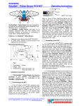
Fig.1
•
•
Dimensions : ± 0.5mm
Weight : 65g
Electronic Specifications
•
•
•
Input Voltage
Input Current
Output Voltage
: 7.2VDC - 12VDC
: 10mA (max)
: see Table 1.
1. Installation Instructions
modifications. All you need a LEGO extension lead
that has been cut to a desired length and then
separated and stripped 3 - 5mm. Heat shrink tubing
10mm in length is slid over the separate Red and
Black RoboBall FlyEye wires, before the wires
are soldered onto the LEGO extension lead. The
heat shrink is slid back over the joints and carefully
heated to insulate the terminations. Now the LEGO
block can be plugged onto the appropriate RCX*
input. (Section 1.5 & 1.6 will check correct
orientation of block on RCX* for polarity purposes)
The photodiode detectors are mounted on the
underside of the PCB such that the overhang of the
PCB helps shield them from the effects of intense
overhead lights that could potentially confuse the
RoboBall FlyEye. Hence it is important you have
it the right way up!
FlyEye’s PCB
1.2 Mount the RoboBall
horizontally at mid height of the RoboBall . There
is some advantage to mounting the RoboBall
FlyEye higher and tilting it slightly downwards as
this can reduce the sensitivity to external light
sources around the soccer field. The vertical field of
view extends 20° above the plane of the PCB (at
50% sensitivity) which means a bright infra-red light
source may be detected in the distance if it is low
enough to be within the RoboBall
FlyEye’s
viewing region - sunlight coming through distant
windows is a particular problem. Fluorescent lighting
contains little infra-red light and will have less effect
on the sensor than incandescent lights or sunlight. If
you are careful, you might choose to bend all the
photodiodes away from the PCB slightly as an
alternative to tilting the PCB. The 4 holes in the PCB
(see Fig.2) can be used to assist with mounting the
RoboBall FlyEye Sensor to your robot. However
due to slight hole size and hole to hole distance
variations in the PCB manufacturing process we do
not recommend that these holes are used for power
connections, as they may prove to be unreliable.
1.3 The intensity of the light emitted by a
RoboBall can vary depending on whether one of
the LEDs is facing you. Therefore make sure that
when you mount the RoboBall FlyEye, the plane
of maximum sensitivity is directed towards the
centre of the ball when it is close up. This gives the
RoboBall FlyEye the best chance of catching the
output from at least one of the RoboBall LEDs as
the ball rotates.
1.4 The RoboBall
be ready for use.
1.1 The RoboBall
FlyEye Sensor may be
simply connected to your standard RCX* ‘2 wire’
interface (for LEGO MINDSTORM etc.) with no
FlyEye Sensor should now
1.5 You will need to write a small RCX* program
to configure one of the input ports as a powered
sensor and then change the sensor to ‘raw’ mode.
______________________________________________________________________________________________________
WILTRONICS RESEARCH PTY LTD PO Box 4043, Alfredton 3350, AUSTRALIA
Ph. +61 3 5334 2513 Fax +61 3 5334 1845 http:/ www.wiltronics.com.au
RO326PN1
RoboBall FlyEye Sensor
Operating Instructions
RO326PN1-DC1V2 operating instructions
(See the programming section if you are not sure
how to do this.) Download the program and run it.
Press the ‘view’ button on the RCX* to view the port
you have just configured. With nothing plugged into
the port, the display should read 1023, if not, then
check your program. If you plug a standard Lego*
light sensor into the port then the red LED on the
sensor should light up; again, if this doesn’t happen,
check the port configuration before proceeding.
1.6 Now plug the RoboBall FlyEye into the
port that you just configured and double check that
the display is still ‘viewing’ that port. Unlike Lego light
sensors, the RoboBall FlyEye will only operate
correctly if it is plugged into the RCX* port the correct
way round. Don’t worry; the RoboBall FlyEye has
protection against the reverse polarity that occurs
when it is plugged in the wrong way. If you see a
constant number close to 630 displayed on the RCX
then you need to reverse the connector. When you
plug the RoboBall FlyEye in the right way round it
will go through an initial ‘power-on’ test which will
result in a sequence of readings beginning at
approximately 925. After about 1 second, the
displayed value should decrease, over a period of 1.5
seconds, until a number close to 250 is displayed for
a further 1 second. If this sequence of numbersis
displayed on the your RCX the RoboBall FlyEye is
working properly and you have connected it correctly.
Don'
t worry if the numbers are not exactly 925 or 250
etc. there is always some slight variation between
devices.
1.7 After the initial power-on test, the displayed
values will start to change depending on what the
RoboBall
FlyEye senses. Remember that the
RoboBall FlyEye goes through a ‘self test’ every
time it is turned on; so make sure that you have your
robot turned on at least a few seconds before you
need to run your soccer program!
2. Understanding how it works!
2.1. There are seven photodiodes (see Fig 3) on
the underside of the RoboBall FlyEye and these
look in different directions. A microcontroller, built into
the RoboBall FlyEye, compares the light intensity
seen by each of the seven photodiodes and picks the
brightest one. The RoboBall FlyEye can send 16
different voltage levels to your robot. On an RCX*
port in ‘raw’ mode these correspond roughly to values
starting at 250 and increasing in steps of 45, i.e. 250,
295, 340, 385, 430, 475, 520, 565, 610, 655, 700,
745, 790, 835, 880 & 925. (See the 3 -wire interface
section for the actual voltage levels) Note these
values are approximate and will depend on the exact
setting of VR1 (see the adjustments section), there
will also be some variation in the values during
normal operation and your program must be written
Page 2 of 4
to deal with this. The lowest 7 values (250 - 520) are
used to indicate which photodiode is detecting the
brightest light. A value of 250 indicates the brightest
light is distinguished by the far left photodiode, a
value of 385 indicates straight ahead and a value of
520 is far right. The highest nine values (565 - 925)
are used to indicate the intensity of the light seen by
the brightest photodiode. See the ‘adjustments’
section for more information on the intensity values.
Fig 2
2.2. The RoboBall FlyEye switches between
indicating direction and intensity about ten times per
second when the light source is steady. However, if
the direction to the brightest light changes then the
RoboBall
FlyEye gives priority to direction
information and will output the new direction value
immediately and in preference to a new intensity
value. Having said that, an intensity value will
always be output at least 5 times a second. See the
programming section for more information on how to
use the values read from the RoboBall FlyEye.
2.3. Note that when you use the ‘view’ button to
look at the output of the RoboBall FlyEye the
RCX* refreshes the display quite slowly, such that
you will not see the RoboBall
FlyEye values
change 10 times per second. However a properly
written program will have no trouble reading these
rapid changes.
3. Adjustments.
3.1. There are two adjustments available on the
RoboBall FlyEye set by VR1 & VR2, shown in Fig
1 & Fig 2. These are pre-set at the time of
manufacture and should not need altering.
3.2. VR1 adjusts the ‘digital’ output levels. To set
this, locate the RoboBall FlyEye so that the far
left photodiode is facing a very bright light and the
output switches between the minimum and
maximum values (250 and 925), realistically 275 and
900. Rotating VR1 will adjust the range.
______________________________________________________________________________________________________
WILTRONICS RESEARCH PTY LTD PO Box 4043, Alfredton 3350, AUSTRALIA
Ph. +61 3 5334 2513 Fax +61 3 5334 1845 http:/ www.wiltronics.com.au
RO326PN1
RoboBall FlyEye Sensor
Operating Instructions
RO326PN1-DC1V2 operating instructions
3.3. VR2 adjusts the optical scale. The
RoboBall FlyEye detects light on a ‘logarithmic’
scale. That means that light levels corresponding to
successive output values differ by the same factor.
This is similar to how a human eye perceives
intensity and means that the RoboBall FlyEye can
indicate intensities ranging from bright sunlight to a
dimly lit room on the one scale. The best guide to
adjusting the optical intensity covered by the scale is
to put the soccer ball as close as possible to the
RoboBall FlyEye and adjust VR2 until the intensity
just registers at the top of the scale i.e Max. 920 (875
– 925).
4. Programming
4.1 This section is for RCX* based robots, but
you can use it as a general guide for other platforms.
The first step is to configure the input port to be a
powered sensor (i.e light sensor). The RCX* reads
all sensors on a range 0 to 1023 but then applies a
conversion depending on what type of sensor is
being used. The conversions used for the various
Lego* sensors are not compatible for the
RoboBall FlyEye so the next step is to configure
the RCX* to display ‘raw’ readings. If you are using
NQC and have the RoboBall FlyEye on Port 1
then the two commands to use are:
SetSensor (SENSOR_1, SENSOR_LIGHT);
SetSensorMode (SENSOR_1,SENSOR_MODE_RAW);
If you are using Robolab* then use the Powered
Sensor Container VI to store the RoboBall FlyEye
reading in a container. In the example below, the
RoboBall FlyEye would be plugged into port 1.
Page 3 of 4
{
int Temp;
Temp = (SENSOR_1 - 230)/45;
if (Temp<7)
Direction = Temp;
else
Intensity = Temp-7;
}
In this example, values up to 274 will be converted
to Direction = 0, and values between 275 and 319
converts to Direction = 1 and so on. The nominal
output levels of the RoboBall FlyEye, 250, 295
etc will fall in the middle of these ranges and give
the best immunity to any noise on the output.
4.3 In Robolab* you can do a similar conversion
using a Formula Container VI to do calculations with
the number stored by the Powered Sensor
Container VI.
Whether you use NQC or Robolab*, make sure that
FlyEye value into a
you read the RoboBall
container and then use the stored value to do
related calculations or branches in your program.
The value read from the port can change at any
time and there is no guarantee that two successive
reads from the port will return the same value no
matter how close together they are in your program.
Because the RoboBall FlyEye can switch its
output ten or more times a second you need to
ensure your program calls the reading function
(SubVI) at least 20 times a second if it is not to miss
an important change in direction - the ball can move
a surprising distance in a tenth of a second! You
might consider using a separate task to read the
RoboBall FlyEye so that the values are always
kept up to date. This simplifies the programming but
be aware that the RCX* multi-tasking sometimes
creates unexpected problems when your robot
needs fast reactions.
+VE
-VE
4.2 To simplify the logic and to compensate for
the effects of small variations in the RoboBall
FlyEye output it is a good idea to convert the raw
values into something easier to interpret. The
following NQC function shows one way you might do
this:
Output
int Direction;
int Intensity;
void Read FlyEye ()
Fig. 3
______________________________________________________________________________________________________
WILTRONICS RESEARCH PTY LTD PO Box 4043, Alfredton 3350, AUSTRALIA
Ph. +61 3 5334 2513 Fax +61 3 5334 1845 http:/ www.wiltronics.com.au
RO326PN1
RoboBall FlyEye Sensor
Operating Instructions
RO326PN1-DC1V2 operating instructions
5. ‘3 wire’ operation
5.1 The output of the RoboBall
FlyEye is
available on the ‘3 wire’ pad (see Fig 3 above and
Fig 1 for a top view) for use with platforms other than
an RCX*. Simply solder an additional wire to this
Output Pad and connect it to your robot’s input. The
RoboBall FlyEye needs between 7.2VDC and
12VDC connected to the supply pads to operate.
The square pad is positive.
5.2 The port values 0 to 1023 on an RCX*
correspond to 0 to 5 V on the RoboBall FlyEye
output. So 250 correspond to approximately 1.22
Volts and 925 to about 4.52 Volts. The step size of
45 corresponds to changes of approx. 0.22 Volts.
6. More testing...
By now you probably know that the secret to good
robotics is test, test and test again. So, once you
have the RoboBall FlyEye plugged in and have
observed the initial power on test and understood
what the output values mean, perform the following
simple test to demonstrate the RoboBall FlyEye’s
operation.
You need a single bright light (a desk lamp or torch
for example) in an otherwise dimly lit room. Make
sure the RCX* has run a program to set the input port
correctly and cycle the RCX* display to the
RoboBall FlyEye port with the view button. Turn
the light on and position the RoboBall FlyEye so
that the far left photodiode (looking from the top of
the board) is facing the light. Watch the RCX*
display; you should see it change between a number
near 250 and a number higher than 600. A very
bright light like a quartz halogen desk lamp should
read a value near 900 at close range. Slowly rotate
the RoboBall FlyEye or move the light so that
each of the other photodiodes faces the light in turn.
The display should alternate between the higher
intensity value and a different lower value depending
on which photodiode faces the light. When the bright
light is straight ahead the lower value should be
about 385 and when it is to the far right, about 520.
Again, some variation in these values is normal and
the values may be altered using the setting of VR1.
Now change the intensity, either by moving away
from the light or by shading some of the light near the
source, you should now see the intensity value (the
higher number that is displayed) decrease.
If you’re not using an RCX*, then you can view the
RoboBall FlyEye output with a digital multimeter
but be aware that some multimeters will not read the
Page 4 of 4
output correctly as it switches rapidly between the
different output voltages.
7. Other things to think about...
You’ll notice that the photodiodes are spaced closer
together towards the forward direction. Arranging the
photodiodes this way gives your robot the most
precise information about changes in ball location
where it needs it most, just like a human eye which
perceives more detail in the centre of vision with
only vague detail on the periphery. The field of view
of the individual photodiodes is wide enough that
they overlap their neighbour’s field of view. So there
are no ‘gaps’ in the RoboBall FlyEye’s vision.
The most obvious way to make use of the
RoboBall FlyEye output is to have your robot turn
until the ball is directly ahead and then move
forward. If the ball moves to one side or the other
your robot can correct its direction while still giving
chase. But you can also have your robot turn until
the ball is in front of one of the other photodiodes.
With a slight change of programming you can have
your robot hit the ball from the left or right or even
circle around it. Experiment and have fun!
“RoboBall
FlyEye Sensor” Design & Specifications:
Copyright ©Wiltronics Research Pty Ltd
Solutions Pty Ltd 2005
& IME Consulting
Australian Innovation Patent No.2005100750
RoboBall
is a Trademark of Wiltronics Research Pty Ltd
*LEGO , *LEGO MINDSTORM, & *RCX are Registered Trade
Marks & Trade Marks of the LEGO GROUP OF COMPANIES
Robolab
is a registered Trade Mark of Tuft’s University
*ROBOCUP JUNIOR is a Registered name of the
ROBOCUP FEDERATION
DESIGNED AND MANUFACTURED IN AUSTRALIA
______________________________________________________________________________________________________
WILTRONICS RESEARCH PTY LTD PO Box 4043, Alfredton 3350, AUSTRALIA
Ph. +61 3 5334 2513 Fax +61 3 5334 1845 http:/ www.wiltronics.com.au