1
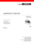
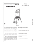
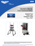
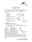
INSTALLATION & OPERATING
INSTRUCTIONS
for
REDCO® INSTACUT™ 3.5
REDCO® INSTACUT™ 3.5W
Shown with optional accessories
TO BE SERVICED ONLY BY AUTHORIZED PERSONS
P/N: 2803054
REV: C
WARNING AND SAFETY INFORMATION
!
WARNING
!
THIS MACHINE CONTAINS SHARP BLADES AND CAN CAUSE SERIOUS INJURY OR DEATH IF NOT
HANDLED PROPERLY. ALL OPERATORS OF THIS EQUIPMENT SHOULD READ THIS OPERATION
MANUAL BEFORE OPERATING EQUIPMENT.
IN ORDER TO AVOID DAMAGE TO PEOPLE AND THE APPLIANCE, READ AND FOLLOW THE
MANUFACTURER’S INSTRUCTIONS FOR THE CLEANING OF THIS EQUIPMENT.
LIMITED TWO (2) YEAR WARRANTY
Lincoln Foodservice Products, LLC (“Lincoln”) warrants, to the original purchaser for use in the United States of
America, that each new item of Redco food preparation utensils (other than blades) manufactured by it (“Warranted
Product”) is free of defects in material and workmanship under normal use and conditions.
The exclusive remedy available under this Limited Warranty is that Lincoln will, free of charge, but at its option,
subject to, and in accordance with the terms and conditions of this Limited Warranty, repair or replace, for the
original purchaser for use in the United States of America, any Warranted Products or part thereof that proves to be
defective with the same or a similar item or part, it is returned to Lincoln in accordance with the procedure set out
on the warranty card.
This Limited Warranty applies only to original parts of Warranted Products sold for use in the United States of
America and does not apply to any Warranted Products located outside the United States of America, regardless of
where sold, or to any item or part thereof that has been subjected to accident, casualty, alteration, misuse, or abuse
or if the date of manufacture is altered or removed.
THIS LIMITED WARRANTY DOES NOT APPLY TO BLADES WHICH ARE SOLD COMPLETELY WITHOUT
WARRANTY OR GUARANTEE OF ANY KIND, EXPRESSED OR IMPLIED. THE OBLIGATION OF LINCOLN IS
LIMITED TO THE ABOVE AND, EXCEPT AS EXPRESSLY STATED HEREIN, LINCOLN MAKES NO
GUARANTEES OR WARRANTIES, EXPRESSED OR IMPLIED, INCLUDING WITHOUT LIMITATION,
WARRANTIES OF FITNESS OR MERCHANTABILITY, WITH RESPECT TO WARRANTED PRODUCTS.
LINCOLN SHALL NOT BE LIABLE FOR SPECIAL, INCIDENTAL, OR CONSEQUENTIAL DAMAGES OF ANY
KIND. NO ONE IS AUTHORIZED TO MAKE ANY GUARANTEES OR WARRANTIES, EXPRESSED OR
IMPLIED, ON BEHALF OF LINCOLN.
SOME STATES DO NOT ALLOW LIMITATIONS OF IMPLIED WARRANTIES, OR THE EXCLUSION OR
LIMITATION OF INCIDENTAL OR CONSEQUENTLY DAMAGES IN CONNECTION WITH THE SALE OF
CONSUMER PRODUCTS, CONSEQUENTLY, IF YOU ARE A CONSUMER, AS THAT TERM IS LEGALLY
DEFINED, THE ABOVE LIMITATION OR EXCLUSION MAY NOT APPLY TO YOU.
TABLE OF CONTENTS
Warning and Safety Information……..……………………………………………………………………………………….. 2
Limited Warranty Statement……..……………………………………………………………………………………………. 2
Unit Descriptions……………………………………………………………………………………………………………...…3
Operating Instructions………………………………………………………………………………………………………….. 4
Cleaning Instructions…….…………………………………………………………………………………………………..… 4
Blade Replacement Instructions……………………………………………………………………………………………… 5
InstaCut 3.5 Parts List……………..……………………………………………………………………………………………6
InstaCut 3.5 Exploded View Drawing……………………….………………………………………………………..………. 7
InstaCut 3.5W Parts List…………..…………………………………………………………………………………………… 8
InstaCut 3.5W Exploded View Drawing……………………….……………………………………………………..………. 9
2
InstaCut Ops Manual
UNIT DESCRIPTIONS
INSTACUT 3.5 (TABLETOP UNIT)
Catalog Number
15000
15001
15002
15003
15005
15006
15007
15008
15009
15010
Description
InstaCut 3.5 Tabletop Unit, ¼” Dice
InstaCut 3.5 Tabletop Unit, ⅜” Dice
InstaCut 3.5 Tabletop Unit, ½” Dice
InstaCut 3.5 Tabletop Unit, 4 Section Wedge
InstaCut 3.5 Tabletop Unit, 6 Section Wedge
InstaCut 3.5 Tabletop Unit, 8 Section Wedge
InstaCut 3.5 Tabletop Unit, 10 Section Wedge
InstaCut 3.5 Tabletop Unit, 12 Section Wedge
InstaCut 3.5 Tabletop Unit, 6 Section Core
InstaCut 3.5 Tabletop Unit, 8 Section Core
INSTACUT 3.5W (WALL-MOUNTED UNIT)
Catalog Number
15016
15017
15018
15019
15021
15022
15023
15024
15026
Description
InstaCut 3.5 Wall-Mount Unit, ¼” Dice
InstaCut 3.5 Wall-Mount Unit, ⅜” Dice
InstaCut 3.5 Wall-Mount Unit, ½” Dice
InstaCut 3.5 Wall-Mount Unit, 4 Section Wedge
InstaCut 3.5 Wall-Mount Unit, 6 Section Wedge
InstaCut 3.5 Wall-Mount Unit, 8 Section Wedge
InstaCut 3.5 Wall-Mount Unit, 10 Section Wedge
InstaCut 3.5 Wall-Mount Unit, 12 Section Wedge
InstaCut 3.5 Wall-Mount Unit, 8 Section Core
InstaCut 3.5W wall mounted units are designed to accept ¼” diameter mounting
!
NOTE: hardware. Be sure to use ¼” diameter mounting hardware when attaching to wall studs
!
WARNING: proper operation and employee safety. Improperly installed units can result in employee
to provide for a secure installation.
It is imperative that a wall-mounted unit be installed securely to wall studs to insure
InstaCut Ops Manual
injury and structural damage!
3
!
CAUTION:
!
Blades are sharp and can cause injury. Check machine before using. Be sure machine is clean. Check for
broken, nicked or dull blades and if found, replace blade assembly. Check to ensure that the pusher head sits
down completely on the rubber bumpers. The suction cups on each rear leg will hold the InstaCut securely to
smooth surfaces. If necessary, lubricate guide rods using a light coating of mineral oil, Petrol Gel or food
grade lubricant. DO NOT LUBRICATE WITH COOKING OIL AS IT WILL BECOME STICKY.
CAUTION:
!
PRIOR TO FIRST USE, IT IS IMPORTANT TO CLEAN THE UNIT. WASH NEW
BLADES WITH WARM SOAPY WATER AND RINSE THOROUGHLY TO REMOVE
THE THIN PROTECTIVE OIL FILM.
OPERATING INSTRUCTIONS
1. Check machine before using to ensure unit is clean. Check for broken, nicked or dull blades and if found,
replace blade assembly. Check to ensure that the pusher head sits down completely on the rubber
bumpers. With table-top units, the suction cups on each rear leg will hold the unit securely to smooth
surfaces. To remove, push unit to the rear while releasing suction on legs.
2. Prepare the produce to be diced by cutting to your specifications. Maximum size of produce that will go
through the dicer, wedger, and corer is approximately 3 ½” across.
3. Place hand on the handle, lift the pusher head and place product on the blades, flat side down.
4. Remove hand and fingers from cutting area, place that hand on dicer leg, leave the other hand on the Thandle. Then, with a strong, quick, downward thrust, force the produce through the blades.
5. If the pusher head does not slide freely on the guide rods, lubricate with mineral oil or Petro Gel. Never
use cooking oil as it will cause the unit to become sticky!
CLEANING INSTRUCTIONS
To insure optimal performance of the equipment, clean the machine after every use. Food acids corrode the
cutting blades, ruining the cutting edges and reducing the cutting blade life.
Refer to the illustration for additional assistance in reviewing the following cleaning instructions.
1. Lift the pusher head assembly off the guide rods.
2. Raise bumpers approximately 2 inches.
3. Loosen thumbscrew.
4. Remove the cutting blade assembly by pressing upwards on the bottom side of the blade holder, where the
thumbscrew is located.
5. Thoroughly wash the push block guide, the pusher head, and the frame.
6. The cutting blade assembly is best cleaned by forcing water under pressure through the blades from the
unsharpened side. If necessary, use a cleaning brush to push food particles out from the unsharpened
side of the cutting blade assembly.
!
4
CAUTION:
BLADES ARE SHARP AND CAN CAUSE INJURY. NEVER USE MACHINE
UNLESS ALL FOUR RUBBER FEET ARE IN PLACE.
InstaCut Ops Manual
CLEANING INSTRUCTIONS (CONT’D)
7. Replace the cutting blade assembly by inserting the projection on the blade holder into the groove in the
base, then lowering the blade holder into position. Be sure blade holder is seated flush in the base.
Tighten thumbscrew.
!
CAUTION:
PUSH ONLY THE PLASTIC BLADE HOLDER. SHARP EDGES OF THE CUTTING
BLADES ARE POINTED UPWARD AND COULD CAUSE SERIOUS INJURY.
8. Reassemble in reverse order.
REPLACING BLADE ASSEMBLY
!
CAUTION:
BLADES ARE SHARP AND CAN CAUSE INJURY. NEVER USE MACHINE UNLESS
ALL FOUR RUBBER FEET ARE IN PLACE.
1. Lift pusher head assembly off the guide rods.
2. Raise bumpers approximately two inches above base. (Refer to illustration for more information.)
3. Loosen thumbscrew.
4. Remove cutting blade assembly by pressing upwards on the bottom side of the blade holder, where the
thumbscrew is located.
5. When replacing blade sets, remove cutting blade assembly as described above and follow instructions 6
through 8.
!
CAUTION:
KEEP THE SHARP BLADE ADGES AWAY FROM HANDS WHEN HANDLING THE
MACHINE.
6. Wash new cutting blade assembly with warm soapy water to remove protective oil film, rinse thoroughly
and air dry.
7. Install the new cutting blade assembly by inserting the projection on the blade holder into the groove in the
base, then lowering the front side of the blade holder into the seated position in the base. Be sure the
blade holder is seated flush in the base. Thighten thumbscrew.
8. Slide bumpers down guide rods to contact base. Position pusher head assembly onto vertical guide rods,
slowly lower pusher head assembly, and check pusher head block to blade alignment.
!
REMEMBER:
InstaCut Ops Manual
CUT PRODUCT BEFORE DICING AND PLACE THE CUT SURFACE AGAINST
THE BLADES. ONIONS AND TOMATOES DICE BEST IF CUT FROM TOP TO
BOTTOM. THEY MUST BE CUT IN HALF, OR IF SMALLER DICES ARE
DESIRED, THEY CAN BE CUT SEVERAL TIMES.
5
SPARE PARTS LIST – INSTACUT 3.5
LETTER
A
B
C
D
E
F
G
H
I
J
K
L
M
6
PART NUMBER
2319
379015
379001
379031
15065
15067
15068
15069
15070
15071
15072
15062
15063
15064
15086
379009
379005
379034
379007
379008
379038
379039
379040
379041
379061
379034
353
DESCRIPTION
Black Rubber Foot
Suction Foot
Base (Includes Guide Rods)
Guide Rod, 3/8” diameter
Blade, 4 Section Wedge
Blade, 6 Section Wedge
Blade, 8 Section Wedge
Blade, 10 Section Wedge
Blade, 12 Section Wedge
Blade, 6 Section Corer
Blade, 8 Section Corer
¼” Dice
⅜” Dice
½” Dice
¼” x ½” Dice
Bumper
Pusher Head Casting (Includes Bearings)
Thumbscrew – ¼ x 20 UNC
Pusher Head Block, 3/8” Cut
Pusher Head Block, ¼” & ½” Cuts
Pusher Head for 4-8 Section Wedger
Pusher Head for 6-12 Section Wedger
Pusher Head for 5-10 Section Wedger
Pusher Head for 4-8 Section Corer
Pusher Head for 6-12 Section Corer
Thumbscrew, ¼ x 20 UNC
Lock Nut 5/16” x 18 UNC
InstaCut Ops Manual
EXPLODED VIEW DRAWING – INSTACUT 3.5
G
H
G
I
F
D
E
J
D
K
L
C
M
B
InstaCut Ops Manual
M
A
7
SPARE PARTS LIST – INSTACUT 3.5W (WALL MOUNTED)
LETTER
A
B
C
D
E
F
G
H
I
J
K
L
M
N
O
P
Not Shown
Not Shown
Not Shown
8
PART NUMBER
353
4411
379007
379008
379009
379033
379025
379027
379030
379031
379032
379034
379038
379039
379040
379041
379061
15073
15074
15075
15076
15077
15078
15079
15080
379046
379052
15081
15082
15083
15084
379006
379016
379045
DESCRIPTION
Locknut
Pull Pin w/ Ring 1¼” Long
Pusher Head Block, ⅜”
Pusher Head Block, ¼” & ½”
Rubber Bumper, ⅜” I.D.
Blade Holder
Screw, Shoulder ¼” diameter x ¾”
Handle Link
Base
Guide Rod
Pusher Head Casting w/ Bearings
Thumbscrew ¼ - 20
Pusher Head 4-8 Section Wedger
Pusher Head 6-12 Section Wedger
Pusher Head 5-10 Section Wedger
Pusher Head 4-8 SectionCorer
Pusher Head 6 Section Corer
Blade, 4 Section Wedge
Blade, 5 Section Wedge
Blade, 6 Section Wedge
Blade, 8 Section Wedge
Blade, 10 Section Wedge
Blade, 12 Section Wedge
Blade, 6 Section Core
Blade, 8 Section Core
Nutblock, Hex
D-Handle, Rubber Coated
¼” Dice
⅜” Dice
½” Dice
¼” x ½” Dice
Screw ¼-20 x 1” Long
Screw 6-32
Shoulder Slot Screw
InstaCut Ops Manual
EXPLODED VIEW DRAWING – INSTACUT 3.5W (WALL MOUNTED)
InstaCut Ops Manual
9
This page intentionally left blank.
10
InstaCut Ops Manual
This page intentionally left blank.
InstaCut Ops Manual
11
Lincoln Foodservice Product, LLC
1111 North Hadley Road
Fort Wayne, Indiana 46804
United States of America
Telephone: (260) 459-8200
U.S. Fax: (888) 790-8193
Int’l Fax: (260) 436-0735
Technical Support Hotline: (800) 678-9511
www.lincolnsmallwares.com
12
InstaCut Ops Manual