1
Seapath® 320
Installation Manual
Seapath 320
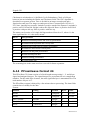
About this document
Rev
Date
Written by
Checked by
Approved by
Rev. 1
2010-02-24
FOS
FOS
FOS
FOS
First issue of this manual
Rev. 2
2010-06-25
Description of serial port extender and minor changes in the text
Copyright
© 2010 Kongsberg Seatex AS. All rights reserved. No part of this work covered by the
copyright hereon may be reproduced or otherwise copied without prior permission from
Kongsberg Seatex AS.
Disclaimer
The information contained in this document is subject to change without prior notice.
Kongsberg Seatex AS shall not be liable for errors contained herein or for incidental or
consequential damages in connection with the furnishing, performance, or use of this
document.
II
M300-62/rev.2
Installation Manual
Table of contents
1
PRODUCT DESCRIPTION ................................................... 1
1.1
Purpose and application ...........................................................................................1
1.2
System components..................................................................................................1
2
TECHNICAL SPECIFICATIONS ........................................... 5
2.1
Performance data......................................................................................................5
2.2
Physical dimensions .................................................................................................5
2.2.1 Processing Unit ......................................................................................................... 5
2.2.2 HMI Unit .................................................................................................................. 5
2.2.3 Monitor, 17-inch LCD .............................................................................................. 6
2.2.4 MRU Unit ................................................................................................................. 6
2.2.5 MRU Wall Mounting Bracket .................................................................................. 6
2.2.6 MRU Junction Box ................................................................................................... 6
2.2.7 Antenna Bracket ....................................................................................................... 7
2.2.8 GNSS antenna........................................................................................................... 7
2.2.9 Cabinet ...................................................................................................................... 7
2.3
Power .......................................................................................................................7
2.3.1 Processing Unit ......................................................................................................... 7
2.3.2 HMI Unit .................................................................................................................. 8
2.3.3 Monitor, 17-inch LCD .............................................................................................. 8
2.3.4 MRU ......................................................................................................................... 8
2.3.5 GNSS antenna........................................................................................................... 8
2.4
Environmental ..........................................................................................................8
2.4.1 Processing Unit ......................................................................................................... 8
2.4.2 HMI Unit .................................................................................................................. 9
2.4.3 Monitor, 17-inch LCD .............................................................................................. 9
2.4.4 MRU Unit ................................................................................................................. 9
2.4.5 GNSS antenna........................................................................................................... 9
2.5
External interfaces..................................................................................................10
2.5.1 Processing Unit ....................................................................................................... 10
2.5.2 HMI Unit ................................................................................................................ 10
2.5.3 MRU Unit ............................................................................................................... 10
M300-62/rev.2
III
Seapath 320
2.6
Product safety .........................................................................................................10
2.6.1 Processing Unit ....................................................................................................... 10
2.7
Radio frequencies ...................................................................................................11
2.7.1 GNSS antenna......................................................................................................... 11
2.7.2 GNSS receiver ........................................................................................................ 11
2.8
Data outputs ...........................................................................................................11
2.8.1 Processing Unit ....................................................................................................... 11
2.9
Data inputs .............................................................................................................12
2.9.1 Processing Unit ....................................................................................................... 12
2.10 Compass safe distance ...........................................................................................12
2.10.1 Processing Unit ....................................................................................................... 12
2.11 Cables .....................................................................................................................12
2.11.1 MRU cable .............................................................................................................. 12
2.11.2 Processing Unit to MRU Junction Box cable ......................................................... 12
2.11.3 GNSS antenna cables (Coax).................................................................................. 13
2.12 Interfaces Processing Unit .....................................................................................14
2.12.1 RS-422 A and B signal definition ........................................................................... 15
2.12.2 Pin layout ................................................................................................................ 15
2.12.3 LED indicators Processing Unit ............................................................................. 21
2.12.4 MRU to Processing Unit cable wiring .................................................................... 22
2.13 Interfaces HMI Unit ...............................................................................................23
2.13.1 Pin layout ................................................................................................................ 24
2.13.2 LED indicators HMI Unit ....................................................................................... 25
3
INSTALLATION................................................................ 27
3.1
Logistics .................................................................................................................27
3.2
Location of the system parts ..................................................................................27
3.2.1 GNSS antennas ....................................................................................................... 28
3.2.2 MRU 5 .................................................................................................................... 29
3.2.3 Processing Unit ....................................................................................................... 30
3.2.4 HMI Unit ................................................................................................................ 30
3.2.5 Monitor ................................................................................................................... 30
3.3
Survey of sensors on vessels ..................................................................................31
3.3.1 Vessel reference system .......................................................................................... 31
IV
M300-62/rev.2
Installation Manual
3.3.2 MRU ....................................................................................................................... 31
3.3.3 GNSS antennas ....................................................................................................... 32
3.3.4 Gyro ........................................................................................................................ 32
3.3.5 Survey accuracy ...................................................................................................... 32
3.3.6 Cabinet mounting ................................................................................................... 33
3.4
Installation procedures ...........................................................................................33
3.4.1 Mechanical installation ........................................................................................... 33
3.4.2 Electrical installation .............................................................................................. 39
3.4.3 Setup of configuration parameters .......................................................................... 42
3.4.4 Calibration .............................................................................................................. 43
4
CONFIGURATION ............................................................ 51
4.1
Starting the system .................................................................................................51
4.2
System configuration .............................................................................................51
4.2.1 System modes ......................................................................................................... 51
4.3
NavEngine configuration .......................................................................................52
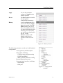
4.4
Standard configuration ...........................................................................................52
4.4.1 Vessel configuration ............................................................................................... 54
4.4.2 GNSS configuration ............................................................................................... 58
4.4.3 DGNSS configuration............................................................................................. 61
4.4.4 MRU configuration................................................................................................. 61
4.4.5 Monitoring points ................................................................................................... 66
4.4.6 Communication interface........................................................................................ 70
4.4.7 Data pool................................................................................................................. 79
M300-62/rev.2
V
Seapath 320
4.5
Configuration backup .............................................................................................79
4.6
SRRD update..........................................................................................................80
5
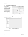
DRAWINGS ..................................................................... 83
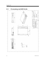
5.1
Processing and HMI Units .....................................................................................84
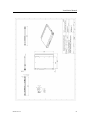
5.2
Antenna bracket .....................................................................................................86
5.3
MRU and mounting bracket ...................................................................................87
5.4
MRU junction box .................................................................................................89
5.5
GNSS antenna mechanical drawings .....................................................................90
5.6
6 U cabinet dimensions ..........................................................................................91
APPENDIX A OUTPUT PROTOCOLS ....................................... 93
A.1 NMEA format ........................................................................................................93
A.2 Binary format 3 ......................................................................................................96
A.3 Simrad EM3000 format 6 ......................................................................................97
A.4 Calibration format ..................................................................................................98
A.5 Echo sounder format 9 ...........................................................................................99
A.6 RDI ADCP format 10 ..........................................................................................100
A.7 Binary format 11 ..................................................................................................100
A.8 Lehmkuhl gyro repeater format 12 ......................................................................102
A.9 1PPS time tag, NMEA ZDA message .................................................................102
A.10 1PPS time tag, Trimble compatible .....................................................................103
A.11 Atlas Fansweep format 16....................................................................................103
A.12 Echo sounder format 18, TSS1 ............................................................................104
A.13 Binary format 23 ..................................................................................................105
A.14 PFreeHeave format 24 .........................................................................................106
A.15 Cyclic redundancy check algorithm .....................................................................107
APPENDIX B INSTALLATION OF COAX CONNECTORS ON
SUPERFLEX CABLE ............................................................... 109
APPENDIX C GNSS ANTENNA INSTALLATION ..................... 115
APPENDIX D ½" COAX CABLE SPECIFICATION .................. 117
APPENDIX E RG-214 SPECIFICATIONS .............................. 119
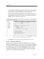
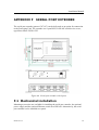
APPENDIX F SERIAL PORT EXTENDER ................................ 121
F.1
VI
Mechanical installation ........................................................................................121
M300-62/rev.2
Installation Manual
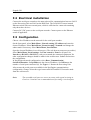
F.2
Electrical installation............................................................................................122
F.3
Configuration .......................................................................................................122
APPENDIX G FREE AND OPEN SOURCE SOFTWARE............. 123
G.1 GNU General Public License ...............................................................................123
G.2 GNU Lesser General Public License ...................................................................126
G.3 BSD License ........................................................................................................129
G.4 NTP License .........................................................................................................129
G.5 Berkeley DB License ...........................................................................................130
G.6 OpenSSL License .................................................................................................130
G.7 WU-FTPD Software License ...............................................................................132
G.8 Ubuntu licensing ..................................................................................................132
M300-62/rev.2
VII
Seapath 320
List of figures
Figure 1 Standard system for 19-inch rack mounting ....................................................... 2
Figure 2 Rear panel of Processing Unit without chord anchorage .................................. 14
Figure 3 Connector board ................................................................................................ 16
Figure 4 External alarm connection diagram .................................................................. 18
Figure 5 Front panel of Processing Unit.......................................................................... 21
Figure 6 Front view of HMI Unit .................................................................................... 25
Figure 7 Location of system parts ................................................................................... 28
Figure 8 Dimensional drawing for antenna holder .......................................................... 34
Figure 9 Top view of Antenna Bracket ........................................................................... 35
Figure 10 Different components for mounting of Antenna Bracket ............................... 35
Figure 11 Side view of GNSS antenna installation ......................................................... 36
Figure 12 Recommended orientation of the MRU mounting bracket ............................. 37
Figure 13 Wall mounting of bracket with MRU connector pointing down .................... 37
Figure 14 Sticker (4) shall indicate actual MRU mounting orientation within bracket .. 38
Figure 15 MRU junction box mounting .......................................................................... 39
Figure 16 Offset vectors between the different components ........................................... 43
Figure 17 Page 1 of GNSS antenna calibration ............................................................... 46
Figure 18 Page 2 of antenna calibration wizard .............................................................. 47
Figure 19 Page 3 of antenna calibration wizard .............................................................. 47
Figure 20 Page 4 of antenna calibration wizard .............................................................. 48
Figure 21 Alignment of MRU yaw axis to vessel longitudinal axis ............................... 49
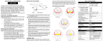
Figure 22 Value of roll error as a function of vessel pitch angle, displayed at 0.5°, 1°
and 1.5° MRU yaw misalignment ..................................................................................... 50
Figure 23 Change system mode menu............................................................................. 51
Figure 24 NavEngine configuration ................................................................................ 52
Figure 25 NavEngine Configuration view ...................................................................... 52
Figure 26 History button ................................................................................................. 53
Figure 27 Configuration manager.................................................................................... 53
Figure 28 Vessel geometry view ..................................................................................... 54
Figure 29 Example GA drawing of multi-purpose vessel ............................................... 56
Figure 30 Example of vessel shape in user text file ........................................................ 56
Figure 31 Example vessel shown in Vessel Geometry view ........................................... 57
VIII
M300-62/rev.2
Installation Manual
Figure 32 Vessel Description view.................................................................................. 57
Figure 33 GNSS sensor geometry configuration view .................................................... 59
Figure 34 GNSS Processing settings view ...................................................................... 60
Figure 35 GNSS Attitude Processing view ..................................................................... 60
Figure 36 SBAS tracking view ........................................................................................ 61
Figure 37 MRU geometry view ....................................................................................... 62
Figure 38 Step 1 of MRU axis orientation ...................................................................... 63
Figure 39 Step 2 of Manual input of mounting angles .................................................... 63
Figure 40 Step 3 of Manual input of MRU mounting angles .......................................... 64
Figure 41 Heave filter view ............................................................................................. 66
Figure 42 Monitoring points view ................................................................................... 67
Figure 43 Add a new monitoring point ........................................................................... 68
Figure 44 New monitoring point, MP4, added to list ...................................................... 69
Figure 45 Renaming of monitoring point to preferred name........................................... 69
Figure 46 Input/output view before interface details are added ...................................... 70
Figure 47 Input/Output list view with configuration details ............................................ 71
Figure 48 Configuration details view .............................................................................. 71
Figure 49 I/O properties view when serial interface is selected ...................................... 72
Figure 50 I/O properties view when net interface is selected.......................................... 73
Figure 51 Interface set to TelegramOut ........................................................................... 73
Figure 52 Telegram output options ................................................................................. 74
Figure 53 Available NMEA telegrams ............................................................................ 75
Figure 54 Gyro properties ............................................................................................... 76
Figure 55 Telegram timing view ..................................................................................... 76
Figure 56 DGNSS link properties ................................................................................... 77
Figure 57 Analog output properties ................................................................................. 78
Figure 58 Data Pool configuration view ......................................................................... 79
Figure 59 Configuration Copier ...................................................................................... 80
Figure 60 Serial port extender with 8-ports ................................................................... 121
M300-62/rev.2
IX
Seapath 320
List of tables
Table 1 GNSS antenna cable specification ..................................................................... 13
Table 2 Connectors at rear of Processing Unit ................................................................ 15
Table 3 Connectors at front of Processing Unit .............................................................. 15
Table 4 Pin layout of Com 1 and Com 2 ......................................................................... 16
Table 5 Pin layout of Com 9 through Com 14 ................................................................ 17
Table 6 Pin layout of PPS port ........................................................................................ 17
Table 7 Pin layout of Alarm ............................................................................................ 18
Table 8 Pin layout of Analog Out.................................................................................... 19
Table 9 Pin layout of MRU ............................................................................................. 20
Table 10 Pin layout for LAN 1 Ethernet ports ................................................................ 20
Table 11 Pin layout for LAN 2, 3 and 4 Ethernet ports................................................... 21
Table 12 MRU to Processing Unit cable wiring.............................................................. 23
Table 13 Connectors at rear of HMI Unit ....................................................................... 24
Table 14 Connectors at front of HMI Unit ...................................................................... 24
Table 15 Pin layout for HMI Unit Ethernet ports............................................................ 24
X
M300-62/rev.2
Installation Manual
Abbreviations
AP
Aft Perpendicular. The vertical intersection of the design
waterline at the stern, alternatively the centerline of the rudder
stock.
BL
Base Line. Is the same as the keel for a vessel with horizontal
keel line.
CEP
Circular Error Probability
CG
Centre of gravity. The mass centre of a vessel. This is normally
the location with least linear acceleration, and hence the best
location for measurements of roll and pitch.
CL
Centre Line. Is the longitudinal axis along the center of the
ship.
DGLONASS
Differential GLONASS
DGNSS
Differential Global Navigation Satellite System
DGPS
Differential GPS
ED50
European Datum of 1950
EGNOS
European Geostationary Navigation Overlay System (SBASEuropa)
EPE
Estimated Position Error
GLONASS
Global Navigation Satellite System
GNSS
Global Navigation Satellite System
GPS
Global Positioning System
GPS Time
The time in the GPS system. The GPS time is within UTC time
±180 nsec (95 per cent) plus leap second.
GUI
Graphical User Interface
HMI
Human Machine Interface
HP
High Precision
IALA
International Association of Lighthouse Authorities
IMO
International Maritime Organization
IMU
Inertial Measurement Unit
LGND
Logic Ground
MP
Monitoring Point
M300-62/rev.2
XI
Seapath 320
MRU 5
Motion Reference Unit, model 5. This is the IMU within the
Seapath measuring dynamic linear motion and attitude. A
MRU consists of gyros and accelerometers.
NMEA
National Marine Electronics Association. NMEA 0183 is a
standard for interchange of information between navigation
equipment.
NRP
Navigation Reference Point. The reference point for all
measurements in Seapath. The recommended used NR is the
vessel CG or rotation center.
PGND
Power Ground
PPS
One Pulse Per Second
PRN
Pseudorandom Noise
RMS
Root Mean Square
RTCM
Radio Technical Commission of Maritime Services
SL
Speed Along Ship
SNR
Signal/Noise Ratio
SOG
Speed Over Ground
SBAS
Satellite Based Augmentation System
SRRD
Seatex Rescue and Restore Disk
ST
Speed Transverse Ship
SW
Software
UTC
Universal Time Co-ordinated. This is the official time in the
world and has replaced GMT (Greenwich Mean Time) as the
official time.
UTM
Universal Transverse Mercator
WAAS
Wide Area Augmentation System (SBAS-USA/Canada)
WEEE
Waste Electrical and Electronic Equipment
WGS84
World Geodetic System of 1984
XII
M300-62/rev.2
Installation Manual
Terminology
Alignment
Is the process of adjusting the current internal navigation frame
in the instrument to the true external frame.
Antenna bracket
Is the arrangement for mounting the GPS antennas
Antenna holder
Is the arrangement on board the vessel for mounting the
antenna bracket to.
Attitude
The orientation relative to the vertical axis of a vehicle.
Heading is not included. If heading is included, the word
"orientation" is used for the vehicle.
Beam
The maximum width of the vessel at Main Deck level (B. mld)
Heading
The direction of the main axis (bow direction) of the vehicle as
opposed to course, which is the direction of motion of the
vehicle. Yaw angle as defined here is the same as heading.
Heave
The vertical dynamic motion of a vehicle and defined positive
down. Heave position and velocity are dynamic motion
variables oscillation around a mean value, typically zero.
Height
The height in the Seapath product is defined as the vertical
position relative to the WGS84 datum (rotational ellipsoid).
Host system
In this manual defined as Navigation computers, Dynamic
Positioning Systems, etc., receiving data from Seapath.
Origin
The zero point in the coordinate system. The origin is the
intersection point between AP, BL and CL.
P-axis
This axis is fixed in the vehicle, and points in the starboard
direction horizontally when the roll angle is zero. Positive
rotation about this axis is bow of the vehicle up.
Pitch
A rotation about the pitch axis is positive when the bow moves
up. Normally, pitch means the dynamic pitch angle motions.
R-axis
This axis is fixed in the vehicle, and points in the forward
direction horizontally when the pitch angle is zero. Positive
rotation about this axis is starboard side of the vehicle down.
Roll
A rotation about the roll axis is positive when starboard side of
the vehicle moves down. Normally, roll means the dynamic roll
angle motion.
Starboard
When looking in the bow direction of a vehicle, this is the right
hand side of the vehicle.
Surge
The alongship dynamic motion of a vehicle and defined
positive forward.
M300-62/rev.2
XIII
Seapath 320
Sway
The athwartship dynamic motion of a vehicle and defined
positive starboard.
Y-axis
This axis is fixed in the vehicle and points in the downward
direction when the vehicle is aligned horizontally. Positive
rotation about this axis is turning the bow of the vehicle to
starboard.
Yaw
A rotation about the vertical axis is positive when turning
Eastward (Clockwise) when the vehicle cruises in North
direction. Normally, yaw means the dynamic yaw motion.
References
[1]
[2]
[3]
[4]
XIV
M300-52, User Manual, Seapath 320
NMEA 0183 Standard for Interfacing Marine Electronic Devices, Version
3.0
RTCM Recommended Standards for Differential Navstar GPS/GLONASS
services, Version 2.3
GPS-702GG and GPS-701GG User Guide, OM20000095 Rev 1, NovAtel
Inc. January 23, 2006
M300-62/rev.2
Installation Manual
Health, environment and safety warnings
All electrical and electronic components have to be disposed
of separately from the municipal waste stream via designated
collection facilities appointed by the government or local
authorities. The correct disposal and separate collection of
your old appliance will help prevent potential negative
consequences for the environment and human health. It is a
precondition for reuse and recycling of used electrical and
electronic equipment. For more detailed information about
disposal of your old appliance, please contact your local
authorities or waste disposal service.
Until further notice is given regarding reuse, disassembly or
disposal, the equipment at end-of-life, could be returned to
Kongsberg Seatex AS if there is no local WEEE collection.
The equipment is marked with this pictogram.
Restrictions in export
Export of the MRU 5 component within the Seapath product to other countries than EU
countries or Argentina, Australia, Canada, Iceland, Japan, New Zealand, Switzerland,
South-Korea, Turkey, Ukraine and USA, requires an export license.
Notice to Importer: The MRU product specified in this document has been shipped from
Norway in accordance with The Ministry of Foreign Affairs' Official Notification on
Export Control and may be subject to restrictions if re-exported from your country.
Restrictions in guarantee
The liability of Kongsberg Seatex is limited to repair of the Seapath system only under
the given terms and conditions stated in the sales documents. Consequential damages
such as customer's loss of profit or damage to other systems traceable back to Seapath
malfunction are excluded. The warranty does not cover malfunctions of the Seapath
resulting from the following conditions:
1
The MRU is not shipped in the original transport box.
2
The MRU has been exposed to extreme shock and vibrations.
3
The MRU housing has been opened by the customer in an attempt to carry out repair
work.
4
Over-voltage or incorrect power connection.
5
Shorting of GNSS antenna cable during operation of the Seapath systems.
M300-62/rev.2
XV
Seapath 320
Restrictions in use
The Seapath function is based on GNSS signals and requires free sight to the sky,
minimum four visible satellites, PDOP value less than 6 and otherwise normal
conditions to operate. It is designed for use on board marine surface operated vehicles
with linear acceleration less than ±30 m/s2 (±3g) and an angular rate range less than
±150°/s.
Only relative dynamic heave position is calculated.
XVI
M300-62/rev.2
Installation Manual
1 PRODUCT DESCRIPTION
This manual describes a typical survey installation of the Seapath 320 system on a
vessel. For all other information about the Seapath, please consult the User Manual,
reference [1].
1.1
Purpose and application
Seapath 320 combines the latest achievements in advanced GPS and GLONASS
technology aided by a high performance IMU (Inertial Measurement Unit). The
integration of GPS/GLONASS and an IMU is ideal due to the combination of
complementary physical qualities into a tightly integrated solution.
1.2
System components
The system is supplied with the following parts:
Seapath 320 Processing Unit including processing software. Part no. M300-23.
Antenna Bracket in aluminium, 2.5-metre baseline. Part no. M320-21.
Antennas, two GPS/GLONASS L1&L2 antennas. Part no. G060-24N.
Cable, Interconnection, N-M/N-F, four of 1 m. Part no. G071-91. Two as adapter
cable from GNSS antenna connector to cable and two as adapter cable for GNSS
antenna cable to PU (N to N).
Seapath HMI Unit with operator software. Part no. M300-04.
Cable for power, Processing and HMI Unit, two of 2.5 m. Part no. G032-28.
Monitor, 17" standard LCD, table mount. Part no. G060-32.
Keyboard (US layout). Part no. G062-11.
PC mouse. Part no. G062-16.
MRU 5 sensor. Part no. MRU-5.
MRU wall mounting bracket. Part no. MRU-M-MB3.
MRU junction box for flexible connection of MRU to Seapath. Part no. MRU-E-JB1.
Cable, heavy duty screened cable with 14 twisted pairs. Part no. MRU-E-CS1.
MRU transportation box. Part no. MRU-M-SC1.
Seapath 320 Product Manuals. Part no. M300-72.
M300-62/rev.2
1
Seapath 320
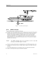
Figure 1 Standard system for 19-inch rack mounting
In addition to the above delivered parts, the following is needed:
A 19-inch rack for mounting of the Processing Unit.
A 19-inch rack for mounting of the HMI Unit.
GNSS antenna cables and the cable between the Processing Unit and the MRU
junction box.
DGPS/DGLONASS corrections on one or more serial lines for improved position
accuracy (recommended).
Additional cables for input of DGPS/DGLONASS corrections, and for output lines
to external equipment.
Devices for reference measurements of roll, pitch and heading (for calibration).
General arrangement drawings of the ship should be acquired to simplify determination
of offsets between the GNSS antennas, the MRU, the Navigation Reference Point
(NRP) and the different monitoring points. Locations for the various parts of the system
must be decided and mounting arrangement for the Antenna Bracket and sufficient
lengths of cable made available.
An external heading reference, for example a surveyed quay, is required for heading
calibration. Survey equipment should be made available for determination of the
alignment offset in roll, pitch and yaw.
2
M300-62/rev.2
Installation Manual
The MRU unit is shipped in a specially designed transportation container. Keep the
MRU in this container until ready to install the unit in the mounting bracket.
Note
M300-62/rev.2
After the installation, please save the transportation container. To
maintain warranty validity, the MRU must be shipped in this container for
service or repair.
3
Seapath 320
4
M300-62/rev.2
Installation Manual
2 TECHNICAL SPECIFICATIONS
2.1
Performance data
Roll and pitch accuracy for ±5° amplitude .................................................. 0.02° RMS (*)
Heading accuracy with 2.5 metre antenna baseline .........................................0.075° RMS
Heading accuracy with 4 metre antenna baseline ..............................................0.05° RMS
Scale factor error in roll, pitch and heading ................................................... 0.08 % RMS
Heave accuracy (real-time output) ................................ 5 cm or 5 % whichever is highest
Heave motion periods (real-time output).................................................... 0 to 20 seconds
Heave accuracy (delayed signal, PFreeHeave™) ........... 3 cm or 3 % whichever is highest
Heave motion periods (delayed signal, PFreeHeave®)............................... 0 to 50 seconds
Position accuracy with DGPS/GLONASS .......................... 0.5 m RMS or 1 m 95 % CEP
Position accuracy with SBAS .............................................. 0.5 m RMS or 1 m 95 % CEP
Position accuracy with RTK (floating ambiguity mode) ....................................................
...................................................................................... 0.15 m RMS or 0.35 m 95 % CEP
Velocity accuracy .................................................... 0.03 m/s RMS or 0.07 m/s 95 % CEP
The performance figures are valid with a minimum of four visible satellites, HDOP less
than 2.5, PDOP less than 6, high quality DGPS corrections, correctly measured offsets
and otherwise normal conditions. Excessive multipath, GNSS signal obstructions or
interference may reduce the performance.
2.2
Physical dimensions
2.2.1
Processing Unit
Height ........................................................................................................... 88.1 mm (2U)
Width ............................................................................................................ 485 mm (19")
Depth ..................... Min 325 mm (excluding connectors on rear panel) and max 412 mm
Weight .......................................................................................................................5.4 kg
Colour ............................................................................................. Front anodized natural
2.2.2
HMI Unit
Height ......................................................................................................... 43.65 mm (1U)
Width ............................................................................................................ 485 mm (19")
M300-62/rev.2
5
Seapath 320
Depth ..................... Min 325 mm (excluding connectors on rear panel) and max 405 mm
Weight .......................................................................................................................3.8 kg
Colour ............................................................................................. Front anodized natural
2.2.3
Monitor, 17-inch LCD
Type ......................................................................................... Samsung SyncMaster 710n
Width ..................................................................................................................... 380 mm
Height .................................................................................................................... 383 mm
Depth ..................................................................................................................... 170 mm
Weight .......................................................................................................................3.8 kg
Colour ........................................................................................................Black and silver
2.2.4
MRU Unit
Type .........................................................................................................................MRU 5
Height ...................................................................................................... 204 mm (8.032")
Diameter .................................................................................................. 105 mm (4.134")
Weight .......................................................................................................................2.5 kg
Colour .......................................................................................................................... Blue
Connector ........................................................ Souriau 851-36RG 16-26S50 (MIL. spec.)
2.2.5
MRU Wall Mounting Bracket
Type ............................................................................................................. MRU-M-MB3
Length .................................................................................................................... 265 mm
Width ..................................................................................................................... 119 mm
Height .................................................................................................................... 119 mm
Weight .......................................................................................................................1.6 kg
Colour ........................................................................................................................ Black
Material................................................................................................................... POM-H
2.2.6
MRU Junction Box
Type ................................................................................................................ MRU-E-JB1
Length .................................................................................................................... 226 mm
Width ..................................................................................................................... 126 mm
Height ...................................................................................................................... 90 mm
6
M300-62/rev.2
Installation Manual
Weight .......................................................................................................................2.0 kg
Colour ........................................................................................................................ Black
Material............................................................................................................. Aluminium
Enclosure protection ................................................................................................... IP-65
2.2.7
Antenna Bracket
Type ...................................................................................................................... M320-21
Length .................................................................................................................. 2560 mm
Width ....................................................................................................................... 75 mm
Height ...................................................................................................................... 40 mm
Weight .......................................................................................................................6.6 kg
Colour ........................................................................................................Grey RAL 7035
2.2.8
GNSS antenna
Type ................................................................................................. Novatel GPS-702-GG
Height ................................................................................................................... 69.1 mm
Diameter ................................................................................................................ 185 mm
Weight .......................................................................................................................0.5 kg
Colour ........................................................................................................................ White
The GNSS antenna is a right-hand circular polarised L-band antenna with an integral
low-noise amplifier. The internal thread is 5/8 x 11 (standard marine mount).
2.2.9
Cabinet
Height .................................................................................................................... 390 mm
Depth ..................................................................................................................... 600 mm
Width ..................................................................................................................... 553 mm
Depth with keyboard extended .............................................................................. 770 mm
Recommended free space from wall ....................................................................... 20 mm
2.3
Power
2.3.1
Processing Unit
Voltage ..................................................................................... 100 - 240 V AC, 50/60 Hz
M300-62/rev.2
7
Seapath 320
Power consumption ......................................................................................... Max. 75 W1
Batteries .............................................................. None, connection to UPS recommended
2.3.2
HMI Unit
Voltage ..................................................................................... 100 - 240 V AC, 50/60 Hz
Power consumption ...........................................................................................Max. 40 W
Batteries .............................................................. None, connection to UPS recommended
2.3.3
Monitor, 17-inch LCD
Voltage ................................................................................... 100 to 240 V AC, 50/60 Hz
Power consumption ................................................................................ 23 Watts (typical)
2.3.4
MRU
Voltage ............................................................................. 24 V DC, from Processing Unit
2.3.5
GNSS antenna
Voltage ............................................................................... 5 V DC, from Processing Unit
2.4
Environmental
2.4.1
Processing Unit
Enclosure material ............................................................................................ Aluminium
Operating temperature range .................................................................. -15 °C to +55 °C2
Recommended operating temperature ....................................Room temperature (+20 °C)
Storage temperature ................................................................................. -20 °C to +70 °C
Operating humidity ................................................................. Max. 95 % non-condensing
Storage humidity ........................................................................................ Less than 55 %
Ingress protection front............................................................................................... IP 42
Ingress protection rear ................................................................................................ IP 21
1
2
8
With MRU connected.
Operating temperature up to +55 ºC for 10 hours.
M300-62/rev.2
Installation Manual
2.4.2
HMI Unit
Enclosure material ............................................................................................ Aluminium
Operating temperature range .................................................................. -15 °C to +55 °C3
Recommended operating temperature ....................................Room temperature (+20 °C)
Storage temperature ................................................................................. -20 °C to +70 °C
Operating humidity ................................................................. Max. 95 % non-condensing
Storage humidity ........................................................................................ Less than 55 %
Ingress protection front............................................................................................... IP 42
Ingress protection rear ................................................................................................ IP 21
2.4.3
Monitor, 17-inch LCD
Operating temperature range ............................................................................ 5 to +40 °C
Relative humidity .............................................................................................. 20 to 80 %
2.4.4
MRU Unit
Enclosure material ............................................................................. Anodised aluminium
Enclosure protection ................................................................................................... IP-66
Operating temperature range ........................................................................... -5 to +55 °C
Operating humidity (max) ......................................................................... Sealed, no limit
Storage temperature range ............................................................................. -20 to +70 °C
Storage humidity ....................................................................................... Sealed, no limit
Max allowed vibration operational (10 – 2000 Hz continuous) .............................0.5 m/s2
Max allowed vibration non-operational (0 – 200 Hz continuous)...........................20 m/s2
Max shock non-operational (10 ms peak) ...........................................................1000 m/s2
2.4.5
GNSS antenna
Operating temperature range ................................................................... -40 °C to +85 °C
Ingress protection ..................................................................................... IP X6 and IP X7
3
Operating temperature up to +55 ºC for 10 hours.
M300-62/rev.2
9
Seapath 320
2.5
External interfaces
2.5.1
Processing Unit
Serial ports ........................................... 6 non-dedicated isolated ports, RS-232 or RS-422
................................................ Isolated Com1 and Com2, 9 pin DSub, RS-232 or RS-422
Baud rate ....................................................................................... Up to 115 200 bytes/sec
LAN ........................................................................................................... 4 Ethernet ports
USB .................................................................................... 3 ports, 1 in front and 2 in rear
Data output rate ............................................................................................. Up to 200 Hz
Timing accuracy .......................................................................................................... 1 ms
Data delay ......................................... All data in real-time (0 ms) plus transmission delay
1PPS signal accuracy .............................................................................................220 nsec
Analog outputs..................................................... 3 user configurable channels, ±10 Volts
2.5.2
HMI Unit
USB .................................................................................... 3 ports, 1 in front and 2 in rear
LAN ................................................................................................. 1 Ethernet port in rear
2.5.3
MRU Unit
Serial ports .......................................................................................... 1 RS-232 or RS-422
Digital output variables ......................................................................................... Max. 16
Data output rates ............................................................................................. Max. 100 Hz
Timing ...................................................................................................................... < 1 ms
2.6
Product safety
2.6.1
Processing Unit
Electrical safety .......................................................................... IEC 60950-1/EN60950-1
Electromagnetic compatibility (immunity/radiation) ........................ IEC 60945/EN60945
Vibration ............................................................................................ IEC 60945/EN60945
10
M300-62/rev.2
Installation Manual
2.7
Radio frequencies
2.7.1
GNSS antenna
L1 ......................................................................................................... 1588.5 ± 23.0 MHz
L2 ......................................................................................................... 1236.0 ± 18.3 MHz
LNA gain (typical) .................................................................................................... 27 dB
2.7.2
GNSS receiver
GPS L1 ......................................................................................................... 1575.42 MHz
Glonass L1 ...........1602.0 MHz for Fk=0 where k=(-7 to +13) channel spacing 562.5kHz
2.8
Data outputs
2.8.1
Processing Unit
Message format ......................................................................NMEA 0183 v. 3.0 of type:
ZDA, GGA, GLL, VTG, HDT, GST, GSA and GRS
NMEA proprietary PSXN, 20, PSXN, 21, PSXN, 22 and PSXN, 23
............................................. Simrad EM1000 (Simrad EM950 and EM1000 compatible)
...................................................................................................... Seapath binary format 3
................................. Simrad EM3000 (Simrad EM3000, EM300 and HiPap compatible)
............................................................................................................... Calibration format
........................................................................................................... Echo sounder format
.............................................RD Instrument ADCP proprietary NMEA format, "PRDID"
.................................................................................................... Seapath binary format 11
.......................................................................................... Lehmkuhl gyro repeater format
................................................................................ 1PPS time tag, NMEA ZDA message
.................................................................... 1PPS time tag, Trimble compatible messages
........................................................................................................Atlas Fansweep format
........................................................................................... Echo sounder format 18, TSS1
................................................................................................. RTCM v3, raw GPS output
.................................................................................................... Seapath binary format 23
............................................................................................................. PFreeHeave format
M300-62/rev.2
11
Seapath 320
2.9
Data inputs
2.9.1
Processing Unit
DGPS corrections ................................................................. RTCM-SC104 v. 2.2 and 2.3
...................................................................................................................... Trimble CMR
DGLONASS corrections ................................................................... RTCM-SC104 v. 2.2
Gyro compass ............................................................. NMEA 0183 HEHDT and HEHRC
............................................................................................. Robertson LR22 BCD format
2.10
Compass safe distance
2.10.1 Processing Unit
Standard compass (mounted in 6U cabinet) ...............................................................2.6 m
Note
2.11
If the Processing Unit is not marked with a compass safe distance label,
the unit shall be placed five metres from both the steering compass and the
standard compass.
Cables
2.11.1 MRU cable
Type ................................................................................................................MRU-E-CS1
............................................................................Heavy duty screened, 14 x 2 x 0.25 mm2
Length ............................................................................................................................3 m
Diameter ............................................................................................................... 13.5 mm
Weight ................................................................................................................ 0.27 kg/m
Flame retardation ................................................................................................ IEC 332-1
Insulation ................................................................................................................... ETFE
Screen ................................................................................................................... Cu-braid
2.11.2 Processing Unit to MRU Junction Box cable
Type ........................................................................................... LAMAC, 4 x 2 x 0.5 mm2
Maximum length .......................................................................................................100 m
Diameter .................................................................................................................. 10 mm
12
M300-62/rev.2
Installation Manual
Flame retardation ............................................................................................ IEC 332-3/A
2.11.3 GNSS antenna cables (Coax)
Type ................................................................................................. ½"-Superflex 50 BHF
Attenuation ................................................................................ 14 dB/100 m (at 1.6 GHz)
Maximum length (each cable) ...................................................................................100 m
Diameter ............................................................................................................... 13.2 mm
Minimum bend radius.............................................................................................. 32 mm
Flame retardation ................................................... CATV, UL1581, IEC 332-3, IEEE383
Coax connectors ..................................................................... Huber+Suhner 11 N-50-9-9
If the antenna cables are not delivered by Kongsberg Seatex, make sure that the cables
meet the following electrical specifications:
Insertion loss (max.)
15 dB (at 1.6 GHz)
Characteristic impedance
50 Ohm (nominal)
DC resistance (max.)
0.5 Ohm ground braid and centre conductor
Table 1 GNSS antenna cable specification
The antenna connectors on the Processing Unit are of N-type male. On the GNSS
antennas both TNC-type female and N-type female are available. Optionally, an
interconnection cable for transfer of connector type from TNC on the antenna to N-type
on the antenna cable, can be delivered.
M300-62/rev.2
13
Seapath 320
2.12
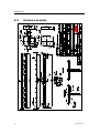
Interfaces Processing Unit
The rear panel of the Processing Unit contains communication interface ports for
interfacing to external equipment. In addition, a USB and a LAN port are situated at the
front together with the power switch.
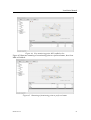
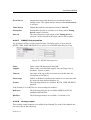
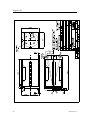
Figure 2 Rear panel of Processing Unit without chord anchorage
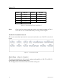
Connector
Type
Connected to
GNSS 1
N connector 50 Ohm female
GNSS antenna
GNSS 2
N connector 50 Ohm female
GNSS antanna
IALA
N connector 50 Ohm female
Not in use
LAN 2
RJ-45
User configurable
USB 2
USB
User configurable
USB 3
USB
User configurable
LAN 3
RJ-45
Not in use
LAN 4
RJ-45
User configurable
Mouse
PS/2
Mouse
Keyboard
PS/2
Keyboard
COM 1
9 pin DSub male, RS-232
User configurable
COM 2
9 pin DSub male, RS-232
User configurable
VGA
HD15 female
Monitor
COM 9
5 pins terminal, RS-232/422
User configurable
COM 10
5 pins terminal, RS-232/422
User configurable
COM 11
5 pins terminal, RS-232/422
User configurable
COM 12
5 pins terminal, RS-232/422
User configurable
COM 13
5 pins terminal, RS-232/422
User configurable
COM 14
5 pins terminal, RS-232/422
User configurable
14
M300-62/rev.2
Installation Manual
Connector
Type
Connected to
ALARM
3 pins terminal, relay
External alarm system
MRU
10 pins terminal, RS-422
MRU5 or MRU5+
IMU
10 pins terminal
Not in use
1PPS
6 pins terminal
External equipment
ANALOG OUT
10 pins terminal
User configurable
ANALOG IN
6 pins terminal
Not in use
115/230VAC
Power
Input of 115/230VAC
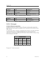
Table 2 Connectors at rear of Processing Unit
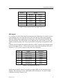
Connector
Type
Connected to
LAN 1
RJ-45
User configurable
USB 1
USB
User configurable
Table 3 Connectors at front of Processing Unit
Note
All numbering of the pins on the terminals goes from left (no. 1) to right
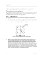
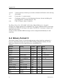
2.12.1 RS-422 A and B signal definition
According to the following standard the signal state definitions are:
IEC 61162-1. The idle, marking, logical 1, OFF or stop bit states are defined by a
negative voltage on line A with respect to line B. The active, spacing, logical 0, ON
or start bit states are defined by a positive voltage on line A with respect to line B. It
should be noted that the above A with respect to B levels are inverted from the
voltage input/output requirements of standard UARTs and that many line drivers and
receivers provide a logic inversion.
2.12.2 Pin layout
2.12.2.1 COM 1 and 2
Com 1 and Com 2 at the rear of the Processing Unit are 9-pin DSub male and have the
following pin layout.
M300-62/rev.2
15
Seapath 320
Pin no.
RS-232
Pin no.
RS-232
1
DCD1
6
DSR1
2
RXD1
7
RTS1
3
TXD1
8
CTS1
4
DTR1
9
RI1
5
GND
Table 4 Pin layout of Com 1 and Com 2
Note
Com 1 and 2 are not as timing accuracte with regard to timing as Com 9
to 14 and are not recommended used for timing critical outputs.
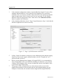
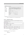
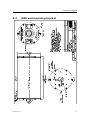
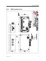
2.12.2.2 Connector board
The screw terminal pin layout on the connector board at the rear of the PU is described
below.
Figure 3 Connector board
Serial lines – Com 9 – Com 14
The system communicates with external equipment through the six RS-232 or RS-422
configurable serial input and output lines.
The configuration of serial lines and their default settings are:
16
M300-62/rev.2
Installation Manual
Pin no.
Signal
RS-422
RS-232
1
RX_A
CTS
2
RX_B
RX
3
GND
GND
4
TX_A
RTS
5
TX_B
TX
Table 5 Pin layout of Com 9 through Com 14
PPS signal
A 1 pulse-per-second (1PPS) signal synchronized with GNSS time is available from the
6 pin terminal at the rear of the Processing Unit. This RS-422 1PPS signal originates
from the GNSS receiver within the Processing Unit. The 1PPS signal is buffered and
fed to the terminal. The 1PPS signal is active high and has a pulse width of 10 ms. The
1PPS is generated exactly once every second with its rising edge synchronised to GPS
time.
Compared to the Seapath 200 models which have a BNC connector this Seapath model
uses a serial signal. Pin no. 1 (TX_A) has a positive edge at the beginning of the pulse
and pin no. 2 (TX_B) has a positive edge at the end of the pulse.
Pin no.
Signal
Direction
1
1PPS TX_A
Output
2
1 PPS TX_B
Output
3
GND isolated
Output
4
GND isolated
Input
5
1PPS RX_A
Input
6
1PPS RX_B
Input
Table 6 Pin layout of PPS port
Synchronized with this signal it is possible to output 1PPS time tag messages from
Seapath. These messages are the 1PPS NMEA ZDA (format no. 13) or the Trimble
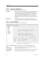
compatible message (format no. 14).
M300-62/rev.2
17
Seapath 320
For description of the format for these messages, see APPENDIX A Output
Protocols.
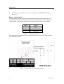
Relay - alarm signal
The Processing Unit has a built-in alarm functionality and can be connected to an
external alarm. An alarm will open the alarm relay, which can be used to trigger an
external alarm. The external alarm can be connected to the Alarm 3 pin terminal.
Pin no.
Signal
1
NC
2
Alarm_Com
3
Alarm_NO
Table 7 Pin layout of Alarm
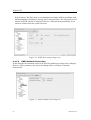
The diagram below shows how an external alarm can be connected to the Processing
Unit ALARM terminal.
Figure 4 External alarm connection diagram
18
M300-62/rev.2
Installation Manual
Analog output
Three analog output channels are available on the Analog Out 10 pin terminal. The
variables available for analog output are roll, pitch, heave and Datawell Hippy
compatible roll and pitch signals. The selection of variable and channel properties is
performed in the operator software.
The pin wiring for the analog outputs is as follows:
Pin no.
Signal
1
GND_Isolated_DAC
2
Analog_Out_Ch2_N
3
Analog_Out_Ch2_P
4
GND_Isolated_DAC
5
Analog_Out_Ch1_N
6
Analog_Out_Ch1_P
7
GND_Isolated_DAC
8
Analog_Out_Ch0_N
9
Analog_Out_Ch0_P
10
GND_Isolated_DAC
Table 8 Pin layout of Analog Out
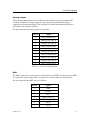
MRU
The MRU connector is used for power and interface to an MRU. Usually when an MRU
is connected to a Processing Unit, a junction box is used to make the wiring easier.
The pin wiring for the MRU port is as follows:
M300-62/rev.2
Pin no.
Signal
1
GND
2
LGND
3
NC
4
MRU_1PPS_N
5
XIN/MRU_1PPS_P
6
TX_A
7
TX_B
19
Seapath 320
Pin no.
Signal
8
RX_A
9
RX_B
10
24V_MRU
Table 9 Pin layout of MRU
IMU
The IMU terminal is not in use in this product.
Analog in
This terminal is not in use in this product.
Ethernet connection
The Processing Unit has the possibility to input and output data on individually
configurable network ports. The format and update rate are configured for each port in
the NavEngine Configuration view.
The Processing Unit has the following LAN and connection possibilities:
LAN 1 in the front. This is primarily a service port and has less capacity (10/100
Mbps) that the other LANs. To connect this LAN to a network, a straight-through
twisted pair (TP) cable with RJ-45 connectors must be used. A straight-through cable
is one where the pins of one connector are connected to the same pins of the other
connector. In special instances a crossover cable instead of a straight-through cable is
needed, for example when connecting a Processing Unit to another Processing Unit.
Below is the pin wiring for the different TP cables:
Straight-through
Crossover
Signal
Pin no.
Pin no.
Signal
Signal
Pin no.
Pin no.
Signal
TX+
1
1
TX+
TX+
1
3
RX+
TX-
2
2
TX-
TX-
2
6
RX-
RX+
3
3
RX+
RX+
3
1
TX+
RX-
6
6
RX-
RX-
6
2
TX-
Table 10 Pin layout for LAN 1 Ethernet ports
The pins 4, 5, 7 and 8 are not used.
20
M300-62/rev.2
Installation Manual
LAN 2, 3 and 4 at the rear. These LANs are of high capacity (10/100/1000 Mbps)
and are of type auto crossover and auto negation. Below is the pin wiring for these
LANs connected to different network capacities:
10/1000 or 100/1000 Mbps Ethernet
1000/1000 Mbps Ethernet
Pin no.
Signal
Description
Pin no.
Signal
Description
1
TX_DA-
Transceive data +
1
BI_DA+
Bi-directional pair +A
2
TX_DA-
Transceive data -
2
BI_DA-
Bi-directional pair -A
3
RX_DB+
Receive data +
3
BI_DB+
Bi-directional pair +B
4
4
BI_DC+
Bi-directional pair +C
5
5
BI_DC-
Bi-directional pair -C
6
BI_DB-
Bi-directional pair -B
7
7
BI_DD+
Bi-directional pair +D
8
8
BI_DD-
Bi-directional pair -D
6
RX_DB-
Receive data -
Table 11 Pin layout for LAN 2, 3 and 4 Ethernet ports
To connect the Processing Unit network, use twisted pair (TP) cable with RJ-45
connectors. To comply with the IEC 60945 standard shielded (screened) cable has to be
used. Recommended cable type is CAT-5e. Category 5e cable is an enhanced version of
Category 5 that adheres to more stringent standards. It is capable of transmitting data at
speeds of up to 1000 Mbps (1 Gigabit per second). The maximum length of the cable
that can be used is 100 metres (328 ft).
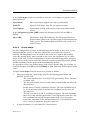
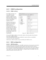
2.12.3 LED indicators Processing Unit
At the front of the Processing Unit there are four LED indicators. The LED to the left
indicates power and software status, the second to the left indicates MRU status, while
the LED to the right indicates network card status. The last LED has for the moment no
function and will always be turned off.
Figure 5 Front panel of Processing Unit
M300-62/rev.2
21
Seapath 320
The LED to the left indicates power and software status.
During start-up the indicator to the left
appears red.
When the software is up and running, the
indicator turns green.
The second LED to the left indicates MRU status.
The LED is red when there is no contact
with the MRU.
The LED is yellow when there is contact
with the MRU but PPS or data are
missing.
The LED is green when there is contact
with the MRU and PPS and data are OK.
The LED to the right indicates status of the four network cards.
The LED is red if there is an error on one
or more network cards.
The LED is green when all four network
cards are OK.
During normal operation, all LEDs should
be green as indicated to the right.
2.12.4 MRU to Processing Unit cable wiring
The MRU is connected to the Processing Unit with a cable which is terminated in the
MRU junction box in one end and with a 10 pin terminal for the Processing Unit in the
other end. The MRU is then powered from the Processing Unit.
The cable wiring is as follows:
22
Processing
Unit/MRU
Pin no.
Signal
Pair no.
Colour
MRU
junction box
Pin no.
MRU
connector
Pin no.
3
NC
Screen
chassis (x3
side)
10
24V_MRU
1 white
1 (x1 side)
R
1
GND
1 blue
2 (x1 side)
B
M300-62/rev.2
Installation Manual
Processing
Unit/MRU
Pin no.
Signal
Pair no.
Colour
MRU
junction box
Pin no.
MRU
connector
Pin no.
9
RX_B
2 white
3 (x1 side)
C
8
RX_A
2 blue
4 (x1 side)
T
7
TX_B
3 white
5 (x1 side)
S
6
TX_A
3 blue
6 (x1 side)
P
5
XIN/MRU_1PPS_P
4 white
23 (x1 side)
U
2
LGND
4 blue
24 (x1 side)
a
Table 12 MRU to Processing Unit cable wiring
The MRU is supplied with 24 V DC power from the MRU port on the Processing Unit.
Note
The shield around each pair in the cable has to be individually isolated in
the 10 pin terminal. The outer shield is connected to pin 8 (screen) in this
terminal, which is an open end (not connected to earth). In the MRU
junction box both the shield around each pair and the outer shield are
terminated in pin 1 (chassis) on the x3 side.
Note
It is important to insert a wire between pin 24 (LGND) and pin 27
(Shutoff) on the user side (x1) in the MRU junction box in order to
establish RS-422 communication between the MRU and the Processing
Unit. Otherwise there will be no communication between these two
components.
2.13
Interfaces HMI Unit
The rear panel of the HMI Unit contains communication interface ports for interfacing
to the Processing Unit. In addition, a USB and a LAN port are situated at the front
together with the power switch.
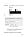
Connector
Type
Connected to
LAN
RJ-45
User configurable
USB 1
USB
User configurable
USB 2
USB
User configurable
Mouse
PS/2
Mouse
M300-62/rev.2
23
Seapath 320
Connector
Type
Connected to
Keyboard
PS/2
Keyboard
VGA
HD15 female
Monitor
100 - 240 V AC
Power
Input of 100 - 240 V AC
Table 13 Connectors at rear of HMI Unit
Connector
Type
Connected to
USB
USB
User configurable
Table 14 Connectors at front of HMI Unit
2.13.1 Pin layout
2.13.1.1 Ethernet connection
The HMI Unit has one LAN port at the rear. This port is mainly used to connect the
HMI Unit to the Processing Unit (normally LAN 2) via network. This LAN has 10/100
Mbps capacity.
To connect this LAN to a network, a straight-through twisted pair (TP) cable with RJ-45
connectors must be used. A straight-through cable is one where the pins of one
connector are connected to the same pins of the other connector. Below is the pin wiring
for the twisted pair (TP) cable:
Straight-through
Signal
Pin no.
Pin no.
Signal
TX+
1
1
TX+
TX-
2
2
TX-
RX+
3
3
RX+
RX-
6
6
RX-
Table 15 Pin layout for HMI Unit Ethernet ports
The pins 4, 5, 7 and 8 are not used.
24
M300-62/rev.2
Installation Manual
To connect the HMI Unit network, use twisted pair (TP) cable with RJ-45 connectors.
To comply with the IEC 60945 standard, shielded (screened) cable has to be used.
Recommended cable type is CAT-5e. Category 5e cable is an enhanced version of
Category 5 that adheres to more stringent standards. It is capable of transmitting data at
speeds of up to 1000 Mbps (1 Gigabit per second). The maximum length of the cable
that can be used is 100 metres (328 ft).
2.13.2 LED indicators HMI Unit
At the front of the HMI Unit there are four LED indicators. The LED to the left
indicates power and software status. The other LEDs have for the moment no function
and will always be turned off.
During start-up the indicator to the left
appears red.
When the software is up and running, the
indicator turns green.
Figure 6 Front view of HMI Unit
M300-62/rev.2
25
Seapath 320
26
M300-62/rev.2
Installation Manual
3 INSTALLATION
This chapter covers installation of the Seapath 320 system. The installation includes:
Location of the system parts (Processing Unit, HMI Unit, MRU, GNSS antennas)
Mounting of the Seapath cabinet
Mounting of the MRU bracket
Installation of the coax connectors
Mounting of the antenna bracket, GNSS antennas and cable
Connection of cables between Seapath and external equipment
System start
3.1
Logistics
Safety: General safety guidelines to be followed when working in mast and on deck.
Personnel qualifications: Trained electrical workers.
Minimum number of personnel: 2, especially when mounting the Antenna Bracket to
the Holder.
Ship location: The GNSS antennas have to be mounted such that blocking of the GNSS
signal is avoided. The MRU 5 unit is preferably mounted low in the ship or close to the
system to be compensated. The Processing Unit can be mounted on the bridge or in the
instrument room. The HMI Unit, the monitor is typically mounted on the bridge.
Special tools required: None.
3.2
Location of the system parts
The following sections contain instructions regarding mounting of the various system
parts.
M300-62/rev.2
27
Seapath 320
Figure 7 Location of system parts
3.2.1
GNSS antennas
For the GNSS antennas, consider the following:
The space above the antennas has to be free of obstructions of any kind. The antenna
should be protected from direct illumination of radar beams and other transmitting
antennas such as Inmarsat antennas. Seapath is more sensitive to blocking and
reflections (multipath) of GNSS signals than GNSS sensors which only utilise
pseudo-range data. This since Seapath also utilises carrier phase measurements for
heading determination, and both GNSS antennas need to see at least four common
satellites at the same time.
Caution
The GNSS antennas have to be mounted in such a way that
blocking of the GNSS signal I avoided.
In order to reduce problems due to multipath effects, the GNSS antennas have to be
mounted above the nearest deck at a height which is equal to the width of this deck
or higher.
The Antenna Bracket has to be mounted in such a way that torsion movement
relative to the ship's hull is kept at an absolute minimum.
28
M300-62/rev.2
Installation Manual
Note
If the Antenna Bracket supplied by Kongsberg Seatex is not used, it is
important that the antennas are rigidly mounted so that the distance
between the antennas does not change due to vibrations or accidental
dislocation.
The antenna baseline length is recommended in the range 2.5 to 4.0 metres, but 1 to 5
metres can be used. Maximum heading accuracy is achieved at 4.0 metres baseline.
The maximum length for each of the antenna coaxial cables is 100 metres for the
cable type normally delivered with the system (1/2" Superflex). If longer cables are
needed, a low noise signal amplifier (LNA) should be fitted.
3.2.2
MRU 5
For the MRU, consider the following:
The unit is designed for installation in an indoor environment and for operation
within the temperature range.
The unit is to be mounted close to the user equipment of which it is supposed to
measure the motion. This is to avoid errors in alignment with the user equipment and
to eliminate errors due to ship hull torsion.
If the system is not allocated to measure motion of a particular user equipment,
mount the MRU as close to the Navigation Reference Point (NRP) as possible. This
to ensure best roll and pitch measurements. If it is not possible to mount the MRU
close to NRP, try to mount it along the longitudinal axis of the ship and as close to
the NRP as possible. Avoid mounting the MRU high up or out to the side of the ship.
Be aware of:
Vibrations
Note
Direct mounting onto the main hull structure is preferable.
The worst mounting positions are thin walls that may come in resonance
with vibrations driven by machinery, propellers, pumps or motors. Avoid
mounting the MRU close to hydraulic pumps and valves where there are
high frequency vibrations.
Temperature changes For safe mounting of the MRU, place the unit in a location
where the temperature is low and where changes in temperature
are slow. A location directly on the hull far away from the heat
of the machinery, heaters and air conditioning systems is
preferable.
Corrosion problems Place the MRU in a location where no direct splashing seawater
is present.
M300-62/rev.2
29
Seapath 320
3.2.3
Processing Unit
When installing the Processing Unit, consider the following:
The unit is designed for indoor installation and should not be exposed to heavy
vibrations, transformers or similar.
The unit should be resiliently mounted in a 19-inch rack to be in accordance with the
environmental standard IEC60945/EN60945.
The unit has an internal fan and requires free airflow from the rear and out to the
sides. It is recommended that ventilation or air conditioning is provided in order to
keep the ambient operating temperature around +20 C. The best location is typically
in the instrument room or on the bridge mounted into a 19-inch rack with good
ventilation and resilient mounting.
It is recommended that the area around the unit is kept free from dust and static
electricity.
All connections to the unit are on the rear side and available space for cable
connections and service must be provided.
3.2.4
HMI Unit
When installing the HMI Unit, consider the following:
The unit is designed for indoor installation and should not be exposed to heavy
vibrations, transformers or similar.
The unit should be resiliently mounted in a 19-inch rack to be in accordance with the
environmental standard IEC60945/EN60945.
The unit has an internal fan and requires free airflow from the rear and out to the
sides. It is recommended that ventilation or air conditioning is provided in order to
keep the ambient operating temperature around +20 C. The best location is typically
on the bridge mounted into a 19-inch rack with good ventilation and resilient
mounting.
It is recommended that the area around the unit is kept free from dust and static
electricity.
All connections to the unit are on the rear side and available space for cable
connections and service must be provided.
3.2.5
Monitor
When installing the monitor, consider the following:
The unit is designed for installation in an indoor environment and for operation
within the temperature range. The best location is typically on a table in the
instrument room or on the bridge mounted close to the HMI Unit.
30
M300-62/rev.2
Installation Manual
The HMI Unit and the monitor should be mounted close to each other to reduce the
length of the VGA cable.
It is recommended that the area around the unit is kept free from dust and static
electricity.
3.3
Survey of sensors on vessels
All sensors need to be surveyed. The points to measure on the various sensors (MRU,
GNSS antenna, gyro), and the accuracy requirements, depend on the function of the
sensor.
If a sensor has a defined direction (fwd/stb/up), the direction in which it is mounted
must be determined.
All available sensors can be surveyed either in dock or alongside.
3.3.1
Vessel reference system
All vessels must have a defined Cartesian coordinate system to which all sensors must
be referenced. This system should be well described in both text and drawings to avoid
common misunderstandings.
Such a coordinate system can consist of a Y-axis (positive forwards) which is parallel to
the centre line of the vessel, an X-axis (positive to starboard) and a Z-axis (positive
upwards). All axes are mutually perpendicular.
The origin, where Y=0, X=0 and Z=0 (CRP, or Common Reference Point), is normally
defined to be at the AP (centre Rudder Stock, underside keel), which is also where the
design origin is commonly located in GA drawings.
The reference plane of this system must be well defined and described. This can be a
Best Fit Plane top main deck or a Best Fit Plane through the draught marks on the hull.
This is particularly important on a floating vessel, as it is not possible to project the
horizontal plane from land.
Note
If the CRP is to be located at the Centre of Gravity (COG), the load
conditions used when defining the COG must be known, as the actual
COG moves dynamically depending on load conditions of the vessel.
3.3.2
MRU
The following is to be surveyed:
Position (X,Y,Z) of sensor point (e.g. for an MRU 5 use centre top chassis)
Mounting angles:
Yaw (heading)
M300-62/rev.2
31
Seapath 320
Pitch
Roll
Pitch and Roll mounting angles should ideally be confirmed against MRU logs, for
instance during Gyro calibration.
3.3.3
GNSS antennas
The following is to be surveyed:
Position (X,Y,Z), centre of the antenna #1 disc (or otherwise defined sensor point).
Angular offset between the line from centre antenna #1 to centre antenna #2 and the
vessel centre line (CL).
Note
3.3.4
This offset should be confirmed against a Seapath GPS heading log,
typically during gyro calibration.
Gyro
If a gyro compass is interfaces to the Seapath system, the following is to be surveyed:
The offset between the gyro compass heading and the vessel centre line (CL).
Note
The heading offset to be surveyed to an accuracy better than 1°.
Static gyro calibration/verification (heading log) and DGNSS health check should be
done after all DGNSS and gyro systems are installed and fully operational. This can be
performed in dock or alongside.
Dynamic gyro calibration/verification and attitude control (heading, roll, pitch control)
must be performed at sea.
3.3.5
Survey accuracy
The Seapath 320 product must be surveyed to the following accuracy level. If not, the
performance of the product will be degraded.
Lever arm vector from CRP to GNSS antenna position (X, Y, Z): < 0.1 metre.
Lever arm vector from CRP to MRU (X, Y, Z): < 0.1 metre.
MRU 5 misalignment angles (Roll, Pitch, Yaw) with the vessel axes: < 0.1°.
32
M300-62/rev.2
Installation Manual
3.3.6
Cabinet mounting
3.3.6.1
Mounting Seapath with delivered cabinet
The cabinet should be securely mounted. Drilling plan for the resilient mountings is
included in the attached drawings.
Caution
The cabinet must be connected to a grounded outlet.
It is recommended that the cables attached to the rear of the unit should be long enough
to accommodate all service from the front.
The cabinet must be mounted in such a way that the minimum cable bends (on the rear
side) are not exceeded. For the antenna cables it may be necessary to use the short
transition RG-213 or RG-214 cable in order to route the cables properly into the cabinet.
3.3.6.2
Mounting Seapath without delivered cabinet
A system delivered without a cabinet shall be mounted on attachment rails in a standard
19-inch rack. Minimum depth of the rack is 500 mm. It is recommended that the rack is
resiliently mounted.
It is recommended that the rack has air inlet on top and bottom or ventilation splits on
the sides. The Processing and HMI units have ventilation on the sides. Forced
ventilation may be required if the cabinet contains several electronic modules.
All cables connected to the unit must be screened. Make sure that the minimum antenna
cable bends are not exceeded.
Note
The recommended keyboard cable length is 3.3 m (10 feet) maximum
without degradation. If longer keyboard cable is needed, please use
keyboard extender.
3.4
Installation procedures
3.4.1
Mechanical installation
The mechanical installation consists of:
Making a holder for the Antenna Bracket and having it fastened in a suitable location
in a mast.
Mounting the Antenna Bracket with the GNSS antennas on a holder in the mast.
Mounting the MRU bracket and the MRU near the user equipment for which attitude
data is wanted, or close to the selected Navigation Reference point.
M300-62/rev.2
33
Seapath 320
Mounting of the Processing Unit in a rack in the instrument room or bridge.
Mounting of the HMI Unit in a rack in the instrument room or bridge.
Mounting the monitor close to the HMI Unit.
The installation procedure described below assumes that the Antenna Bracket delivered
by Kongsberg Seatex is used and that a holder for this Antenna Bracket is prepared in
accordance with the antenna holder drawing in chapter 5.
3.4.1.1
GNSS antennas
The mechanical installation of the various parts is performed in the following steps:
1
First the user has to make a holder for the Antenna Bracket (the holder is not part
of the Seapath delivery) and have it properly fastened to the mast in the preferred
orientation (horizontal or vertical). When the Antenna Bracket is mounted
vertically, the drawings in Figure 8, Figure 9 and Figure 10 are not correct.
Figure 8 Dimensional drawing for antenna holder
2
34
Bring the Antenna Bracket, the two GNSS antennas and the antenna cables as
close as possible to the location of the antenna holder. While both the GNSS
antennas and the Antenna Bracket are down on deck, mount the GNSS antennas
on the Bracket with both antennas oriented in the same direction. Depending on
antenna type, labelling on the antenna housing (arrow or text) or connector
location is used to determine direction. Figure 9 shows the antennas oriented with
connectors pointing in the same direction. The antennas are not marked, and are
interchangeable but called no. 1 or 2 for reference. The normal orientation of the
Antenna Bracket is along ship with antenna no. 1 aft. It can, however, be mounted
in any orientation, provided it is approximately horizontal.
M300-62/rev.2
Installation Manual
Note
Both GNSS antennas have to be mounted on the Bracket oriented in the
same direction, otherwise the system will have degraded heading
performance.
Figure 9 Top view of Antenna Bracket
3
The screws for mounting the GNSS antennas to the Bracket must be secured with
washers.
4
Connect the antenna cables to both GNSS antennas. The connection between the
antenna and the antenna cable should be sealed against water penetration,
preferably by using waterproof self-vulcanising tape. The GNSS antenna cables
are then strapped inside the Antenna Bracket as shown in Figure 11.
5
Lift the Antenna Bracket in the preferred direction on the holder.
Figure 10 Different components for mounting of Antenna Bracket
6
Ensure that the delivered insulation plate is used between the Antenna Bracket
and the holder, and that the four bushings are placed in the mounting holes before
the screws are entered. The nuts should be secured with washers or by utilising
self-locking nuts.
M300-62/rev.2
35
Seapath 320
Figure 11 Side view of GNSS antenna installation
3.4.1.2
MRU, Processing and HMI Unit
The mechanical installation consists of:
Mounting the MRU bracket and the MRU near the user equipment for which attitude
data is wanted, or close to the selected Navigation Reference point.
Mounting of the Processing Unit in a rack in the instrument room or bridge.
Mounting of the HMI Unit in a rack in the instrument room or bridge.
The mechanical installation of the various parts is performed in the following steps:
1
36
When the best mounting location for the MRU has been identified, place the
MRU mounting bracket in the preferred orientation and make screw holes in the
foundation. If the orientation of the bracket can be freely selected, mount the
bracket on the longitudinal or transversal bulkheads of the ship with the opening
pointing downward, as shown in Figure 12. This will ensure easy and accurate
orientation of the MRU according to the longitudinal axis. Reserve sufficient
space below the bracket to allow insertion of the MRU from below.
M300-62/rev.2
Installation Manual
Figure 12 Recommended orientation of the MRU mounting bracket
2
Mount the MRU bracket on the wall, preferably with the opening pointing down,
as shown in Figure 13. Mark and drill a M6 hole for the top screw (1) and enter
the screw without tightening it completely. Align the bracket vertically using its
own weight or by aligning it in relation to the wall. Drill two holes for the lower
screws (2) and insert and securely tighten all three screws, using washers or selflocking nuts.
Figure 13 Wall mounting of bracket with MRU connector pointing down
M300-62/rev.2
37
Seapath 320
3
Note
4
Insert the MRU into the bracket. In order to achieve the orientation as shown in
Figure 12, the MRU must be rotated in the bracket. Apply Loctite 242 glue or
equivalent on the four MRU screws (3).
The MRU R+ arrow must always point in the bow direction unless the
default mounting orientation of the unit is modified in the MRU
configuration
Apply the sticker (4) onto the bracket according to the actual mounting direction
of the MRU, as shown in Figure 14. In this way, the actual mounting direction is
identified in case the unit is to be exchanged or removed temporarily.
Figure 14 Sticker (4) shall indicate actual MRU mounting orientation within bracket
Note
5
38
If the MRU is mounted correctly in the bracket, the +R arrow on the top of
the MRU will point in the bow direction of the ship and the same direction
as the R-axis of the sticker. If uncertain whether the MRU R-axis is
pointing in the bow direction, look under the MRU and check that the +R
arrow label is pointing in the bow direction. Precise MRU orientation is
important to ensure that high quality and accurate measurements are
available to the host system
Mount the junction box on the wall in a suitable location within the length of the
3-metre MRU-E-CS1 cable, as shown in Figure 15 MRU junction box mounting
M300-62/rev.2
Installation Manual
6
The screws for mounting the junction box should be secured with washers or selflocking nuts.
Figure 15 MRU junction box mounting
7
Mount the Processing Unit in a standard 19-inch rack in a preferred location. The
Processing Unit has to be fastened both in front and rear of the rack. Minimum 10
cm free space is needed behind the module for connection of cables.
8
Mount the HMI Unit in a standard 19-inch rack in a preferred location. The HMI
Unit has to be fastened both in front and rear of the rack. Minimum 10 cm free
space is needed behind the module for connection of cables.
3.4.2
Electrical installation
The electrical installation consists of:
Connecting two cables between the GNSS antennas and the Processing Unit.
Connecting a cable between the MRU junction box and the Processing Unit.
Connecting an Ethernet cable between the Processing and the HMI Unit.
Connecting the monitor, the keyboard and the PC mouse to the HMI Unit.
Connecting cables with output data between the Processing Unit and external
equipment (optional).
Supplying 110/240 V AC power to the Processing Unit, the HMI Unit and the
monitor.
M300-62/rev.2
39
Seapath 320
3.4.2.1
Caution
1
Installation procedure
Attach the antenna cables to the GNSS antennas on the Bracket
before attaching the antenna cables to the Processing Unit. If
the antenna cables are attached to the Processing Unit, do not
attach the antenna cables to the GNSS antennas with the
Processing Unit powered on. If the antenna cables are shortcircuited with power on, the GNSS receivers within the
Processing Unit will be damaged.
Connect the two GNSS antenna cables to the connector 1 (for GNSS antenna 1)
and connector 2 (for GNSS antenna 2) at the rear of the Processing Unit.
See APPENDIX B on how to install the coax connector on the Superflex antenna
cable.
See APPENDIX C for more details on how to install the GNSS antennas.
2
Note
Wrap outdoor cable connections with waterproof self-vulcanising tape. An
alternative way of waterproofing is to use heat shrink hose with glue. The hose
should cover the whole connector and part of the cable.
The GNSS antenna cables must be as straight as possible. Do not crush or
crimp the cable with tie-downs as this will affect the electrical properties
of the cables.
3
Enter the cable from the MRU port at the rear of the Processing Unit through one
of the free nipples on the junction box. Ensure that the cable shield is in contact
with the nipple for grounding before the cable is fastened to the box. Use the
required number of clips to fasten the cable to the wall.
4
Insert each of the MRU to Processing Unit cable wires into the correct terminal on
the user side (x1) and all cable shields to pin 1 (chassis) on the auxiliary contact
side (x3) within the box. Ensure that the shield around each pair in the cable is
individually isolated on the 10 pin terminal. The outer shield is connected to pin 3
(screen) on this terminal, which is an open end (not connected to earth).
5
Insert an isolated wire between pin 24 (LGND) and pin 27 (Shutoff) on the user
side (x1) in the junction box. By connecting these two pins, the communication
with the MRU will switch from RS-232 to RS-422.
Note
40
It is important to insert a wire between pin 24 (LGND) and pin 27
(Shutoff) on the user side (x1) in the MRU junction box in order to
M300-62/rev.2
Installation Manual
establish RS-422 communication between the MRU and the Processing
Unit. Otherwise there will be no communication between these two
components.
Note
The junction box housing is grounded to earth through the screws for
mounting the box to the wall or floor. Please note that if the foundation on
which the junction box is mounted, is NOT connected to earth, one of the
junction box mounting screws has to be connected to earth by connecting a
wire from the screw to an object that is connected to earth.
|-----------------------------User side x1-----------------------------|
6
pin
signal
description
pin
signal
description
1
PWRIN+
power +
23
XIN
to MRU
2
PWRIN-
power gnd
24
LGND gnd ref.aux.+dig
3
TX+
from MRU
27
SHUTOFF
4
TX-
-"-
5
RX+
to MRU
6
RX-
-"-
of MRU
Connect the cables for output data from Seapath to external equipment to the Com
ports 1 and 2 or the terminals Com9 to Com14, analog output signals or the
Ethernet connection.
Note
Cable with shield has to be used in order to fulfil the Seapath power and
EMC requirements.
7
Connect the 110/230 V AC ship's power supply to the power connector at the rear
of the Processing Unit.
8
Connect the 110/230 V AC ship's power supply to the power connector at the rear
of the HMI Unit.
9
Connect the cable from the monitor, PC mouse and the keyboard to the
corresponding connectors at the rear of the HMI Unit.
10
Connect the monitor for the HMI Unit to 110/230V AC ship power.
M300-62/rev.2
41
Seapath 320
11
If available, connect the signal cables with DGNSS correction and external gyro
compass to free terminals at the rear of the Processing Unit.
12
Connect an Ethernet cable from the LAN port on the rear of the Processing Unit
and the HMI Unit to the network onboard the vessel or a direct connection
between the two units.
13
When all cables are connected, power on the Processing and HMI Units, the four
LED indicators located on the front panel of the Processing Unit should then start
to shine red. The LED1 light diode in the MRU junction box should then shine
green indicating that the MRU receives power. A yellow light in LED2 indicates
that digital data are sent from the MRU on TX+.
14
If the software starts on both the Processing and the HMI Unit, the installation is
now completed and the setup of the configuration parameters can continue.
3.4.3
Setup of configuration parameters
Setup consists of:
Entering lever arm vectors and mounting angles for the MRU and the GNSS
antennas in the NavEngine configuration of the operator software.
Entering input and output data interface in the NavEngine configuration of the
operator software.
The setup parameters are entered into the operator software on the HMI Unit.
See chapter 4.1. for a description of the operator software.
3.4.3.1
Lever arm vector determinations
The following lever arm vectors have to be determined and input to the operator
software:
The vector from the selected AP to the GNSS antenna no. 1.
The vector from the selected AP to the MRU location.
The vectors from the selected AP to each of the monitoring points (maximum eight
MPs).
All these vectors have to be measured or calculated based upon drawings or previously
measured points. These vectors are to be measured within an accuracy described in
chapter 3.3.5. Positive vector orientation for these parameters is X - positive forwards,
Y - positive towards starboard, Z - positive downwards with the AP (Aft Perpendicular)
as the origin.
42
M300-62/rev.2
Installation Manual
Figure 16 Offset vectors between the different components
3.4.3.2
Setup procedure
1
Power on both the Processing and HMI Units and follow the configuration
procedure for the operator software described in chapter 4.1.
2
Edit the Seapath parameters and Apply in order to download the entered
configuration parameters to the Processing Unit. For more description of each of
the configuration parameter selections, see chapter 4.4.
3.4.4
Calibration
The system has to be calibrated on board the vessel after installation. A typical
calibration consists of:
Calibrating the direction of GNSS antennas against an external reference. Type of
reference must be decided according to the required accuracy.
Calibrating the MRU axes measured by the MRU against an external reference.
Decision on whether MRU calibration is needed and type of reference, is based on
the type of system to which the Seapath is interfaced and the accuracy required.
3.4.4.1
Calibration of the GNSS antenna installation
For the GNSS antenna installation the following calibration parameters have to be
determined:
Baseline Length. The baseline length between the two antennas is measured in
metres. The length can be selected in the range 0.2 to 6.0 metres, but the
recommended antenna baseline length range is 2.5 to 4.0 meters.
M300-62/rev.2
43
Seapath 320
Heading Offset. The direction of the GNSS antennas relative to the vessel's
longitudinal axis is measured in degrees.
Height Difference. The height difference between the two antennas according to the
vessel horizontal plane (the height to antenna #1 minus the height to antenna #2,
compensated for vessel roll and pitch) is measured in metres. This is an absolute
value (always positive).
It is of crucial importance to calibrate the heading offset correctly. During this
calibration, several accurate reference measurements of the vessel heading must be
read/logged simultaneously with the heading output from the Seapath. The data logging
should continue for at least two hours under calm conditions alongside a quay. The best
results are achieved if continuous logging of both the reference system and the Seapath
measurements can be performed during the calibration period. If simultaneous logging
of the two systems is not possible, one reading from both systems should be done at
least every 30 seconds for a minimum of two full hours.
The long calibration time is necessary in order to cancel out errors in the Seapath
measurements caused by multipath effects, which may be particularly pronounced in the
static conditions of a harbour area.
Before calibration, measure the baseline length between the GNSS antennas to within a
tolerance of one centimetre or better. If the standard antenna bracket is used, the
baseline is 2.5 metres. Enter the measured baseline length into the Processing Unit by
using the operator software.
The observations from each of the two different systems are then averaged and the
offset between the two systems (reference minus Seapath reading) is the Seapath
heading offset. If heading offset was not entered as zero in the operator software on
beforehand, the calibration value should be added to the existing offset value.
The baseline length and height difference should be determined within an accuracy of
10 centimetres in height difference and 1 mm in baseline length. These values should be
entered into the Seapath through the operator software configuration dialog under
NavEngine configuration in the System menu. By using the calibration wizard in the
operator software the baseline length and height difference are calculated automatically.
Note
Before starting the calibration wizard, the MRU mounting angles have to
be correct and used by the Seapath (applied before entering the
calibration wizard). Else the calculation of the height difference will be
incorrect, unless the vessel has zero roll and pitch. Incorrect height
difference will degrade the heading accuracy.
Example:
If the heading measured by the reference system is found to be 32.1 degrees and the
Seapath heading after the calibration has been determined to be 15.3 degrees, the
Seapath heading offset to be input in operator software is the value 16.8 (32.1 - 15.3).
44
M300-62/rev.2
Installation Manual
3.4.4.2
Typical calibration procedure
This is an example on how to perform a GNSS antenna calibration. Proceed as follows:
1
Before entering the calibration wizard, ensure that the correct MRU mounting
angles are used by the Seapath (press Apply on MRU mounting angle changes
before entering the calibration wizard). Else the calculation of the height
difference in the calibration wizard will be incorrect, unless the vessel has zero
roll and pitch. Incorrect height difference will degrade the heading accuracy.
2
Select the System menu and NavEngine to enter the NavEngine configuration
dialog. Select Sensors\GNSS\Geometry as shown in the figure below.
M300-62/rev.2
45
Seapath 320
3
In the Antenna configuration window, input the Baseline length 2.5 metres if the
standard Antenna Bracket is used, otherwise this length has to be measured
manually with 1 cm accuracy and this value entered. For the Antenna orientation
input an approximate value or input zero if you are uncertain. For the Height
difference input an approximate value. Then click on the Calibration wizard
button to prepare the calibration.
4
In the Antenna calibration wizard – Page 1 Input Parameters, Step 1 check that the
baseline length has been entered correctly.
Figure 17 Page 1 of GNSS antenna calibration
5
In Step 2 input 120 minutes (two hours) as the calibration period and the logging
interval as 10 seconds. Log the calibration data to the file "Seapath.cal" on a
preferred folder on the PC.
6
Before pressing Next and start logging of Seapath GNSS, it is recommended to
start recording data of the vessel reference heading on another PC or by manual
readings. When logging of the reference heading has started, click Next in order
to proceed to page 2 Processing.
7
The progress of the calibration process is then shown on the screen with a
graphical presentation of the measured data for the Seapath heading, the gyro
compass (if connected), the antenna baseline length and the height difference.
46
M300-62/rev.2
Installation Manual
Figure 18 Page 2 of antenna calibration wizard
8
Click Next to proceed to page 3 Data edit for information about the calibration
result.
Figure 19 Page 3 of antenna calibration wizard
M300-62/rev.2
47
Seapath 320
9
Inspect the logged calibration data (in the file "Seapath.cal") for any wild points
by selecting the command Show graph. Correct the wild points found or delete
the whole line(s) and perform a recalculation of the calibration data.
10
When the Seapath calibration result has been found acceptable, click Next to
proceed to page 4. Input the mean value for the vessel heading reference, in this
example logged on a separate PC and found to be 160.00 degrees, and click on
Compute in order to calculate the heading offset.
Figure 20 Page 4 of antenna calibration wizard
11
Click Finish to accept the result and exit the antenna calibration wizard.
3.4.4.3
Calibration of MRU axis
After the mechanical installation is completed, the MRU R, P and Y axes must be
aligned to the corresponding vessel axes or the axes of the system to be compensated.
To achieve the MRU's specified roll and pitch accuracy, any misalignment of the MRU
axes with the vessel axes must be precisely calculated and accounted for. The MRU
axes, and particularly the yaw axis, must be aligned with the vessel axes with an
accuracy better than 0.5 degrees to ensure that the MRU functions are according to
specifications. For multibeam echo sounder applications an accuracy better than 0.1
degrees is required to ensure satisfactory performance.
48
M300-62/rev.2
Installation Manual
A typical alignment process
consists of aligning the MRU
axes to an external reference.
Type of reference must be
determined according to the
required accuracy.
The reference for roll and
pitch alignment must be
carefully selected depending
on the intended application. It
may be the hull, a sensor such
as a multibeam echo sounder
or a USBL acoustic system.
Some sensors have internal
alignment routines, and
accurate alignment of the
MRU is not required. The
MRU mounting wizard is
described later in this manual.
This includes an automatic
procedure for obtaining the
roll and pitch mounting
angles.
Figure 21 Alignment of MRU yaw axis to vessel
longitudinal axis
An accurate alignment of the MRU +R arrow towards the vessel's longitudinal axis
(yaw orientation) is of special importance. If not properly aligned, the performance of
the roll and pitch measurements from the MRU will be degraded. Figure 22 illustrates
that a misalignment of 1 degree of the MRU in yaw will result in a roll error of ±0.09
degrees if the vessel is pitching ±5 degrees. To calculate the misalignment of the MRU
axis to an accuracy of 0.5 degrees or better is not an easy task and requires use of an
accurate external reference.
M300-62/rev.2
49
Seapath 320
Figure 22 Value of roll error as a function of vessel pitch angle, displayed at 0.5°, 1°
and 1.5° MRU yaw misalignment
50
M300-62/rev.2
Installation Manual
4 CONFIGURATION
Seapath has a graphical user interface which includes configuration, data presentation
and sensor status. This chapter describes the Seapath configuration management system.
4.1
Starting the system
After installing the equipment according to the procedures, the system can be started.
Press the power switch on the front of the Processing and HMI Units to start the
systems.
The system will start automatically after power on. Normally, the unit will output
signals on the serial lines without any involvement from the user.
4.2
System configuration
4.2.1
System modes
The product has three system modes, indicated in the System mode field of the Top
bar:
Operation mode
This is the default
mode. In this mode it
is not possible to
launch any external
applications,
diagnostic tools or
reconfigure the
system.
Configuration mode In this mode it is
possible to change
settings related to the
connected sensors,
applications and
system-wide settings.
Engineering mode
Figure 23 Change system mode menu
This mode is primarily intended for field engineers during initial
installation, fault diagnostics and system-wide reconfiguration.
A password is required to switch from Operation to Engineering or Configuration mode.
The password is "stx", and it is not possible to change. The system will return to
Operation mode after 3 minutes of user inactivity.
M300-62/rev.2
51
Seapath 320
4.3
NavEngine configuration
From the System menu,
configuration of NavEngine is
available. Two modes of
configuration are available,
Standard and Advanced. The
Standard configuration is
available when logged into
Configuration mode, while the
Advanced configuration is
available in Engineering mode.
Figure 24 NavEngine configuration
4.4
Standard configuration
When Standard configuration is selected from the System menu, the NavEngine
Configuration view is displayed.
Figure 25 NavEngine Configuration view
At the top of the NavEngine Configuration view there are three buttons to handle the
configuration parameters.
52
M300-62/rev.2
Installation Manual
Apply
To save the parameter
settings, the Apply button
must be pressed.
Revert
The Revert button contains
the last applied
configuration parameters.
History
A new configuration file is
stored each time the Apply
button is pressed. From the
History button, the saved
files are available. The files
are named with the date and
time they were saved. The
ten last files are displayed in
the list. Via the
Browse…button at the
bottom of the list it is
possible to find all saved
files.
Figure 26 History button
The following parameters can be set in the Standard
configuration:
- Vessel geometry and description
- Sensor data, including:
- GNSS geometry and processing
- DGNSS and SBAS
- MRU geometry and heave config
- Monitoring points geometry
- Communication interface, including:
- Input/Output
- Data pool
Figure 27 Configuration
manager
M300-62/rev.2
53
Seapath 320
4.4.1
Vessel configuration
In the Vessel configuration the following can be input:
Geometry
For later configuration of sensor and monitoring point locations
on the vessel it is an advantage that the background vessel
(vessel shape) is as equal as possible to the vessel on which the
system is installed. The background vessel is scaled on the
screen to be equal to the installed vessel. To scale the vessel
shape on the screen to the actual vessel, its dimensions have to
be input.
Description
Vessel data for the specific installation. This information is
helpful to identify the correct configuration file at a later stage.
4.4.1.1
Vessel geometry
The Vessel Geometry view defines the vessel dimensions.
Figure 28 Vessel geometry view
In the Vessel dimension section it is possible to set the following parameters:
LOA
The overall length of the vessel, i.e. from stern to bow [m].
Overall width
The overall width of the vessel [m].
Overall height
The distance from the highest point of the vessel to the keel [m].
Stern to AP
The distance from the aft point of the ship to its AP [m].
54
M300-62/rev.2
Installation Manual
In the Vessel shape section it is possible to select the vessel shape or to get the vessel
shape from a file.
Vessel shape
The vessel shapes supported are ship, rig and jackup.
From file
Input of vessel shape from file, see separate section.
Vessel opacity
A percentage scaling of the opacity of the vessel shape on the
screen.
In the Navigation ref. point (NRP) section, the distance between AP and NRP is
defined.
AP to NRP
4.4.1.2
The distance from AP to NRP [m]. The Navigation Reference
Point location (NRP) is the reference point for all measurements
in the system. The recommended used NRP is the vessel CG or
rotation centre.
Vessel shape
For later configuration of sensor and monitoring point locations on the vessel, it is an
advantage that the vessel is of the same shape as the vessel where the system is
installed. The background vessel is scaled on the screen to be equal to the installed
vessel. By moving the PC mouse around on the vessel, the coordinates (x,y,z) will be
shown in full scale. For later configuration of sensors and monitoring points, just place
the PC mouse on the screen on the spot where the sensor or monitoring point is wanted
and the coordinates for this point are then automatically defined.
It is possible to select a pre-defined shape of the vessel, which is ship, rig or jackup, or
to define the shape from File as a User Bitmap or User Text with 2D description of the
vessel.
To input Vessel shape from file as user text, proceed as follows:
1
When generating the vessel image from file, the following data format and
structure is to be used:
- The vessel data have to be in an ASCII file generated by Excel, Notepad
or similar tools.
- The file head includes LOA, Overall width, Overall height and Aft to AP
data in metres.
- Profile data in X and Z coordinates in metres. The first coordinate has to
be for AP and start with 0.00 and the last coordinate has also to be AP
end with 0.00.
- The top view data in X and Y coordinates in metres. The first coordinate
has to be for the aftermost point on the vessel and on the centre line. The
last coordinate has to be the foremost point on the vessel and on the
centre line. Only data for the starboard side of the vessel should be input
since a vessel is symmetric along the centre line.
2
A typical example of a vessel data file is shown below:
M300-62/rev.2
55
Seapath 320
Figure 29 Example GA drawing of multi-purpose vessel
Figure 30 Example of vessel shape in user text file
56
M300-62/rev.2
Installation Manual
Figure 31 Example vessel shown in Vessel Geometry view
4.4.1.3
Vessel description
The Vessel Description view contains mostly textual information regarding the vessel.
Figure 32 Vessel Description view
Vessel name
The name of the vessel.
Vessel owner
The name of the vessel owner.
Country of origin
The name of the vessel's country of origin.
MMSI
The MMSI assigned to the vessel.
IMO Number
The IMO ID assigned to the vessel.
M300-62/rev.2
57
Seapath 320
4.4.2
GNSS configuration
4.4.2.1
GNSS Geometry
The lever arm vector from the AP to GNSS antenna no. 1 has to be measured or
calculated based upon drawings or previously measured points, and entered into the
software. The antenna cable connected to GNSS1 at the back of the Processing Unit will
be GNSS antenna no. 1 in the installation. Proceed as follows:
Antenna location. Set the Antenna location coordinates for the GNSS antenna
which is defined to be antenna no. 1, normally the antenna closest to the aft of the
vessel. Check that the antenna has been located on the expected spot in the vessel
shape. If not, check the signs and the co-ordinates input for GNSS antenna no. 1, the
vessel dimension and the entered location of AP.
Antenna configuration. In the Antenna configuration section, input the antenna
type (Novatel NOV600, NOV702 or NOV702GG or GENERIC. NONE means no
antenna dome or choke ring included), baseline length 2.5 metres if the standard
Antenna Bracket is used, otherwise this length has to be measured manually and this
value entered. For the heading offset and height difference input zero. Then click on
the Calibration wizard button to prepare the calibration. The Heading Offset and
Height Difference is automatically updated trough the Calibration wizard process.
Check that the orientation of the antennas in the vessel shape correspond with the
actual orientation in the mast. See the chapter Calibration for description on how to
use the Calibration wizard.
Note
58
Correct selection of antenna type is only important when raw GNSS data
are output from the Seapath for post-processing of the position accuracy.
The selection GENERIC as antanna type is used for all single-frequency
antennas (L1) and for Seapath installations that shall not use RTCM
output for post-processing. If other antennas than those listed are used,
check the following link to find the correct antenna type;
ftp://igscb.jpl.nasa.gov/igscb/station/general/rcvr_ant.tab. Other antenna
types than those listed are input in the Seapath configuration by using the
Advanced option in NavEngine configuration on the System menu.
M300-62/rev.2
Installation Manual
Figure 33 GNSS sensor geometry configuration view
4.4.2.2
GNSS Processing
For operations with weak satellite geometry the position output can be made more
accurate by using height aiding and low elevation mask. For normal operations the
Height Aiding mode is set to Off but Filter is also recommended used. The elevation
mask is set to 10 degrees as the default value and must not be changed by other than
experts. For the Seapath 330 models the search mode for the RTK solution has three
selections: Safe, Normal and Fast. The default RTK search mode is Normal. In order to
change the default GNSS Processing settings, proceed as follows:
Set the Seapath in Height Aiding mode by pulling down the Aid Mode drop-down
list and change the selection from Off, which is the default setting, to Filter. The
Aided Height is the height of NRP above sea level. This height should be set when
Filter is selected since the filter will start with the entered height value as the initial
value.
The SV masking value can be changed from the default value 10 by entering an
Elevation mask value between 7 and 20 degrees. This value must not be changed by
other than experts from the default value 10.
Click the checkbox Enable range rate corrections to use the DGNSS corrections in
the GNSS velocity calculations. The default setting is enabled on use of range rate
corrections. Disabling range rate corrections will reduce velocity and attitude noise
when receiving DGNSS corrections from a reference station with a noisy range rate.
For the Seapath 330 models the search mode for the RTK solution should be changed
from the default mode Normal to Safe or Fast by pulling down the RTK search mode
M300-62/rev.2
59
Seapath 320
drop-down list. The Safe mode is recommended used under difficult conditions with
much multipath or ionospheric activity and for long baselines. The Fast mode is used
when a fast RTK solution is required. However, in this mode the probability for an
incorrect solution from the system increases.
Figure 34 GNSS Processing settings view
4.4.2.3
GNSS Attitude Processing
In this dialogue the maximum values to be used for attitude processing can be changed.
However, these parameters are only to be changed if the vessel has an unusual
characteristic.
Figure 35 GNSS Attitude Processing view
60
M300-62/rev.2
Installation Manual
4.4.3
DGNSS configuration
4.4.3.1
SBAS tracking
In the SBAS tracking view
it is possible to set up
Automatic or Manual
tracking of SBAS satellites.
When Automatic tracking is
selected, the GNSS receiver
chooses which SBAS
satellites to track.
In Manual mode the user
must set up which SBAS
satellites to use. If two
SBAS satellites are
selected, the system will
automatically select and use
data from the best satellite.
If only one SBAS satellite
is selected, only correction
data from this satellite will
be used in the
computations.
Figure 36 SBAS tracking view
If no specific SBAS satellite is selected, the system will select and use data from the
best of the available satellites.
If the selected SBAS satellite is not available, the system will not use the SBAS
correction data in the computations.
Maximum two SBAS satellites may be tracked by the GNSS receiver.
4.4.4
MRU configuration
4.4.4.1
MRU Geometry
The lever arm vector from the AP to the MRU location has to be measured or calculated
based upon drawings or previously measured points, and entered into the software.
Look at the sketch of the MRU geometry on the screen in order to enter correct signs on
the co-ordinates. Check also that the MRU has been located on the expected spot in the
vessel shape. If not, check the signs and the co-ordinates input for the MRU, the vessel
dimension and the entered location of AP.
M300-62/rev.2
61
Seapath 320
The MRU mounting angles can either be input manually or determined by use of the
Mounting Wizard. To use the MRU Mounting Wizard, see separate section in this
manual.
Figure 37 MRU geometry view
MRU location
Enter the position of the MRU in X, Y, Z coordinated from
AP. The MRU location has to be measured or calculated
based upon drawings or previously measured points.
MRU mounting angles The mounting angles of the MRU in roll, pitch and yaw have
to be input to the MRU. The MRU mounting wizard can be
used to determine these mounting angles.
4.4.4.2
MRU mounting wizard
To use the MRU Mounting Wizard proceed as follows:
1
Press the Mounting wizard button in the MRU Geometry view.
2
Select Manual mode in Step 1 and click Next, see Figure 38.
62
M300-62/rev.2
Installation Manual
Figure 38 Step 1 of MRU axis orientation
3
Click the << or >> buttons in the lower left part of Figure 39 to turn the MRU unit
around in 90-degree steps, axis by axis. Click until correct mounting orientation of
the MRU has been found. The right part of this dialogue is automatically updated
with the actual main rotation of the MRU. Click Next to proceed to Step 3.
Figure 39 Step 2 of Manual input of mounting angles
M300-62/rev.2
63
Seapath 320
4
At the top right of Figure 40 the main rotation angles of the MRU are displayed.
Enter the offset angles for Roll, Pitch and Yaw from the main rotation angles.
Press the Help button to get more help on the sign of the offset angles. A positive
offset angle rotation is:
- Positive roll offset means starboard (right) side facing downward, or a
clockwise rotation about the x-axis.
- Positive pitch offset means bow up, or a clockwise rotation about the yaxis.
- Positive yaw offset (heading, azimuth) means a turn to starboard (right),
or a clockwise rotation about the z-axis.
Figure 40 Step 3 of Manual input of MRU mounting angles
5
Note
64
Press Finish to finish the manual setting of the MRU axis.
The new MRU mounting angles are only valid in this system after pressing
the Apply button.
M300-62/rev.2
Installation Manual
4.4.4.3
Heave configuration
When using real-time heave measurements, it is important to tune the heave parameters
(heave period and damping) to the vessel size and the motion characteristics for the
actual weather conditions. The default settings for filter mode heave period and
damping, have to be tuned for the actual vessel and weather conditions in order to
achieve optimum heave performance. Therefore, before a survey and/or during
operation check the heave performance of the Seapath and tune the heave parameters
until the best heave performance is achieved. An alternative is to select Automatic and
let Seapath automatically choose the best settings. The following should be considered
when selecting the different heave filter modes and parameters:
Filter mode:
Automatic. To be selected when the vessel is operating in various sea states or when
the average heave period is unknown.
General purpose. Is selected when an optimal heave amplitude is to be measured
and the heave phase is of no importance. This mode is typically selected when the
Seapath is to be used for measuring the heave height and period on oceanographic
buoys.
Hydrographic survey. To be selected when the heave phase and amplitude have to
be output correct in real time. This mode is typically selected when the heave output
signal from the Seapath is to be used for heave compensation of echo sounders and
offshore crane systems.
Period:
An expected average heave period has to be set to the heave filter. This period can be
determined by measuring the time between two wave-tops by using a watch.
The settling time for the heave measurements from power-on or after a turn will be
about 10 times the selected period, To. By selecting an unnecessary long heave
period, the settling time will be slower than it has to. For vessels performing surveys
with frequent turns, the period should be set as low as possible to minimise the heave
settling time after turns.
Damping:
The heave damping factor is usually set to 0.7. Only for special occasions should this
parameter be changed. In operations with heave periods of more than 25 seconds, the
damping factor should be reduced to 0.6 in order to achieve correct phase
measurements. In operations with heave periods of less than 2 seconds, the damping
factor should be increased to 0.8.
For more details on selection of heave filter mode and parameters, see the User
Manual.
In order to select the heave configuration proceed as follows:
M300-62/rev.2
65
Seapath 320
Enter the settings for heave filter in the MRU Heave config dialogue. The pull-down
Option menu has the following options; Integrated, Automatic, Hydrographic survey
or General purpose. In Integrated, Hydrographic survey and General purpose mode,
the filter parameter for Period can be set to a value between 1 and 25 seconds, and
the Damping value between 0.2 and 1.
Figure 41 Heave filter view
Click on the checkbox Roll/Pitch dependent in the Heave mean level section to
make the heave measurement dependent on the roll and pitch measurements. Then
the heave position in the monitoring points (MP) now longer has zero mean level,
instead its value depends on the vessel tilt at any time. This option is useful
especially in applications where the distance between the MP and the sea level is to
be determined, like in echo sounder installations with depth changes due to changes
in vessel trim and list. If this mode is not selected, the heave will always have zero
mean level.
4.4.5
Monitoring points
Enter the Monitoring Point configuration dialogue to configure monitoring points for
output of data. Up to 8 monitoring points may be defined. As the monitoring points are
inserted, they are displayed graphically. The monitoring points are given relative to the
AP.
Check that the monitoring points have been located on the expected points in the vessel
shape. If not, check the signs and the co-ordinates input for each monitoring point, the
vessel dimensions and the entered location of AP.
66
M300-62/rev.2
Installation Manual
Figure 42 Monitoring points view
To add a monitoring point, select the Add icon in the upper left
corner of the view and drag the symbol to the correct location on
the vessel. The selected monitoring point coordinates are shown
at the bottom of the view.
To get exact coordinates from AP to each monitoring point, each monitoring point has
to be measured or calculated based upon drawings or previously measured points, and
entered into the software manually. To delete a point, select the cross.
Note
M300-62/rev.2
If data shall be valid for NRP, it is not necessary to define a zero vector
since the data is default output in NRP.
67
Seapath 320
When the Add icon is selected, red lines will be displayed on the screen to help placing
the new point. Co-ordinates will also be displayed to help placing the monitoring point.
The position and name of the added point may also be adjusted by writing the coordinates into the table below the vessel drawing.
Figure 43 illustrates adding a new new monitoring point by clicking on the cross
symbol and draging the mouse and cross to the correct location.
Figure 43 Add a new monitoring point
Figure 44 illustrates that a new monitoring point, MP4, has been added to the list of
monitoring points.
68
M300-62/rev.2
Installation Manual
Figure 44 New monitoring point, MP4, added to list
Figure 45 illustrates renaming of a monitoring point to a preferred name, here from
MP4 to Helideck.
Figure 45 Renaming of monitoring point to preferred name
M300-62/rev.2
69
Seapath 320
4.4.6
Communication interface
4.4.6.1
Input/Output
The figure below displays a default view for the Input/Output communication before
any interface details are added.
Figure 46 Input/output view before interface details are added
When selecting an interface, the Input/Output view will be divided into two sections.
The upper part consists of the list with all interfaces.
The lower part consists of Configuration details for the interface selected in the list.
The configuration details vary between the different interfaces.
70
M300-62/rev.2
Installation Manual
Figure 47 Input/Output list view with configuration details
4.4.6.2
Configuration details
The Configuration details view is the lower part of the Input/Output list view. The
Configuration details view is divided into two sections: an interface selection section
and an I/O Properties section.
Figure 48 Configuration details view
The Interfaces possible to be setup for Seapath are:
- Gyro
- DGNSS link
M300-62/rev.2
71
Seapath 320
-
Telegram out
Analog out
The different Types of interfaces possible are:
- Serial
- Net
The Direction which may be set up is In, Out and In/Out. In the Description box it is
possible to enter free text.
4.4.6.3
I/O properties
The parameters displayed in the I/O properties views are dependent on what Type of
interface is selected in the Configuration details sections.
4.4.6.3.1 Serial interface
The default view for the serial port interface is as shown in Figure 49.
Figure 49 I/O properties view when serial interface is selected
The I/O Properties view when Serial interface is selected, contains the following
parameters:
Port
Serial port number. Corresponds to the number at the rear of the
Processing Unit.
Baud rate
Up to 115 200 bites/second.
Electric
RS-232 or RS-422.
Under the collapsible Details group box, less used properties are placed:
Parity
None, Odd or Even.
Data bits
6, 7 or 8.
Stop bits
1 or 2.
4.4.6.3.2 Ethernet interface
The network parameters section specifies how the Processing Unit communicates via
the IP network.
The default view for the net interface properties is shown in Figure 50 below.
72
M300-62/rev.2
Installation Manual
Figure 50 I/O properties view when net interface is selected
The I/O Properties view when Net interface is selected contains the following
parameters:
Local interface
The LAN port on the Processing Unit.
IP address
The target IP address.
Protocol
The UDP protocol. Options are Broadcast_TX, Multicast_TX or
Unicast.
Port
The number of the port to which the client listens.
4.4.6.4
Telegram out properties
When the Interface selected is set to TelegramOut, the Telegram out properties view is
enabled at the bottom of the Configuration details view, see Figure 51.
Figure 51 Interface set to TelegramOut
M300-62/rev.2
73
Seapath 320
The main purpose of the output telegram function is to enable the configuration of data
messages transmitted to external equipment. Up to 16 serial/network interfaces may be
set up.
Monitoring point
Select among the list of monitoring point and click on the MP
the measurements are to be output in.
Format
The format of the output telegrams. Select among the list of
output formats.
Interval
Seconds between messages being output.
Options
From the Options drop down list, specific telegram outputs are
set. The options are as described in Figure 52.
Figure 52 Telegram output options
The telegram options are:
Output residuals on Ashtech RRE format (GRS)
Send VHW message after VTG using ground speed from VTG
Output empty fields in HDT message even when accuracy is reduced
Use inertial roll, pitch and heave only
Use UTC time in ZDA message
Disable additional GNS messages when diffcorr is used for both GPS and
GLONASS
Limit correction age to 9.9 seconds in GGA
Use GNSS solution only
Set GGA quality indicator to 5 if converged HP, XP or G2
74
M300-62/rev.2
Installation Manual
Use last valid position in all NMEA messages if position is invalid
Allow more than 12 satellites in GGA message
Use external attitude for lever arm compensation and vel decomposition (VBW)
NMEA selection
If the Format is set to NMEA, this option is enabled. From a
dropdown list, the following NMEA telegrams can be selected:
DTM, GBS, GGA, GLL, GNS, GRS, GSA GST, GSV, RMC,
ZDA, VTG, VBW, P20, P21, P22, P23, P24, ROT, HDG, HDT,
ALL.
Figure 53 Available NMEA telegrams
Datum
It is possible to set the following datum: ED 50, WGS 84 or
NAD 27.
Type
Event driven or Timer driven. When Timer driven is selected,
the output interval between the telegrams can be decided.
4.4.6.5
Gyro properties
Heading from a gyrocompass or similar can be input to the Seapath as backup to
improve reliability.
M300-62/rev.2
75
Seapath 320
Figure 54 Gyro properties
Timeout
Age limit. If the age of the gyro message exceeds this limit, the
gyro message is invalid [s].
Format
From the Format drop down list, the following options may be
selected: Disabled, NMEA HDT, Robertson, Geoconsult,
NMEA HDM, NMEA PSXN10, EM3000, NMEA HRC,
NMEA PSXN23.
Priority
Priority of the gyro interface. If more than one gyro interface is
defined and available, one is selected for use, based on the
priority specified.
Checksum required
Enable or disabled. If disabled, no NMEA checksum is required.
4.4.6.6
Telegram timing
The selections and parameters displayed in the Telegram timing view are shown in
Figure 51.
Figure 55 Telegram timing view
76
M300-62/rev.2
Installation Manual
Event driven
Outputs data only when the data are calculated or when a
change occurs. The output data are delayed when Event driven
is selected.
Timer driven
Output data with the selected time interval, Interval.
Extrapolate
Extrapolates the time to real-time (zero-delay) when Timing
driven output is selected.
Interval
The interval between each sample when Timing driven is
selected. Can be selected in the range 0.005 to 300 seconds.
4.4.6.7
DGNSS link properties
It is possible to define several correction links. The links can be set up to decode
RTCM, CMR, SeaSTAR HP/XP/G2 or AIS. Up to 8 DGNSS links may be set up.
Figure 56 DGNSS link properties
Name
Name of the link displayed in the HMI.
Supplier
Name of the correction link supplier. May be Fugro, IALA,
Petrobras, Topnav or other.
Timeout
Age limit. If the age of the correction exceeds this limit, the
corrections are invalid [s].
Short range
Enable or disabled. If enabled, the stations received on this link
are treated as near stations (distance=0).
Format
The following formats are available: RTCM, CMR, HP/XP/G2
and AIS.
If the Format is set to RTCM, two more settings are enabled.
Roll bytes
The following roll bytes are available: MSB first (RTCM
standard) and LSB first.
Bits/Byte
The following bits/byte are available: 6 of 8 and 8 of 8.
4.4.6.8
Analog output
Three analog output channels are available from Seapath. For each of the channels the
user must specify the following:
M300-62/rev.2
77
Seapath 320
Monitoring point
Select among the list of monitoring point and click on the MP in
which the measurements are to be output.
Format
The format of the output telegrams. Select among the list of
output formats.
<Disabled>
Constant
Heave [m]
Heave velocity [m/s]
Mod.Roll [rad]
Pitch [rad]
Roll [rad]
sin(mod.roll) [-1 to 1]
sin(-pitch) [-1 to 1]
Gain
Set signal gain.
Offset
Set signal offset.
Figure 57 Analog output properties
Note
Negative gain and the value 1 have to be used for Heave in order to make
the variables positive according to the Datawell co-ordinate system. The
variable "sin(mod.roll)" is to be selected for roll and "sin(-pitch)" for
pitch. Both variables to be selected with positive gain 10 in order to
achieve analog Hippy roll and pitch output.
The analog format Constant can be selected to test one of the analog channels.
78
M300-62/rev.2
Installation Manual
4.4.7
Data pool
Data pool is the distribution media for data from the NavEngine software to the operator
software.
Figure 58 Data Pool configuration view
Datapool ID
Identification ID. Own text may be inserted.
Datapool name
Identification name. Own text may be inserted
Network interface name The LAN port on the Processing Unit.
UDP address
The address the NavEngine should send data to.
UDP port
The port the NavEngine should send data to.
Note
4.5
If the NavEngine should send data to the Operator software, the UDP
address and UDP port must match the Address and Port entered in the
Data Source tab in the Operator software configuration.
Configuration backup
The Tools|Copy Configuration will launch a tool that copies all relevant configuration
information to an archive file compatible with e.g. WinZip. The configuration is copied
into the indicated archive name.
As with the System Verification tool, the Configuration Copier will create the archive in
a hard disk folder or on an inserted USB memory stick if available.
M300-62/rev.2
79
Seapath 320
Figure 59 Configuration Copier
4.6
SRRD update
When the installation has been verified, we recommend performing an SRRD (Seatex
Rescue and Restore Disk) update. An SRRD USB stick is delivered with your system.
The stick contains a full image of the installed HMI Unit.
Follow the procedure below:
1
Reboot the HMI Unit. Press F8 repeatedly during the boot sequence.
2
In the menu that appears, select Return to OS Choices menu and press the Enter
key.
3
Select Seatex Rescue and Restore and press Enter.
4
Enter "stx" as password.
5
Wait until the menu appears.
6
Plug in the USB stick delivered with the system.
7
Wait about 5 seconds and then select Refresh menu.
8
The menu choice Create a System Rescue and Restore Disk should now appear.
If not, repeat the above step.
9
Choose Create a System Rescue and Restore Disk.
10
Confirm that it is OK to delete everything on the target stick.
11
The SRRD creation will take 5 to 30 minutes or more, depending on the speed of
the USB disk.
80
M300-62/rev.2
Installation Manual
12
As soon as the completion message appears, return to the menu.
13
Select Shut down. When the message System halted appears, you should remove
the USB stick and press the Ctrl+Alt+Delete keys simultaneously to boot the
system as normal.
14
Store the SRRD in a safe place.
M300-62/rev.2
81
Seapath 320
82
M300-62/rev.2
Installation Manual
5 DRAWINGS
This section contains outline drawings, showing mechanical dimensions of the
Processing and HMI Units, the GNSS Antenna Bracket and Holder, the MRU 5 and its
mounting bracket, the MRU junction box, the GNSS antennas and the 6U cabinet.
Note
M300-62/rev.2
The drawings are note to scale. To scale drawings are available on
request.
83
Seapath 320
5.1
84
Processing and HMI Units
M300-62/rev.2
Installation Manual
M300-62/rev.2
85
Seapath 320
5.2
86
Antenna bracket
M300-62/rev.2
Installation Manual
5.3
M300-62/rev.2
MRU and mounting bracket
87
Seapath 320
88
M300-62/rev.2
Installation Manual
5.4
M300-62/rev.2
MRU junction box
89
Seapath 320
5.5
GNSS antenna mechanical drawings
Excerpt from GPS-702-GG, GPS-701-GG and GPS702-GG-N User Guide, OM20000095, rev. 1B, August 7, 2009, NovAtel Inc.
90
M300-62/rev.2
Installation Manual
5.6
M300-62/rev.2
6 U cabinet dimensions
91
Seapath 320
92
M300-62/rev.2
Installation Manual
APPENDIX A OUTPUT PROTOCOLS
The following output data protocols are available from Seapath:
Name
Format no.
Description
NMEA
1
NMEA and proprietary messages
Seapath binary fmt3
3
Seapath binary format 3
Simrad EM3000/Hipap
6
Simrad EM3000, 300 and Hipap compatible
Calibration
7
Calibration format for GPS antennas
Echo Sounder fmt9
9
Echo sounder format
RDI ADCP
10
RDI ADCP format, PRDID
Seapath binary 11 fmt11
11
Seapath binary format 11
Lehmkuhl gyro repeater
12
Lehmkuhl gyro repeater format
1PPS NMEA ZDA
13
1PPS time tag, NMEA ZDA message
1PPS Trimble
14
1PPS time tag, Trimble compatible message
Atlas Fansweep
16
Atlas Fansweep format
Echo Sounder fmt18
18
Echo sounder format, TSS1 compatible
Seapath binary 23
23
Seapath binary format 23
PFreeHeave format
24
Delayed heave format
A.1 NMEA format
The NMEA format is an ASCII text format using ZDA, GGA, GLL, VTG, HDT, GST,
GSA and GRS messages defined in [1] and the proprietary PSXN 20, 21, 22 and 23
messages conforming to the same specification.
Format:
$INZDA,time,day,month,year,,*csum term
$INGGA,time,lat,{N|S},long,{E|W},gga-qual,nsat,hdop,height,M,,M,age,stn*csum term
$INGLL,lat,{N|S},long,{E|W},time,gll-qual,mode*csum term
$INVTG,course,T,,M,speed,N,,K,mode*csum term
$INHDT,head,T*csum term
M300-62/rev.2
93
Seapath 320
$INGST,time,,semi-maj,semi-min,ell-orient,sd-lat,sd-long,sd-height*csum term
$INGSA,gsa-mode,gsa-status,id,id,id,id,id,id,id,id,id,id,id,id,pdop,hdop,vdop*csum term
$INGRS,time,1,res,res,res,res,res,res,res,res,res,res,res,res*csum term
$PSXN,20,horiz-qual,hgt-qual,head-qual,rp-qual*csum term
$PSXN,22,gyro-calib,gyro-offs*csum term
$PSXN,23,roll,pitch,head,heave*csum term
$PSXN,24,roll-rate,pitch-rate,yaw-rate,vertical-vel*csum term
$PSXN,21,event*csum term
Explanation:
time
UTC time on format hhmmss.ss where hh is hours (00 - 23), mm is minutes (00
- 59) and ss.ss is seconds (00.00 - 59.99).
day
Day of month (01 - 31).
month
Month of year (01 - 12).
year
Year on format yyyy.
lat
Latitude on format ddmm.mmmmmm where dd is degrees (00 - 90) and
mm.mmmmmm is minutes (00.000000 - 59.999999).
long
Longitude on format dddmm.mmmmmm where ddd is degrees (000 - 180) and
mm.mmmmmm is minutes (00.000000 - 59.999999).
gga-qual
GPS quality indicator: 0 = invalid position, 1 = GPS SPS used, 2 = DGPS used,
3 = GPS PPS used, 4 = GPS RTK used, 5 = GPS float RTK used, 6 = dead
reckoning.
nsat
Number of satellites in use (00 - 99).
hdop
HDOP on format x.x.
height
Height above ellipsoid in metres on format m.mm.
age
Age of DGPS corrections in seconds on format s.s.
stn
DGPS reference station ID (0000 - 1023).
gll-qual
Geographic position quality: A = valid, (D)GPS used (normal or reduced
performance), V = dead reckoning or invalid position.
mode
Positioning mode: A = GPS used, D = DGPS used, E = dead reckoning, N =
invalid position/velocity.
course
Course over ground, degrees true on format d.dd (0.00 - 359.99).
speed
Speed over ground, knots on format k.k.
94
M300-62/rev.2
Installation Manual
head
Heading, degrees true on format d.dd (0.00 - 359.99).
semi-maj
Standard deviation of the semi-major axis of the position error ellipse in metres
on format m.mm.
semi-min
Standard deviation of the semi-minor axis of the position error ellipse in metres
on format m.mm.
ell-orient
Orientation of the semi-major axis of the position error ellipse in degrees (0 180).
sd-lat
Standard deviation of latitude error in metres on format m.mm.
sd-long
Standard deviation of longitude error in metres on format m.mm.
sd-height
Standard deviation of height error in metres on format m.mm.
gsa-mode GPS position mode setting: A = height aiding enabled, M = 3D only.
gsa-status GPS position mode used: 1 = no GPS position, 2 = height aided (3 satellites), 3
= 3D.
id
Satellite ID number, PRN (01 – 32).
pdop
PDOP on format x.x
vdop
VDOP on format x.x.
res
GPS range residual in metres on format m.m (no fraction if the value is greater
than 99.9 metres).
horiz-qual Horizontal position and velocity quality: 0 = normal, 1 = reduced performance,
2 = invalid data.
hgt-qual
Height and vertical velocity quality: 0 = normal, 1 = reduced performance, 2 =
invalid data.
head-qual Heading quality: 0 = normal, 1 = reduced performance, 2 = invalid data.
rp-qual
Roll and pitch quality: 0 = normal, 1 = reduced performance, 2 = invalid data.
gyro-calib Gyro calibration value since system start-up in degrees on format d.dd.
gyro-offs
Short-term gyro offset in degrees on format d.dd.
roll
Roll in degrees on format d.dd. Positive with port side up.
pitch
Pitch in degrees on format d.dd. Positive with bow up.
heave
Heave in metres on format d.dd. Positive down.
roll-rate
Roll rate in degrees per second on format d.dd. Positive when port side is
moving upwards.
pitch-rate Pitch rate in degrees per second on format d.dd. Positive when bow is moving
upwards.
yaw-rate
M300-62/rev.2
Yaw rate in degrees per second on format d.dd. Positive when bow is moving
towards starboard.
95
Seapath 320
verticalvel
Vertical velocity in metres per second on format d.dd. Positive when moving
downwards.
event
Event code: 1 = system restart.
csum
Checksum (exclusive or) of all characters between, but not including, the
preceding $ and *, hexadecimal (00 - FF).
term
CR-LF (2 bytes, values 13 and 10).
The ZDA, GGA, GLL, VTG, HDT, GST, GSA, GRS, PSXN 20, 21, 22 and 23
messages are output regularly at an adjustable rate. If gyro calibration data are not being
calculated, the PSXN, 22 message is not output. The PSXN, 21 message is output once
when an event occurs.
A sub set of the available NMEA messages can be configured individually for each
serial line.
A.2 Binary format 3
This binary format consists of a fixed-length message using single-byte unsigned, 4byte two-complement integer and 4-byte IEEE floating point data elements. For the
multi-byte elements, the most significant byte is transmitted first.
Format:
Element
Scaling
Format
Bytes
Value
Header
ASCII
1
ASCII "q"
Length
Unsigned
1
49
Token
Unsigned
1
0 - 255
Time
nanoseconds
Integer
4
0 - 999999999
Latitude
230 = 90 degrees
Integer
4
-230 - 230
Longitude
230 = 90 degrees
Integer
4
-231 - 231
Height
metres
Float
4
Heave
metres
Float
North velocity
metres/second
Float
4
4
East velocity
metres/second
Float
4
Down velocity
metres/second
Float
4
Roll
radians
Float
4
Pitch
radians
Float
4
96
M300-62/rev.2
Installation Manual
Element
Scaling
Format
Bytes
Value
Heading
radians
Float
4
0 - 2 pi
Status word
Bit-fields
4
Checksum
Unsigned
1
0 - 255
Length is number of bytes between, but not including, the Length and Checksum fields.
Checksum is calculated modulo 256 of all bytes between, but not including, the Length
and Checksum fields. The contents of the Token field is adjustable. Latitude is positive
north of the Equator. Longitude is positive east of Greenwich. Height is above the
ellipsoid. Heave is positive down. Roll is positive with port side up. Pitch is positive
with bow up.
The status word consists of 32 single bit flags numbered from 0 to 31, where 0 is the
least significant bit. A 1 value (true) means:
Bit no.
Interpretation
0
Reduced horizontal position and velocity performance.
1
Invalid horizontal position and velocity data.
2
3
Reduced heave and vertical velocity performance.
Invalid heave and vertical velocity data.
4
Reduced roll and pitch performance.
5
Invalid roll and pitch data.
6
Reduced heading performance.
7
Invalid heading data.
The remaining bits in the status word are reserved for future expansion.
A.3 Simrad EM3000 format 6
The Simrad EM3000 format consists of a fixed-length message using single-byte
unsigned, 2-byte unsigned and 2-byte two-complement integer data elements. For the 2byte elements, the least significant byte is transmitted first.
Format:
Element
Scaling
Format
Bytes
Status byte
Unsigned
1
Header
Unsigned
1
M300-62/rev.2
Value
90 Hex
97
Seapath 320
Element
Scaling
Format
Bytes
Value
Roll
0.01 degrees
Integer
2
-17999 to 17999
Pitch
0.01 degrees
Integer
2
-17999 to 17999
Heave
1 cm
Integer
2
-999 to 999
Heading
0.01 degrees
Unsigned
2
0 to 35999
Roll is positive with port side up. Pitch is positive with bow up. Heave is positive up.
The status byte can have the following values:
Value
Interpretation
90 Hex
Normal
91 Hex
Reduced performance
A0 Hex
Invalid data
Invalid data are also indicated by values outside the specified ranges. When the status is
A0, the values which are within specified ranges can be assumed to have valid, but
reduced quality.
A.4 Calibration format
The calibration format is a columnar ASCII text format for use when calibrating the
GNSS antenna installation.
Format:
Element
Columns
Scaling
Decimals
Time
1-7
seconds
1
0.0 - 86399.9
Heading
10 - 15
degrees
2
0.00 - 359.99
Gyro heading
18 - 23
degrees
2
0.00 - 359.99
Baseline
26 - 31
metres
3
Height
34 - 38
metres
2
Term
39 - 40
98
Value
CR-LF
M300-62/rev.2
Installation Manual
Each record consists of numbers on ASCII format separated by spaces and terminated
by carriage return and linefeed (values 10 and 13). Leading spaces are used, so the
numbers are separated by two or more spaces, and spaces may occur before the first
number on the record.
Time is counted since last midnight UTC time. Heading is true heading from the GNSS
phase measurement, which is not the same as the heading output on the other formats.
Gyro heading is from an external gyro, 0.00 if no gyro is connected. Baseline is the
slant range between the antenna centres from the GNSS phase measurement. Height is
the height difference between the antennas from the GNSS phase measurement. Height
is positive if antenna 1 is above antenna 2.
The data are intended for calibration of the antenna installation, so no data are output
unless the GNSS phase measurements are valid.
A.5 Echo sounder format 9
This echo sounder format is a proprietary ASCII text format with fixed-length records
used when connecting Simrad EA500 and other echo sounders.
Format:
Element
Columns
Scaling
Format
Header
1–7
Heave
9 – 13
Warning
14
Roll
15 – 19
0.01 degree
sdddd
Pitch
21 – 25
0.01 degree
sdddd
Term
26 – 27
:000000
1 cm
sdddd
space or “?”
CR-LF
Heave is positive up. Roll is positive with port side up. Pitch is positive with bow up.
The zeroes in the header occupy the columns used for acceleration when this fomat is
output from other systems. Seapath does not output acceleration.
“s” is the sign character, space if positive and “-“ if negative. “dddd” is a decimal
number with leading zeroes where appropriate. The warning charater is space if data are
normal, “?” if data are invalid or of reduced quality.
Columns between elements are filled with spaces.
The definition of the attitude angles in this format is different from the Euler angles
definition used elsewhere. The difference appears in the roll angle, where:
M300-62/rev.2
99
Seapath 320
rollecho
sounder
arcsin sin(rollEuler ) cos( pitchEuler )
A.6 RDI ADCP format 10
The RDI format is a proprietary ASCII text format used when connecting RDI ADCP
equipment.
Format: $PRDID,pitch,roll,head term
Explanation:
pitch
Pitch, degrees on format sddd.dd. s is the sign character, "+" or "-". ddd.dd is a
decimal number with leading zeroes where appropriate. Positive with bow up.
roll
Roll, degrees on format sddd.dd. s is the sign character, "+" or "-". ddd.dd is a
decimal number with leading zeroes where appropriate. Positive with port side
up.
head
Heading, degrees true on format ddd.dd, with leading zeroes where appropriate.
term
CR-LF (2 bytes, values 13 and 10).
A.7 Binary format 11
This binary format consists of a fixed-length message using 1-, 2- and 4-byte signal and
unsigned integers. The signed integers are represented as two-complement numbers. For
the multi-byte elements, the most significant byte is transmitted first. The total number
of bytes is 42.
Format:
Element
Scaling
Header
Format
Bytes Value
ASCII
1
ASCII "q"
Time, seconds
seconds
Integer
4
Time, fraction of second
0.01 second
Unsigned
1
0 - 99
Latitude
2 = 90 degrees
Integer
4
-230 - 230
Longitude
230 = 90 degrees
Integer
4
-231 - 231
Height
centimetres
Integer
4
Heave
centimetres
Integer
2
North velocity
centimetres/second
Integer
2
100
30
M300-62/rev.2
Installation Manual
Element
Scaling
Format
Bytes Value
East velocity
centimetres/second
Integer
2
Down velocity
centimetres/second
Integer
2
Roll
214 = 90 degrees
Integer
2
-215 - 215
Pitch
214 = 90 degrees
Integer
2
-215 - 215
Heading
214 = 90 degrees
Unsigned
2
0 - 216
Roll rate
214 = 90 degrees/second
Integer
2
-215 - 215
Pitch rate
214 = 90 degrees/second
Integer
2
-215 - 215
Yaw rate
214 = 90 degrees/second
Integer
2
-215 - 215
Status word
Bit-fields
2
Checksum
Unsigned
2
Checksum is calculated as a 16-bit Block Cyclic Redundancy Check of all bytes
between, but not including the Header and Checksum fields. The CRC algorithm is
described in a separate section. Time is divided in an integer seconds part and a
fractional second part. The integer seconds part of time is counted from 1970-01-01
UTC time, ignoring leap seconds. Latitude is positive north of the Equator. Longitude is
positive east of Greenwich. Height is above the ellipsoid. Heave is positive down. Roll
is positive with port side up. Pitch is positive with bow up.
The status word consists of 16 single bit flags numbered from 0 to 15, where 0 is the
least significant bit. A 1 value (true) means:
Bit no.
Interpretation
0
Reduced horizontal position and velocity performance.
1
Invalid horizontal position and velocity data.
2
Reduced heave and vertical velocity performance.
3
Invalid heave and vertical velocity data.
4
Reduced roll and pitch performance.
5
Invalid roll and pitch data.
6
Reduced heading performance.
7
Invalid heading data.
The remaining bits in the status word are reserved for future expansion.
M300-62/rev.2
101
Seapath 320
A.8 Lehmkuhl gyro repeater format 12
This Lehmkuhl gyro repeater format is used when outputting heading from Seapath to
Lehmkuhl gyro repeaters. The messag is similar to the HDT message output in the
standard NMEA format from Seapath. The main differences are lower resolution and no
checksum.
When heading is output to devices, which are compliant to the NMEA specification [1],
it is recommended to use the standard NMEA format and not the Lehmkuhl format.
A.9 1PPS time tag, NMEA ZDA message
This 1PPS time tag message is output once per second, approximately 0.5 seconds
before the time pulse. The message format is ASCII text using the ZDA message
defined in [1]. The message contains the UTC time when the message is output. The
next time pulse appears at the first integer second after the time in the message.
Format:
$INZDA,time,day,month,year,,*csum term
Explanation:
time
UTC time on format hhmmss.ss where hh is hours (00 - 23), mm is
minutes (00 - 59) and ss.ss is seconds (00.00 - 59.99).
day
Day of month (01 - 31).
month
Month of year (01 - 12).
year
Year on format yyyy.
csum
Checksum (exclusive or) of all characters between, but not including, the
preceding $ and *, hexadecimal (00 - FF).
term
CR-LF (two bytes, values 13 and 10).
This format is recommended used together with 1PPS signal output on the BNC
connector at the rear of the Processing Unit. This since the message is output
synchronised with the 1PPS signal and is easier/faster to decode than the standard
NMEA output with a number of NMEA messages included.
102
M300-62/rev.2
Installation Manual
A.10 1PPS time tag, Trimble compatible
This 1PPS time tag message is output once per second, approximately 0.5 seconds
before the time pulse. The message format is fixed length ASCII text. The message
contains the UTC time of the next time pulse.
Format:
Element
Columns
Format
Header
1-3
UTC
Date
5 - 12
yy.mo.da
Time
14 - 21
hh:mm:ss
Fix type
23
digit or '?'
No. of satellites
24
digit or '?'
Term
25 - 26
CR-LF
“yy.mo.da” is year (00 - 99), month of year (01 - 12) and day of month (01 - 31).
“hh:mm:ss” is hours (00 - 23), minutes (00 - 59) and seconds (00 - 59). Fix type is “5”
for 3D fix with accurate time, “?” for no fix (time from receiver clock). No. of satellites
is “1” – “8” for 1 - 8 satellites tracked, “9” for 9 or more satellites tracked, “?” for no fix
(time from receiver clock).
Columns between elements are filled with spaces.
A.11 Atlas Fansweep format 16
This Atlas format is a proprietary binary format used for outputting data to Atlas
Fansweep echo sounders. It consists of a fixed-length message using single-byte and 2byte two-complement integer data elements. For the 2-byte elements, most significant
byte is transmitted first.
Format:
Element
Scaling
Start byte
Roll
214 = 90 degrees
14
Format
Bytes
Value
Integer
1
10 Hex
Integer
2
Pitch
2 = 90 degrees
Integer
2
Heave
millimetres
Integer
2
Status byte
Integer
1
Stop byte
Integer
1
M300-62/rev.2
10 Hex
103
Seapath 320
Roll is positive with port side up. Pitch is positive with bow up. Heave is positive up.
The definition of the attitude angles in this format is different from the Euler angles
definition used elsewhere. The difference appears in the roll angle, where:
roll Atlas
arcsin sin( roll Euler ) cos( pitchEuler )
The status byte can have the following values:
Value
Interpretation
6
Normal.
7
Reduced performance or invalid data.
A.12 Echo sounder format 18, TSS1
This echo sounder format is a proprietary ASCII text format with fixed-length records
used when connecting Seapath to Seabeam and other echo sounders.
Format:
Element
Columns
Scaling
Format
Header
1-7
Heave
9 - 13
Warning
14
Roll
15 - 19
0.01 degree
sdddd
Pitch
21 - 25
0.01 degree
sdddd
Term
26 - 27
:000000
1 cm
sdddd
"F" or "f"
CR-LF
Heave is positive up. Roll is positive with port side up. Pitch is positive with bow up.
The zeroes in the header occupy the columns used for acceleration when this format is
output from other systems. Seapath does not output acceleration.
“s” is the sign character, space if positive and “-“ if negative. “dddd” is a decimal
number with leading zeroes where appropriate. The warning character is “F” if data are
normal, “f” if data are invalid or of reduced quality.
Columns between elements are filled with spaces.
The definition of the attitude angles in this format is different from the Euler angles
definition used elsewhere. The difference appears in the roll angle, where:
104
M300-62/rev.2
Installation Manual
rollecho
sounder
arcsin sin(rollEuler ) cos( pitchEuler )
A.13 Binary format 23
This binary format consists of a fixed-length message using 1-, 2- and 4-byte signed and
unsigned integers. The signed integers are represented as two-complement numbers. For
the multi-byte elements, the most significant byte is transmitted first. The total number
of bytes is 44.
Format:
Element
Scaling
Format
Bytes
Value
Header
Unsigned
1
AA Hex
Header
Unsigned
1
51 Hex
Time, seconds
Seconds
Integer
4
Time, fraction of second
0.0001 second
Unsigned
2
0 to 9999
Latitude
230 = 90 degrees
Integer
4
-230 to 230
Longitude
230 = 90 degrees
Integer
4
-231 to 231
Height
Centimetres
Integer
4
Heave
Centimetres
Integer
2
North velocity
Centimetres/second
Integer
2
East velocity
Centimetres/second
Integer
2
Down velocity
Centimetres/second
Integer
2
Roll
214 = 90 degrees
Integer
2
-215 to 215
Pitch
214 = 90 degrees
Integer
2
-215 to 215
Heading
214 = 90 degrees
Unsigned
2
0 to 216
Roll rate
214 = 90 degrees/second
Integer
2
-215 to 215
Pitch rate
214 = 90 degrees/second
Integer
2
-215 to 215
Yaw rate
214 = 90 degrees/second
Integer
2
-215 to 215
Status word
Bit-fields
2
Checksum
Unsigned
2
M300-62/rev.2
105
Seapath 320
Checksum is calculated as a 16-bit Block Cyclic Redundancy Check of all bytes
between, but not including the Header and Checksum fields. The CRC algorithm is
described in a separate section. Time is divided in an integer seconds part and a
fractional second part. The integer seconds part of time is counted from 1970-01-01
UTC time, ignoring leap seconds. Latitude is positive north of the Equator. Longitude is
positive east of Greenwich. Height is above the ellipsoid. Heave is positive down. Roll
is positive with port side up. Pitch is positive with bow up.
The status word consists of 16 single bit flags numbered from 0 to 15, where 0 is the
least significant bit. A 1 value (true) means:
Bit no.
Interpretation
0
Reduced horizontal position and velocity performance
1
Invalid horizontal position and velocity data
2
Reduced heave and vertical velocity performance
3
Invalid heave and vertical velocity data
4
Reduced roll and pitch performance
5
Invalid roll and pitch data
6
Reduced heading performance
7
Invalid heading data
The remaining bits in the status word are reserved for future expansion.
A.14 PFreeHeave format 24
This PFreeHeave™ format consists of a fixed-length message using 1-, 2- and 4-byte
signed and unsigned integers. The signed integers are represented as two-complement
numbers. For the multi-byte elements, the most significant byte is transmitted first. The
total number of bytes is 13.
The PFreeHeave output is delayed by a few minutes due to processing. The time fields
contain time of validity for the data.
Format:
Element
Scaling
Format
Bytes
Value
Header
Unsigned
1
AA Hex
Header
Unsigned
1
52 Hex
Time, seconds
Seconds
Integer
4
Time, fraction of second
0.0001 second
Unsigned
2
Heave
Centimetres
Integer
2
106
0 to 9999
M300-62/rev.2
Installation Manual
Element
Scaling
Format
Bytes
Status word
Bit-fields
1
Checksum
Unsigned
2
Value
Checksum is calculated as a 16-bit Block Cyclic Redundancy Check of all bytes
between, but not including the Header and Checksum fields. The CRC algorithm is
described in a separate section. Time is divided in an integer seconds part and a
fractional second part. The integer seconds part of time is counted from 1970-01-01
UTC time, ignoring leap seconds. Heave is positive down. The status field is zero if
heave is valid, non-zero if heave is invalid.
A.15 Cyclic redundancy check algorithm
The 16-bit Block Cyclic Redundancy Check algorithm used to calculate the checksum
in some formats is described in C and Fortran source code below.
C code:
#define POLY 0x8408
unsigned short blkcrc(
unsigned char *bufptr,
/* message buffer */
unsigned long len
/* number of bytes */
)
{
unsigned char i;
unsigned short data;
unsigned short crc = 0xffff;
if (len == 0L) {
return ~crc;
}
do {
for (i=0, data = (unsigned short) (0xff & *bufptr++);
i < 8;
i++, data >>= 1) {
if ((crc & 0x0001) ^ (data & 0x0001)) {
crc = (crc >> 1) ^ POLY;
} else {
crc >>= 1;
}
}
} while (--len);
M300-62/rev.2
107
Seapath 320
crc = ~crc;
data = crc;
crc = (crc << 8) | ((data >> 8) & 0xff);
return crc;
}
Fortran code:
SUBROUTINE blkcrc(inbuffer, len, crc)
INTEGER*2 len, i , bit
INTEGER*4 crc, data, poly
CHARACTER inbuffer*(*)
poly = 16#8408
crc = 16#FFFF
data = 0
IF (len.EQ.0) THEN
crc = 0
RETURN
END IF
DO i = 1, len
data = ICHAR(inbuffer(i:i))
DO bit = 1, 8
data = IAND(data,16#FF)
IF (IAND(crc,16#01).EQ.(IAND(data,16#01))) THEN
crc = ISHL(crc,-1)
ELSE
crc = ISHL(crc,-1)
crc = IEOR(crc, poly)
END IF
data = ISHL(data,-1)
END DO
END DO
data = IEOR(crc,16#FFFF)
crc = IOR(ISHL(data,8),IAND(ISHL(data,-8),16#FF))
END
108
M300-62/rev.2
Installation Manual
APPENDIX B INSTALLATION OF COAX
CONNECTORS ON SUPERFLEX
CABLE
The connector consists of two parts: the connector head and the cable entry.
M300-62/rev.2
109
Seapath 320
110
M300-62/rev.2
Installation Manual
M300-62/rev.2
111
Seapath 320
112
M300-62/rev.2
Installation Manual
M300-62/rev.2
113
Seapath 320
114
M300-62/rev.2
Installation Manual
APPENDIX C GNSS ANTENNA
INSTALLATION
Installing the antenna
After a site has been selected, install the antenna as follows.
1. Verify that the thread on the mount does not extend more than 7/8" (22 mm) to
ensure the plastic inside the antenna receptacle is not damaged when the mount is
inserted. If it extends further than 7/8" (22 mm), add two jam nuts to shorten the
exposed thread, ensuring the nuts are well-tightened.
2. Align the mount thread with
the metal adapter on the
bottom of the antenna and
rotate the antenna clockwise
until it is securely screwed to
the mount. Using a wrench,
tighten the adapter to the
mount.
3. Remove the dust cap from the
antenna's N-Type connector.
4. Attach the male N-Type
connector of the coaxial cable
to the antenna's N-Type.
The metal adapter on the bottom of the antenna is
fixed in place. Do not attempt to remove it.
5. Attach the end of the coaxial
cable to the antenna input port
of the receiving device. All
NovAtel GNSS receivers
provide the necessary power
through their antenna RF
connectors.
M300-62/rev.2
115
Seapath 320
Antenna care
The GPS-702-GG-N is designed to withstand the elements, including rain, snow and
dust. However, to ensure your antenna performs optimally, keep the radome (top
surface of the antenna) clean and brush off any ice and snow. In addition, ensure the NType connector remains clean and dry and replace the dust cap when a cable is not
connected.
Excerpt from GPS-702-GG, GPS-701-GG and GPS702-GG-N User Guide, OM20000095, rev. 1B, August 7, 2009, NovAtel Inc.
116
M300-62/rev.2
Installation Manual
APPENDIX D ½" COAX CABLE
SPECIFICATION
M300-62/rev.2
117
Seapath 320
118
M300-62/rev.2
Installation Manual
APPENDIX E RG-214 SPECIFICATIONS
M300-62/rev.2
119
Seapath 320
120
M300-62/rev.2
Installation Manual
APPENDIX F
SERIAL PORT EXTENDER
The serial port extender (part no G071-97) can be delivered as an option for connection
to the Processing Unit. The extender is a 8-port RS-232/422/485 serial device server,
type Moxa NPort 5650I-8-DT.
Figure 60 Serial port extender with 8-ports
F.1 Mechanical installation
Mounting accessories are available for installing the serial port extender, the optional
power supply and the optional Ethernet switch on a DIN rail. Alternatively, the serial
port extender can be installed on a panel.
M300-62/rev.2
121
Seapath 320
F.2 Electrical installation
Connect the serial port extender to the network used for communication between LAN 2
on the Processing Unit and LAN on the HMI Unit. The 5650I-8-DT has an internal
Ethernet switch with two external ports, which is sufficient for a network containing
only these three devices.
Connect 24 V DC power to the serial port extender. Connect power to the Ethernet
switch if applicable.
F.3 Configuration
Choose a free IP address on the network for the serial port extender.
On the front panel, select Main Menu | Network setting | IP address and enter the
chosen IP address. Select Main Menu | Network setting | Netmask and change the
subnet mask if necessary. Select Main Menu | Save/Restart.
Open the chosen IP address in a web browser. (The web browser must accept cookies.)
Select Main Menu | Serial settings. Set Flow control to None for all ports. Set
Interface to RS-422 or RS-232 for each port to match the connected equipment. No
other configuration changes should be made in the web browser. Submit and activate
the configuration.
In NavEngine advanced configuration, select Root | Communication |
SerialPortExtender. Set IpAddress to the chosen IP address. Set NoPorts to the
number of serial ports connected (8). Set Type to 1. Restart the Processing Unit.
After restart, the serial ports are available in the NavEngine communications
configuration. Change of interface type between RS-422 and RS-232 must be made
from the web browser.
Note
122
The extended serial ports are not as accurate with regard to timing as
Com 9 to 14 and are not recommended used for timing critical outputs.
M300-62/rev.2
Installation Manual
APPENDIX G FREE AND OPEN SOURCE
SOFTWARE
Some of the software components in this product are free and open source software
released under the licenses shown below. Source code for the relevant software
components is available from:
Kongsberg Seatex AS
Attn.: Customer support
Pirsenteret
N-7462 Trondheim
Norway
E-mail [email protected]
The navigation software is proprietary, and no source code is available for it.
G.1
GNU General Public License
GNU GENERAL PUBLIC LICENSE
Version 2, June 1991
Copyright (C) 1989, 1991 Free Software Foundation, Inc.,
51 Franklin Street, Fifth Floor, Boston, MA 02110-1301 USA
Everyone is permitted to copy and distribute verbatim copies of this license document, but changing it is not allowed.
Preamble
The licenses for most software are designed to take away your freedom to share and change it. By contrast, the GNU General Public License is
intended to guarantee your freedom to share and change free software--to make sure the software is free for all its users. This General Public License
applies to most of the Free Software Foundation's software and to any other program whose authors commit to using it. (Some other Free Software
Foundation software is covered by the GNU Lesser General Public License instead.) You can apply it to your programs, too.
When we speak of free software, we are referring to freedom, not price. Our General Public Licenses are designed to make sure that you have the
freedom to distribute copies of free software (and charge for this service if you wish), that you receive source code or can get it if you want it, that you
can change the software or use pieces of it in new free programs; and that you know you can do these things.
To protect your rights, we need to make restrictions that forbid anyone to deny you these rights or to ask you to surrender the rights. These restrictions
translate to certain responsibilities for you if you distribute copies of the software, or if you modify it.
For example, if you distribute copies of such a program, whether gratis or for a fee, you must give the recipients all the rights that you have. You must
make sure that they, too, receive or can get the source code. And you must show them these terms so they know their rights.
We protect your rights with two steps: (1) copyright the software, and (2) offer you this license which gives you legal permission to copy, distribute
and/or modify the software.
Also, for each author's protection and ours, we want to make certain that everyone understands that there is no warranty for this free software. If the
software is modified by someone else and passed on, we want its recipients to know that what they have is not the original, so that any problems
introduced by others will not reflect on the original authors' reputations.
Finally, any free program is threatened constantly by software patents. We wish to avoid the danger that redistributors of a free program will
individually obtain patent licenses, in effect making the program proprietary. To prevent this, we have made it clear that any patent must be licensed
for everyone's free use or not licensed at all.
The precise terms and conditions for copying, distribution and modification follow.
GNU GENERAL PUBLIC LICENSE
TERMS AND CONDITIONS FOR COPYING, DISTRIBUTION AND MODIFICATION
M300-62/rev.2
123
Seapath 320
0. This License applies to any program or other work which contains a notice placed by the copyright holder saying it may be distributed under the
terms of this General Public License. The "Program", below, refers to any such program or work, and a "work based on the Program" means either the
Program or any derivative work under copyright law: that is to say, a work containing the Program or a portion of it, either verbatim or with
modifications and/or translated into another language. (Hereinafter, translation is included without limitation in the term "modification".) Each
licensee is addressed as "you".
Activities other than copying, distribution and modification are not covered by this License; they are outside its scope. The act of running the Program
is not restricted, and the output from the Program is covered only if its contents constitute a work based on the Program (independent of having been
made by running the Program). Whether that is true depends on what the Program does.
1. You may copy and distribute verbatim copies of the Program's source code as you receive it, in any medium, provided that you conspicuously and
appropriately publish on each copy an appropriate copyright notice and disclaimer of warranty; keep intact all the notices that refer to this License and
to the absence of any warranty; and give any other recipients of the Program a copy of this License along with the Program.
You may charge a fee for the physical act of transferring a copy, and you may at your option offer warranty protection in exchange for a fee.
2. You may modify your copy or copies of the Program or any portion of it, thus forming a work based on the Program, and copy and distribute such
modifications or work under the terms of Section 1 above, provided that you also meet all of these conditions:
You must cause the modified files to carry prominent notices stating that you changed the files and the date of any change.
You must cause any work that you distribute or publish, that in whole or in part contains or is derived from the Program or any part thereof, to be
licensed as a whole at no charge to all third parties under the terms of this License.
If the modified program normally reads commands interactively when run, you must cause it, when started running for such interactive use in the most
ordinary way, to print or display an announcement including an appropriate copyright notice and a notice that there is no warranty (or else, saying that
you provide a warranty) and that users may redistribute the program under these conditions, and telling the user how to view a copy of this License.
(Exception: if the Program itself is interactive but does not normally print such an announcement, your work based on the Program is not required to
print an announcement.)
These requirements apply to the modified work as a whole. If identifiable sections of that work are not derived from the Program, and can be
reasonably considered independent and separate works in themselves, then this License, and its terms, do not apply to those sections when you
distribute them as separate works. But when you distribute the same sections as part of a whole which is a work based on the Program, the distribution
of the whole must be on the terms of this License, whose permissions for other licensees extend to the entire whole, and thus to each and every part
regardless of who wrote it. Thus, it is not the intent of this section to claim rights or contest your rights to work written entirely by you; rather, the
intent is to exercise the right to control the distribution of derivative or collective works based on the Program. In addition, mere aggregation of another
work not based on the Program with the Program (or with a work based on the Program) on a volume of a storage or distribution medium does not
bring the other work under the scope of this License.
3. You may copy and distribute the Program (or a work based on it, under Section 2) in object code or executable form under the terms of Sections 1
and 2 above provided that you also do one of the following:
Accompany it with the complete corresponding machine-readable source code, which must be distributed under the terms of Sections 1 and 2 above
on a medium customarily used for software interchange; or,
Accompany it with a written offer, valid for at least three years, to give any third party, for a charge no more than your cost of physically performing
source distribution, a complete machine-readable copy of the corresponding source code, to be distributed under the terms of Sections 1 and 2 above on
a medium customarily used for software interchange; or,
Accompany it with the information you received as to the offer to distribute corresponding source code. (This alternative is allowed only for
noncommercial distribution and only if you received the program in object code or executable form with such an offer, in accord with Subsection b
above.)
The source code for a work means the preferred form of the work for making modifications to it. For an executable work, complete source code means
all the source code for all modules it contains, plus any associated interface definition files, plus the scripts used to control compilation and installation
of the executable. However, as a special exception, the source code distributed need not include anything that is normally distributed (in either source
or binary form) with the major components (compiler, kernel, and so on) of the operating system on which the executable runs, unless that component
itself accompanies the executable. If distribution of executable or object code is made by offering access to copy from a designated place, then offering
equivalent access to copy the source code from the same place counts as distribution of the source code, even though third parties are not compelled to
copy the source along with the object code.
4. You may not copy, modify, sublicense, or distribute the Program except as expressly provided under this License. Any attempt otherwise to copy,
modify, sublicense or distribute the Program is void, and will automatically terminate your rights under this License. However, parties who have
received copies, or rights, from you under this License will not have their licenses terminated so long as such parties remain in full compliance.
5. You are not required to accept this License, since you have not signed it. However, nothing else grants you permission to modify or distribute the
Program or its derivative works. These actions are prohibited by law if you do not accept this License. Therefore, by modifying or distributing the
Program (or any work based on the Program), you indicate your acceptance of this License to do so, and all its terms and conditions for copying,
distributing or modifying the Program or works based on it.
6. Each time you redistribute the Program (or any work based on the Program), the recipient automatically receives a license from the original licensor
to copy, distribute or modify the Program subject to these terms and conditions. You may not impose any further restrictions on the recipients' exercise
of the rights granted herein. You are not responsible for enforcing compliance by third parties to this License.
7. If, as a consequence of a court judgment or allegation of patent infringement or for any other reason (not limited to patent issues), conditions are
imposed on you (whether by court order, agreement or otherwise) that contradict the conditions of this License, they do not excuse you from the
conditions of this License. If you cannot distribute so as to satisfy simultaneously your obligations under this License and any other pertinent
obligations, then as a consequence you may not distribute the Program at all. For example, if a patent license would not permit royalty-free
redistribution of the Program by all those who receive copies directly or indirectly through you, then the only way you could satisfy both it and this
License would be to refrain entirely from distribution of the Program.
If any portion of this section is held invalid or unenforceable under any particular circumstance, the balance of the section is intended to apply and the
section as a whole is intended to apply in other circumstances.
124
M300-62/rev.2
Installation Manual
It is not the purpose of this section to induce you to infringe any patents or other property right claims or to contest validity of any such claims; this
section has the sole purpose of protecting the integrity of the free software distribution system, which is implemented by public license practices. Many
people have made generous contributions to the wide range of software distributed through that system in reliance on consistent application of that
system; it is up to the author/donor to decide if he or she is willing to distribute software through any other system and a licensee cannot impose that
choice.
This section is intended to make thoroughly clear what is believed to be a consequence of the rest of this License.
8. If the distribution and/or use of the Program is restricted in certain countries either by patents or by copyrighted interfaces, the original copyright
holder who places the Program under this License may add an explicit geographical distribution limitation excluding those countries, so that
distribution is permitted only in or among countries not thus excluded. In such case, this License incorporates the limitation as if written in the body of
this License.
9. The Free Software Foundation may publish revised and/or new versions of the General Public License from time to time. Such new versions will be
similar in spirit to the present version, but may differ in detail to address new problems or concerns.
Each version is given a distinguishing version number. If the Program specifies a version number of this License which applies to it and "any later
version", you have the option of following the terms and conditions either of that version or of any later version published by the Free Software
Foundation. If the Program does not specify a version number of this License, you may choose any version ever published by the Free Software
Foundation.
10. If you wish to incorporate parts of the Program into other free programs whose distribution conditions are different, write to the author to ask for
permission. For software which is copyrighted by the Free Software Foundation, write to the Free Software Foundation; we sometimes make
exceptions for this. Our decision will be guided by the two goals of preserving the free status of all derivatives of our free software and of promoting
the sharing and reuse of software generally.
NO WARRANTY
11. BECAUSE THE PROGRAM IS LICENSED FREE OF CHARGE, THERE IS NO WARRANTY FOR THE PROGRAM, TO THE EXTENT
PERMITTED BY APPLICABLE LAW. EXCEPT WHEN OTHERWISE STATED IN WRITING THE COPYRIGHT HOLDERS AND/OR OTHER
PARTIES PROVIDE THE PROGRAM "AS IS" WITHOUT WARRANTY OF ANY KIND, EITHER EXPRESSED OR IMPLIED, INCLUDING,
BUT NOT LIMITED TO, THE IMPLIED WARRANTIES OF MERCHANTABILITY AND FITNESS FOR A PARTICULAR PURPOSE. THE
ENTIRE RISK AS TO THE QUALITY AND PERFORMANCE OF THE PROGRAM IS WITH YOU. SHOULD THE PROGRAM PROVE
DEFECTIVE, YOU ASSUME THE COST OF ALL NECESSARY SERVICING, REPAIR OR CORRECTION.
12. IN NO EVENT UNLESS REQUIRED BY APPLICABLE LAW OR AGREED TO IN WRITING WILL ANY COPYRIGHT HOLDER, OR ANY
OTHER PARTY WHO MAY MODIFY AND/OR REDISTRIBUTE THE PROGRAM AS PERMITTED ABOVE, BE LIABLE TO YOU FOR
DAMAGES, INCLUDING ANY GENERAL, SPECIAL, INCIDENTAL OR CONSEQUENTIAL DAMAGES ARISING OUT OF THE USE OR
INABILITY TO USE THE PROGRAM (INCLUDING BUT NOT LIMITED TO LOSS OF DATA OR DATA BEING RENDERED INACCURATE
OR LOSSES SUSTAINED BY YOU OR THIRD PARTIES OR A FAILURE OF THE PROGRAM TO OPERATE WITH ANY OTHER
PROGRAMS), EVEN IF SUCH HOLDER OR OTHER PARTY HAS BEEN ADVISED OF THE POSSIBILITY OF SUCH DAMAGES.
END OF TERMS AND CONDITIONS
How to Apply These Terms to Your New Programs
If you develop a new program, and you want it to be of the greatest possible use to the public, the best way to achieve this is to make it free software
which everyone can redistribute and change under these terms.
To do so, attach the following notices to the program. It is safest to attach them to the start of each source file to most effectively convey the exclusion
of warranty; and each file should have at least the "copyright" line and a pointer to where the full notice is found.
<one line to give the program's name and a brief idea of what it does.>
Copyright (C) <year> <name of author>
This program is free software; you can redistribute it and/or modify it under the terms of the GNU General Public License as published by the Free
Software Foundation; either version 2 of the License, or (at your option) any later version.
This program is distributed in the hope that it will be useful, but WITHOUT ANY WARRANTY; without even the implied warranty of
MERCHANTABILITY or FITNESS FOR A PARTICULAR PURPOSE. See the GNU General Public License for more details.
You should have received a copy of the GNU General Public License along with this program; if not, write to the Free Software Foundation, Inc., 51
Franklin Street, Fifth Floor, Boston, MA 02110-1301 USA.
Also add information on how to contact you by electronic and paper mail.
If the program is interactive, make it output a short notice like this when it starts in an interactive mode:
Gnomovision version 69, Copyright (C) year name of author
Gnomovision comes with ABSOLUTELY NO WARRANTY; for details type `show w'. This is free software, and you are welcome to redistribute it
under certain conditions; type `show c' for details.
The hypothetical commands `show w' and `show c' should show the appropriate parts of the General Public License. Of course, the commands you use
may be called something other than `show w' and `show c'; they could even be mouse-clicks or menu items--whatever suits your program.
You should also get your employer (if you work as a programmer) or your school, if any, to sign a "copyright disclaimer" for the program, if necessary.
Here is a sample; alter the names:
Yoyodyne, Inc., hereby disclaims all copyright interest in the program `Gnomovision' (which makes passes at compilers) written by James Hacker.
<signature of Ty Coon>, 1 April 1989 Ty Coon, President of Vice
This General Public License does not permit incorporating your program into proprietary programs. If your program is a subroutine library, you may
consider it more useful to permit linking proprietary applications with the library. If this is what you want to do, use the GNU Lesser General Public
License instead of this License.
M300-62/rev.2
125
Seapath 320
G.2
GNU Lesser General Public License
GNU LESSER GENERAL PUBLIC LICENSE
Version 2.1, February 1999
Copyright (C) 1991, 1999 Free Software Foundation, Inc.
51 Franklin Street, Fifth Floor, Boston, MA 02110-1301 USA
Everyone is permitted to copy and distribute verbatim copies of this license document, but changing it is not allowed.
[This is the first released version of the Lesser GPL. It also counts as the successor of the GNU Library Public License, version 2, hence the version
number 2.1.]
Preamble
The licenses for most software are designed to take away your freedom to share and change it. By contrast, the GNU General Public Licenses are
intended to guarantee your freedom to share and change free software--to make sure the software is free for all its users.
This license, the Lesser General Public License, applies to some specially designated software packages--typically libraries--of the Free Software
Foundation and other authors who decide to use it. You can use it too, but we suggest you first think carefully about whether this license or the
ordinary General Public License is the better strategy to use in any particular case, based on the explanations below.
When we speak of free software, we are referring to freedom of use, not price. Our General Public Licenses are designed to make sure that you have
the freedom to distribute copies of free software (and charge for this service if you wish); that you receive source code or can get it if you want it; that
you can change the software and use pieces of it in new free programs; and that you are informed that you can do these things.
To protect your rights, we need to make restrictions that forbid distributors to deny you these rights or to ask you to surrender these rights. These
restrictions translate to certain responsibilities for you if you distribute copies of the library or if you modify it. For example, if you distribute copies of
the library, whether gratis or for a fee, you must give the recipients all the rights that we gave you. You must make sure that they, too, receive or can
get the source code. If you link other code with the library, you must provide complete object files to the recipients, so that they can relink them with
the library after making changes to the library and recompiling it. And you must show them these terms so they know their rights.
We protect your rights with a two-step method: (1) we copyright the library, and (2) we offer you this license, which gives you legal permission to
copy, distribute and/or modify the library.
To protect each distributor, we want to make it very clear that there is no warranty for the free library. Also, if the library is modified by someone else
and passed on, the recipients should know that what they have is not the original version, so that the original author's reputation will not be affected by
problems that might be introduced by others.
Finally, software patents pose a constant threat to the existence of any free program. We wish to make sure that a company cannot effectively restrict
the users of a free program by obtaining a restrictive license from a patent holder. Therefore, we insist that any patent license obtained for a version of
the library must be consistent with the full freedom of use specified in this license.
Most GNU software, including some libraries, is covered by the ordinary GNU General Public License. This license, the GNU Lesser General Public
License, applies to certain designated libraries, and is quite different from the ordinary General Public License. We use this license for certain libraries
in order to permit linking those libraries into non-free programs.
When a program is linked with a library, whether statically or using a shared library, the combination of the two is legally speaking a combined work, a
derivative of the original library. The ordinary General Public License therefore permits such linking only if the entire combination fits its criteria of
freedom. The Lesser General Public License permits more lax criteria for linking other code with the library.
We call this license the "Lesser" General Public License because it does Less to protect the user's freedom than the ordinary General Public License. It
also provides other free software developers Less of an advantage over competing non-free programs. These disadvantages are the reason we use the
ordinary General Public License for many libraries. However, the Lesser license provides advantages in certain special circumstances.
For example, on rare occasions, there may be a special need to encourage the widest possible use of a certain library, so that it becomes a de-facto
standard. To achieve this, non-free programs must be allowed to use the library. A more frequent case is that a free library does the same job as widely
used non-free libraries. In this case, there is little to gain by limiting the free library to free software only, so we use the Lesser General Public License.
In other cases, permission to use a particular library in non-free programs enables a greater number of people to use a large body of free software. For
example, permission to use the GNU C Library in non-free programs enables many more people to use the whole GNU operating system, as well as its
variant, the GNU/Linux operating system.
Although the Lesser General Public License is Less protective of the users' freedom, it does ensure that the user of a program that is linked with the
Library has the freedom and the wherewithal to run that program using a modified version of the Library.
The precise terms and conditions for copying, distribution and modification follow. Pay close attention to the difference between a "work based on the
library" and a "work that uses the library". The former contains code derived from the library, whereas the latter must be combined with the library in
order to run.
GNU LESSER GENERAL PUBLIC LICENSE TERMS AND CONDITIONS FOR COPYING, DISTRIBUTION AND MODIFICATION
0. This License Agreement applies to any software library or other program which contains a notice placed by the copyright holder or other authorized
party saying it may be distributed under the terms of this Lesser General Public License (also called "this License"). Each licensee is addressed as
"you".
A "library" means a collection of software functions and/or data prepared so as to be conveniently linked with application programs (which use some
of those functions and data) to form executables.
The "Library", below, refers to any such software library or work which has been distributed under these terms. A "work based on the Library" means
either the Library or any derivative work under copyright law: that is to say, a work containing the Library or a portion of it, either verbatim or with
modifications and/or translated straightforwardly into another language. (Hereinafter, translation is included without limitation in the term
"modification".) "Source code" for a work means the preferred form of the work for making modifications to it. For a library, complete source code
means all the source code for all modules it contains, plus any associated interface definition files, plus the scripts used to control compilation and
installation of the library.
126
M300-62/rev.2
Installation Manual
Activities other than copying, distribution and modification are not covered by this License; they are outside its scope. The act of running a program
using the Library is not restricted, and output from such a program is covered only if its contents constitute a work based on the Library (independent
of the use of the Library in a tool for writing it). Whether that is true depends on what the Library does and what the program that uses the Library
does.
1. You may copy and distribute verbatim copies of the Library's complete source code as you receive it, in any medium, provided that you
conspicuously and appropriately publish on each copy an appropriate copyright notice and disclaimer of warranty; keep intact all the notices that refer
to this License and to the absence of any warranty; and distribute a copy of this License along with the Library.
You may charge a fee for the physical act of transferring a copy, and you may at your option offer warranty protection in exchange for a fee.
2. You may modify your copy or copies of the Library or any portion of it, thus forming a work based on the Library, and copy and distribute such
modifications or work under the terms of Section 1 above, provided that you also meet all of these conditions:
The modified work must itself be a software library.
You must cause the files modified to carry prominent notices stating that you changed the files and the date of any change.
You must cause the whole of the work to be licensed at no charge to all third parties under the terms of this License.
If a facility in the modified Library refers to a function or a table of data to be supplied by an application program that uses the facility, other than as an
argument passed when the facility is invoked, then you must make a good faith effort to ensure that, in the event an application does not supply such
function or table, the facility still operates, and performs whatever part of its purpose remains meaningful. (For example, a function in a library to
compute square roots has a purpose that is entirely well-defined independent of the application. Therefore, Subsection 2d requires that any applicationsupplied function or table used by this function must be optional: if the application does not supply it, the square root function must still compute
square roots.)
These requirements apply to the modified work as a whole. If identifiable sections of that work are not derived from the Library, and can be reasonably
considered independent and separate works in themselves, then this License, and its terms, do not apply to those sections when you distribute them as
separate works. But when you distribute the same sections as part of a whole which is a work based on the Library, the distribution of the whole must
be on the terms of this License, whose permissions for other licensees extend to the entire whole, and thus to each and every part regardless of who
wrote it.
Thus, it is not the intent of this section to claim rights or contest your rights to work written entirely by you; rather, the intent is to exercise the right to
control the distribution of derivative or collective works based on the Library.
In addition, mere aggregation of another work not based on the Library with the Library (or with a work based on the Library) on a volume of a storage
or distribution medium does not bring the other work under the scope of this License.
3. You may opt to apply the terms of the ordinary GNU General Public License instead of this License to a given copy of the Library. To do this, you
must alter all the notices that refer to this License, so that they refer to the ordinary GNU General Public License, version 2, instead of to this License.
(If a newer version than version 2 of the ordinary GNU General Public License has appeared, then you can specify that version instead if you wish.)
Do not make any other change in these notices.
Once this change is made in a given copy, it is irreversible for that copy, so the ordinary GNU General Public License applies to all subsequent copies
and derivative works made from that copy.
This option is useful when you wish to copy part of the code of the Library into a program that is not a library.
4. You may copy and distribute the Library (or a portion or derivative of it, under Section 2) in object code or executable form under the terms of
Sections 1 and 2 above provided that you accompany it with the complete corresponding machine-readable source code, which must be distributed
under the terms of Sections 1 and 2 above on a medium customarily used for software interchange.
If distribution of object code is made by offering access to copy from a designated place, then offering equivalent access to copy the source code from
the same place satisfies the requirement to distribute the source code, even though third parties are not compelled to copy the source along with the
object code.
5. A program that contains no derivative of any portion of the Library, but is designed to work with the Library by being compiled or linked with it, is
called a "work that uses the Library". Such a work, in isolation, is not a derivative work of the Library, and therefore falls outside the scope of this
License.
However, linking a "work that uses the Library" with the Library creates an executable that is a derivative of the Library (because it contains portions
of the Library), rather than a "work that uses the library". The executable is therefore covered by this License. Section 6 states terms for distribution of
such executables.
When a "work that uses the Library" uses material from a header file that is part of the Library, the object code for the work may be a derivative work
of the Library even though the source code is not. Whether this is true is especially significant if the work can be linked without the Library, or if the
work is itself a library. The threshold for this to be true is not precisely defined by law.
If such an object file uses only numerical parameters, data structure layouts and accessors, and small macros and small inline functions (ten lines or
less in length), then the use of the object file is unrestricted, regardless of whether it is legally a derivative work. (Executables containing this object
code plus portions of the Library will still fall under Section 6.)
Otherwise, if the work is a derivative of the Library, you may distribute the object code for the work under the terms of Section 6. Any executables
containing that work also fall under Section 6, whether or not they are linked directly with the Library itself.
6. As an exception to the Sections above, you may also combine or link a "work that uses the Library" with the Library to produce a work containing
portions of the Library, and distribute that work under terms of your choice, provided that the terms permit modification of the work for the customer's
own use and reverse engineering for debugging such modifications.
You must give prominent notice with each copy of the work that the Library is used in it and that the Library and its use are covered by this License.
You must supply a copy of this License. If the work during execution displays copyright notices, you must include the copyright notice for the Library
among them, as well as a reference directing the user to the copy of this License. Also, you must do one of these things:
Accompany the work with the complete corresponding machine-readable source code for the Library including whatever changes were used in the
work (which must be distributed under Sections 1 and 2 above); and, if the work is an executable linked with the Library, with the complete machinereadable "work that uses the Library", as object code and/or source code, so that the user can modify the Library and then relink to produce a modified
executable containing the modified Library. (It is understood that the user who changes the contents of definitions files in the Library will not
necessarily be able to recompile the application to use the modified definitions.)
M300-62/rev.2
127
Seapath 320
Use a suitable shared library mechanism for linking with the Library. A suitable mechanism is one that (1) uses at run time a copy of the library
already present on the user's computer system, rather than copying library functions into the executable, and (2) will operate properly with a modified
version of the library, if the user installs one, as long as the modified version is interface-compatible with the version that the work was made with.
Accompany the work with a written offer, valid for at least three years, to give the same user the materials specified in Subsection 6a, above, for a
charge no more than the cost of performing this distribution.
If distribution of the work is made by offering access to copy from a designated place, offer equivalent access to copy the above specified materials
from the same place.
Verify that the user has already received a copy of these materials or that you have already sent this user a copy.
For an executable, the required form of the "work that uses the Library" must include any data and utility programs needed for reproducing the
executable from it. However, as a special exception, the materials to be distributed need not include anything that is normally distributed (in either
source or binary form) with the major components (compiler, kernel, and so on) of the operating system on which the executable runs, unless that
component itself accompanies the executable. It may happen that this requirement contradicts the license restrictions of other proprietary libraries that
do not normally accompany the operating system. Such a contradiction means you cannot use both them and the Library together in an executable that
you distribute.
7. You may place library facilities that are a work based on the Library side-by-side in a single library together with other library facilities not covered
by this License, and distribute such a combined library, provided that the separate distribution of the work based on the Library and of the other library
facilities is otherwise permitted, and provided that you do these two things:
a) Accompany the combined library with a copy of the same work based on the Library, uncombined with any other library facilities. This must be
distributed under the terms of the Sections above.
b) Give prominent notice with the combined library of the fact that part of it is a work based on the Library, and explaining where to find the
accompanying uncombined form of the same work.
8. You may not copy, modify, sublicense, link with, or distribute the Library except as expressly provided under this License. Any attempt otherwise to
copy, modify, sublicense, link with, or distribute the Library is void, and will automatically terminate your rights under this License. However, parties
who have received copies, or rights, from you under this License will not have their licenses terminated so long as such parties remain in full
compliance.
9. You are not required to accept this License, since you have not signed it. However, nothing else grants you permission to modify or distribute the
Library or its derivative works. These actions are prohibited by law if you do not accept this License. Therefore, by modifying or distributing the
Library (or any work based on the Library), you indicate your acceptance of this License to do so, and all its terms and conditions for copying,
distributing or modifying the Library or works based on it.
10. Each time you redistribute the Library (or any work based on the Library), the recipient automatically receives a license from the original licensor
to copy, distribute, link with or modify the Library subject to these terms and conditions. You may not impose any further restrictions on the
recipients' exercise of the rights granted herein. You are not responsible for enforcing compliance by third parties with this License.
11. If, as a consequence of a court judgment or allegation of patent infringement or for any other reason (not limited to patent issues), conditions are
imposed on you (whether by court order, agreement or otherwise) that contradict the conditions of this License, they do not excuse you from the
conditions of this License. If you cannot distribute so as to satisfy simultaneously your obligations under this License and any other pertinent
obligations, then as a consequence you may not distribute the Library at all. For example, if a patent license would not permit royalty-free
redistribution of the Library by all those who receive copies directly or indirectly through you, then the only way you could satisfy both it and this
License would be to refrain entirely from distribution of the Library.
If any portion of this section is held invalid or unenforceable under any particular circumstance, the balance of the section is intended to apply, and the
section as a whole is intended to apply in other circumstances.
It is not the purpose of this section to induce you to infringe any patents or other property right claims or to contest validity of any such claims; this
section has the sole purpose of protecting the integrity of the free software distribution system which is implemented by public license practices. Many
people have made generous contributions to the wide range of software distributed through that system in reliance on consistent application of that
system; it is up to the author/donor to decide if he or she is willing to distribute software through any other system and a licensee cannot impose that
choice.
This section is intended to make thoroughly clear what is believed to be a consequence of the rest of this License.
12. If the distribution and/or use of the Library is restricted in certain countries either by patents or by copyrighted interfaces, the original copyright
holder who places the Library under this License may add an explicit geographical distribution limitation excluding those countries, so that distribution
is permitted only in or among countries not thus excluded. In such case, this License incorporates the limitation as if written in the body of this
License.
13. The Free Software Foundation may publish revised and/or new versions of the Lesser General Public License from time to time. Such new versions
will be similar in spirit to the present version, but may differ in detail to address new problems or concerns.
Each version is given a distinguishing version number. If the Library specifies a version number of this License which applies to it and "any later
version", you have the option of following the terms and conditions either of that version or of any later version published by the Free Software
Foundation. If the Library does not specify a license version number, you may choose any version ever published by the Free Software Foundation.
14. If you wish to incorporate parts of the Library into other free programs whose distribution conditions are incompatible with these, write to the
author to ask for permission. For software which is copyrighted by the Free Software Foundation, write to the Free Software Foundation; we
sometimes make exceptions for this. Our decision will be guided by the two goals of preserving the free status of all derivatives of our free software
and of promoting the sharing and reuse of software generally.
NO WARRANTY
15. BECAUSE THE LIBRARY IS LICENSED FREE OF CHARGE, THERE IS NO WARRANTY FOR THE LIBRARY, TO THE EXTENT
PERMITTED BY APPLICABLE LAW.
EXCEPT WHEN OTHERWISE STATED IN WRITING THE COPYRIGHT HOLDERS AND/OR OTHER PARTIES PROVIDE THE LIBRARY
"AS IS" WITHOUT WARRANTY OF ANY KIND, EITHER EXPRESSED OR IMPLIED, INCLUDING, BUT NOT LIMITED TO, THE IMPLIED
WARRANTIES OF MERCHANTABILITY AND FITNESS FOR A PARTICULAR PURPOSE. THE ENTIRE RISK AS TO THE QUALITY AND
PERFORMANCE OF THE LIBRARY IS WITH YOU. SHOULD THE LIBRARY PROVE DEFECTIVE, YOU ASSUME THE COST OF ALL
NECESSARY SERVICING, REPAIR OR CORRECTION.
128
M300-62/rev.2
Installation Manual
16. IN NO EVENT UNLESS REQUIRED BY APPLICABLE LAW OR AGREED TO IN WRITING WILL ANY COPYRIGHT HOLDER, OR ANY
OTHER PARTY WHO MAY MODIFY AND/OR REDISTRIBUTE THE LIBRARY AS PERMITTED ABOVE, BE LIABLE TO YOU FOR
DAMAGES, INCLUDING ANY GENERAL, SPECIAL, INCIDENTAL OR CONSEQUENTIAL DAMAGES ARISING OUT OF THE USE OR
INABILITY TO USE THE LIBRARY (INCLUDING BUT NOT LIMITED TO LOSS OF DATA OR DATA BEING RENDERED INACCURATE
OR LOSSES SUSTAINED BY YOU OR THIRD PARTIES OR A FAILURE OF THE LIBRARY TO OPERATE WITH ANY OTHER
SOFTWARE), EVEN IF SUCH HOLDER OR OTHER PARTY HAS BEEN ADVISED OF THE POSSIBILITY OF SUCH DAMAGES.
END OF TERMS AND CONDITIONS
How to Apply These Terms to Your New Libraries
If you develop a new library, and you want it to be of the greatest possible use to the public, we recommend making it free software that everyone can
redistribute and change. You can do so by permitting redistribution under these terms (or, alternatively, under the terms of the ordinary General Public
License).
To apply these terms, attach the following notices to the library. It is safest to attach them to the start of each source file to most effectively convey the
exclusion of warranty; and each file should have at least the "copyright" line and a pointer to where the full notice is found.
<one line to give the library's name and a brief idea of what it does.>
Copyright (C) <year> <name of author>
This library is free software; you can redistribute it and/or modify it under the terms of the GNU Lesser General Public License as published by the
Free Software Foundation; either version 2.1 of the License, or (at your option) any later version.
This library is distributed in the hope that it will be useful, but WITHOUT ANY WARRANTY; without even the implied warranty of
MERCHANTABILITY or FITNESS FOR A PARTICULAR PURPOSE. See the GNU Lesser General Public License for more details.
You should have received a copy of the GNU Lesser General Public License along with this library; if not, write to the Free Software Foundation, Inc.,
51 Franklin Street, Fifth Floor, Boston, MA 02110-1301 USA
Also add information on how to contact you by electronic and paper mail. You should also get your employer (if you work as a programmer) or your
school, if any, to sign a "copyright disclaimer" for the library, if necessary. Here is a sample; alter the names:
Yoyodyne, Inc., hereby disclaims all copyright interest in the library `Frob' (a library for tweaking knobs) written by James Random Hacker.
<signature of Ty Coon>, 1 April 1990
Ty Coon, President of Vice
That's all there is to it!
G.3
BSD License
Copyright (c) 1996, 1998, 1999 The Internet Software Consortium.
Copyright (c) 1996, 1997, 1998, 1999 Theodore Ts'o.
Copyright (c) Ian F. Darwin 1986, 1987, 1988, 1989, 1990, 1991, 1992, 1994, 1995.
Copyright (c) 1983, 1989, 1990, 1992, 1993, 1995 The Regents of the University of California.
Copyright (c) 1988 - 1994, Julianne Frances Haugh.
All rights reserved.
Redistribution and use in source and binary forms, with or without modification, are permitted provided that the following conditions are met:
Redistributions of source code must retain the above copyright notice, this list of conditions and the following disclaimer.
Redistributions in binary form must reproduce the above copyright notice, this list of conditions and the following disclaimer in the documentation
and/or other materials provided with the distribution.
Neither the name of the organization nor the names of its contributors may be used to endorse or promote products derived from this software without
specific prior written permission.
THIS SOFTWARE IS PROVIDED BY THE COPYRIGHT HOLDER ''AS IS'' AND ANYEXPRESS OR IMPLIED WARRANTIES, INCLUDING,
BUT NOT LIMITED TO, THE IMPLIED WARRANTIES OF MERCHANTABILITY AND FITNESS FOR A PARTICULAR PURPOSE ARE
DISCLAIMED. IN NO EVENT SHALL THE COPYRIGHT HOLDER BE LIABLE FOR ANY DIRECT, INDIRECT, INCIDENTAL, SPECIAL,
EXEMPLARY, OR CONSEQUENTIAL DAMAGES (INCLUDING, BUT NOT LIMITED TO, PROCUREMENT OF SUBSTITUTE GOODS OR
SERVICES; LOSS OF USE, DATA, OR PROFITS; OR BUSINESS INTERRUPTION) HOWEVER CAUSED AND ON ANY THEORY OF
LIABILITY, WHETHER IN CONTRACT, STRICT LIABILITY, OR TORT (INCLUDING NEGLIGENCE OR OTHERWISE) ARISING IN ANY
WAY OUT OF THE USE OF THIS SOFTWARE, EVEN IF ADVISED OF THE POSSIBILITY OF SUCH DAMAGE.
G.4
NTP License
**********************************************************************
Copyright (c) David L. Mills 1992-2009
Permission to use, copy, modify, and distribute this software and its documentation for any purpose with or without fee is hereby granted, provided that
the above copyright notice appears in all copies and that both the copyright notice and this permission notice appear in supporting documentation, and
that the name University of Delaware not be used in advertising or publicity pertaining to distribution of the software without specific, written prior
permission. The University of Delaware makes no representations about the suitability this software for any purpose. It is provided "as is" without
express or implied warranty.
M300-62/rev.2
129
Seapath 320
G.5
Berkeley DB License
$Id: LICENSE,v 11.12 2004/03/30 20:49:44 bostic Exp $
The following is the license that applies to this copy of the Berkeley DB software. For a license to use the Berkeley DB software under conditions other
than those described here, or to purchase support for this software, please contact Sleepycat Software by email at [email protected], or on the Web
at http://www.sleepycat.com.
=-=-=-=-=-=-=-=-=-=-=-=-=-=-=-=-=-=-=-=-=-=-=-=-=
Copyright (c) 1990-2004
Sleepycat Software. All rights reserved.
Redistribution and use in source and binary forms, with or without modification, are permitted provided that the following conditions are met:
1. Redistributions of source code must retain the above copyright notice, this list of conditions and the following disclaimer.
2. Redistributions in binary form must reproduce the above copyright notice, this list of conditions and the following disclaimer in the documentation
and/or other materials provided with the distribution.
3. Redistributions in any form must be accompanied by information on how to obtain complete source code for the DB software and any
accompanying software that uses the DB software. The source code must either be included in the distribution or be available for no more than the cost
of distribution plus a nominal fee, and must be freely redistributable under reasonable conditions. For an executable file, complete source code means
the source code for all modules it contains. It does not include source code for modules or files that typically accompany the major components of the
operating system on which the executable file runs.
THIS SOFTWARE IS PROVIDED BY SLEEPYCAT SOFTWARE ``AS IS'' AND ANY EXPRESS OR IMPLIED WARRANTIES, INCLUDING,
BUT NOT LIMITED TO, THE IMPLIED WARRANTIES OF MERCHANTABILITY, FITNESS FOR A PARTICULAR PURPOSE, OR NONINFRINGEMENT, ARE DISCLAIMED. IN NO EVENT SHALL SLEEPYCAT SOFTWARE BE LIABLE FOR ANY DIRECT, INDIRECT,
INCIDENTAL, SPECIAL, EXEMPLARY, OR CONSEQUENTIAL DAMAGES (INCLUDING, BUT NOT LIMITED TO, PROCUREMENT OF
SUBSTITUTE GOODS OR SERVICES; LOSS OF USE, DATA, OR PROFITS; OR BUSINESS INTERRUPTION) HOWEVER CAUSED AND ON
ANY THEORY OF LIABILITY, WHETHER IN CONTRACT, STRICT LIABILITY, OR TORT (INCLUDING NEGLIGENCE OR OTHERWISE)
ARISING IN ANY WAY OUT OF THE USE OF THIS SOFTWARE, EVEN IF ADVISED OF THE POSSIBILITY OF SUCH DAMAGE.
Copyright (c) 1990, 1993, 1994, 1995
The Regents of the University of California. All rights reserved.
Redistribution and use in source and binary forms, with or without modification, are permitted provided that the following conditions are met:
1. Redistributions of source code must retain the above copyright notice, this list of conditions and the following disclaimer.
2. Redistributions in binary form must reproduce the above copyright notice, this list of conditions and the following disclaimer in the documentation
and/or other materials provided with the distribution.
3. Neither the name of the University nor the names of its contributors may be used to endorse or promote products derived from this software without
specific prior written permission.
THIS SOFTWARE IS PROVIDED BY THE REGENTS AND CONTRIBUTORS ``AS IS'' AND ANY EXPRESS OR IMPLIED WARRANTIES,
INCLUDING, BUT NOT LIMITED TO, THE IMPLIED WARRANTIES OF MERCHANTABILITY AND FITNESS FOR A PARTICULAR
PURPOSE ARE DISCLAIMED. IN NO EVENT SHALL THE REGENTS OR CONTRIBUTORS BE LIABLE FOR ANY DIRECT, INDIRECT,
INCIDENTAL, SPECIAL, EXEMPLARY, OR CONSEQUENTIAL DAMAGES (INCLUDING, BUT NOT LIMITED TO, PROCUREMENT OF
SUBSTITUTE GOODS OR SERVICES; LOSS OF USE, DATA, OR PROFITS; OR BUSINESS INTERRUPTION) HOWEVER CAUSED AND ON
ANY THEORY OF LIABILITY, WHETHER IN CONTRACT, STRICT LIABILITY, OR TORT (INCLUDING NEGLIGENCE OR OTHERWISE)
ARISING IN ANY WAY OUT OF THE USE OF THIS SOFTWARE, EVEN IF ADVISED OF THE POSSIBILITY OF SUCH DAMAGE.
Copyright (c) 1995, 1996
The President and Fellows of Harvard University. All rights reserved.
Redistribution and use in source and binary forms, with or without modification, are permitted provided that the following conditions are met:
1. Redistributions of source code must retain the above copyright notice, this list of conditions and the following disclaimer.
2. Redistributions in binary form must reproduce the above copyright notice, this list of conditions and the following disclaimer in the documentation
and/or other materials provided with the distribution.
3. Neither the name of the University nor the names of its contributors may be used to endorse or promote products derived from this software without
specific prior written permission.
THIS SOFTWARE IS PROVIDED BY HARVARD AND ITS CONTRIBUTORS ``AS IS'' AND ANY EXPRESS OR IMPLIED WARRANTIES,
INCLUDING, BUT NOT LIMITED TO, THE IMPLIED WARRANTIES OF MERCHANTABILITY AND FITNESS FOR A PARTICULAR
PURPOSE ARE DISCLAIMED. IN NO EVENT SHALL HARVARD OR ITS CONTRIBUTORS BE LIABLE FOR ANY DIRECT, INDIRECT,
INCIDENTAL, SPECIAL, EXEMPLARY, OR CONSEQUENTIAL DAMAGES (INCLUDING, BUT NOT LIMITED TO, PROCUREMENT OF
SUBSTITUTE GOODS OR SERVICES; LOSS OF USE, DATA, OR PROFITS; OR BUSINESS INTERRUPTION) HOWEVER CAUSED AND ON
ANY THEORY OF LIABILITY, WHETHER IN CONTRACT, STRICT LIABILITY, OR TORT (INCLUDING NEGLIGENCE OR OTHERWISE)
ARISING IN ANY WAY OUT OF THE USE OF THIS SOFTWARE, EVEN IF ADVISED OF THE POSSIBILITY OF SUCH DAMAGE.
G.6
OpenSSL License
LICENSE ISSUES
==============
130
M300-62/rev.2
Installation Manual
The OpenSSL toolkit stays under a dual license, i.e. both the conditions of the OpenSSL License and the original SSLeay license apply to the toolkit.
See below for the actual license texts. Actually both licenses are BSD-style Open Source licenses. In case of any license issues related to OpenSSL
please contact [email protected].
OpenSSL License
============================================================== Copyright (c) 1998-2006 The OpenSSL Project. All rights
reserved.
Redistribution and use in source and binary forms, with or without modification, are permitted provided that the following conditions are met:
1. Redistributions of source code must retain the above copyright notice, this list of conditions and the following disclaimer.
2. Redistributions in binary form must reproduce the above copyright notice, this list of conditions and the following disclaimer in the documentation
and/or other materials provided with the distribution.
3. All advertising materials mentioning features or use of this software must display the following acknowledgment:
"This product includes software developed by the OpenSSL Project for use in the OpenSSL Toolkit. (http://www.openssl.org/)"
4. The names "OpenSSL Toolkit" and "OpenSSL Project" must not be used to endorse or promote products derived from this software without prior
written permission. For written permission, please contact [email protected].
5. Products derived from this software may not be called "OpenSSL" nor may "OpenSSL" appear in their names without prior written permission of the
OpenSSL Project.
6. Redistributions of any form whatsoever must retain the following acknowledgment:
"This product includes software developed by the OpenSSL Project for use in the OpenSSL Toolkit (http://www.openssl.org/)"
THIS SOFTWARE IS PROVIDED BY THE OpenSSL PROJECT ``AS IS'' AND ANY EXPRESSED OR IMPLIED WARRANTIES, INCLUDING,
BUT NOT LIMITED TO, THE IMPLIED WARRANTIES OF MERCHANTABILITY AND FITNESS FOR A PARTICULAR PURPOSE ARE
DISCLAIMED. IN NO EVENT SHALL THE OpenSSL PROJECT OR ITS CONTRIBUTORS BE LIABLE FOR ANY DIRECT, INDIRECT,
INCIDENTAL, SPECIAL, EXEMPLARY, OR CONSEQUENTIAL DAMAGES (INCLUDING, BUT NOT LIMITED TO, PROCUREMENT OF
SUBSTITUTE GOODS OR SERVICES; LOSS OF USE, DATA, OR PROFITS; OR BUSINESS INTERRUPTION) HOWEVER CAUSED AND ON
ANY THEORY OF LIABILITY, WHETHER IN CONTRACT, STRICT LIABILITY, OR TORT (INCLUDING NEGLIGENCE OR OTHERWISE)
ARISING IN ANY WAY OUT OF THE USE OF THIS SOFTWARE, EVEN IF ADVISED OF THE POSSIBILITY OF SUCH DAMAGE.
==============================================================
This product includes cryptographic software written by Eric Young ([email protected]). This product includes software written by Tim Hudson
([email protected]).
Original SSLeay License
----------------------Copyright (C) 1995-1998 Eric Young ([email protected])
All rights reserved.
This package is an SSL implementation written
by Eric Young ([email protected]).
The implementation was written so as to conform with Netscapes SSL.
This library is free for commercial and non-commercial use as long as the following conditions are aheared to. The following conditions apply to all
code found in this distribution, be it the RC4, RSA, lhash, DES, etc., code; not just the SSL code. The SSL documentation included with this
distribution is covered by the same copyright terms except that the holder is Tim Hudson ([email protected]).
Copyright remains Eric Young's, and as such any Copyright notices in the code are not to be removed. If this package is used in a product, Eric Young
should be given attribution as the author of the parts of the library used. This can be in the form of a textual message at program startup or in
documentation (online or textual) provided with the package. Redistribution and use in source and binary forms, with or without modification, are
permitted provided that the following conditions are met:
1. Redistributions of source code must retain the copyright notice, this list of conditions and the following disclaimer.
2. Redistributions in binary form must reproduce the above copyright notice, this list of conditions and the following disclaimer in the documentation
and/or other materials provided with the distribution.
3. All advertising materials mentioning features or use of this software must display the following acknowledgement:
"This product includes cryptographic software written by
Eric Young ([email protected])"
The word 'cryptographic' can be left out if the rouines from the library being used are not cryptographic related :-).
4. If you include any Windows specific code (or a derivative thereof) from the apps directory (application code) you must include an
acknowledgement:
"This product includes software written by Tim Hudson ([email protected])"
THIS SOFTWARE IS PROVIDED BY ERIC YOUNG `"AS IS"' AND ANY EXPRESS OR IMPLIED WARRANTIES, INCLUDING, BUT NOT
LIMITED TO, THE IMPLIED WARRANTIES OF MERCHANTABILITY AND FITNESS FOR A PARTICULAR PURPOSE ARE DISCLAIMED.
IN NO EVENT SHALL THE AUTHOR OR CONTRIBUTORS BE LIABLE FOR ANY DIRECT, INDIRECT, INCIDENTAL, SPECIAL,
EXEMPLARY, OR CONSEQUENTIAL DAMAGES (INCLUDING, BUT NOT LIMITED TO, PROCUREMENT OF SUBSTITUTE GOODS OR
SERVICES; LOSS OF USE, DATA, OR PROFITS; OR BUSINESS INTERRUPTION) HOWEVER CAUSED AND ON ANY THEORY OF
LIABILITY, WHETHER IN CONTRACT, STRICT LIABILITY, OR TORT (INCLUDING NEGLIGENCE OR OTHERWISE) ARISING IN ANY
WAY OUT OF THE USE OF THIS SOFTWARE, EVEN IF ADVISED OF THE POSSIBILITY OF SUCH DAMAGE.
The licence and distribution terms for any publically available version or derivative of this code cannot be changed. i.e. this code cannot simply be
copied and put under another distribution licence [including the GNU Public Licence.]
M300-62/rev.2
131
Seapath 320
G.7
WU-FTPD Software License
WU-FTPD SOFTWARE LICENSE
Use, modification, or redistribution (including distribution of any modified or derived work) in any form, or on any medium, is permitted only if all the
following conditions are met:
1. Redistributions qualify as "freeware" or "Open Source Software" under the following terms:
Redistributions are made at no charge beyond the reasonable cost of materials and delivery. Where redistribution of this software is as part of a larger
package or combined work, this restriction applies only to the costs of materials and delivery of this software, not to any other costs associated with the
larger package or combined work.
Redistributions are accompanied by a copy of the Source Code or by an irrevocable offer to provide a copy of the Source Code for up to three years at
the cost of materials and delivery. Such redistributions must allow further use, modification, and redistribution of the Source Code under substantially
the same terms as this license. For the purposes of redistribution "Source Code" means all files included in the original distribution, including all
modifications or additions, on a medium and in a form allowing fully working executable programs to be produced.
2. Redistributions of Source Code must retain the copyright notices as they appear in each Source Code file and the COPYRIGHT file, these license
terms, and the disclaimer/limitation of liability set forth as paragraph 6 below.
3. Redistributions in binary form must reproduce the Copyright Notice, these license terms, and the disclaimer/limitation of liability set forth as
paragraph 6 below, in the documentation and/or other materials provided with the distribution. For the purposes of binary distribution the "Copyright
Notice" refers to the following language:
Copyright (c) 1999,2000 WU-FTPD Development Group.
All rights reserved.
Portions Copyright (c) 1980, 1985, 1988, 1989, 1990, 1991, 1993, 1994
The Regents of the University of California.
Portions Copyright (c) 1993, 1994 Washington University in Saint Louis.
Portions Copyright (c) 1996, 1998 Berkeley Software Design, Inc.
Portions Copyright (c) 1983, 1995, 1996, 1997 Eric P. Allman.
Portions Copyright (c) 1998 Sendmail, Inc.
Portions Copyright (c) 1989 Massachusetts Institute of Technology.
Portions Copyright (c) 1997 Stan Barber.
Portions Copyright (c) 1997 Kent Landfield.
Portions Copyright (c) 1991, 1992, 1993, 1994, 1995, 1996, 1997
Free Software Foundation, Inc.
Use and distribution of this software and its source code are governed by the terms and conditions of the WU-FTPD Software License ("LICENSE").
If you did not receive a copy of the license, it may be obtained online at http://www.wu-ftpd.org/license.html
4. All advertising materials mentioning features or use of this software must display the following acknowledgement: "This product includes software
developed by the WU-FTPD Development Group, the Washington University at Saint Louis, Berkeley Software Design, Inc., and their contributors."
5. Neither the name of the WU-FTPD Development Group, nor the names of any copyright holders, nor the names of any contributors may be used to
endorse or promote products derived from this software without specific prior written permission. The names "wuftpd" and "wu-ftpd" are trademarks
of the WU-FTPD Development Group and the Washington University at Saint Louis.
6. Disclaimer/Limitation of Liability:
THIS SOFTWARE IS PROVIDED BY THE WU-FTPD DEVELOPMENT GROUP, THE COPYRIGHT HOLDERS, AND CONTRIBUTORS, "AS
IS" AND ANY EXPRESS OR IMPLIED WARRANTIES, INCLUDING, BUT NOT LIMITED TO, THE IMPLIED WARRANTIES OF
MERCHANTABILITY AND FITNESS FOR A PARTICULAR PURPOSE ARE DISCLAIMED. IN NO EVENT SHALL THE WU-FTPD
DEVELOPMENT GROUP, THE COPYRIGHT HOLDERS, OR CONTRIBUTORS, BE LIABLE FOR ANY DIRECT, INDIRECT, INCIDENTAL,
SPECIAL, EXEMPLARY, OR CONSEQUENTIAL DAMAGES (INCLUDING, BUT NOT LIMITED TO, PROCUREMENT OF SUBSTITUTE
GOODS OR SERVICES; LOSS OF USE, DATA, OR PROFITS; OR BUSINESS INTERRUPTION) HOWEVER CAUSED AND ON ANY
THEORY OF LIABILITY, WHETHER IN CONTRACT, STRICT LIABILITY, OR TORT (INCLUDING NEGLIGENCE OR OTHERWISE)
ARISING IN ANY WAY OUT OF THE USE OF THIS SOFTWARE, EVEN IF ADVISED OF THE POSSIBILITY OF SUCH DAMAGES.
7. USE, MODIFICATION, OR REDISTRIBUTION, OF THIS SOFTWARE IMPLIES ACCEPTANCE OF ALL TERMS AND CONDITIONS OF
THIS LICENSE.
$Id: LICENSE,v 1.4 2000/07/01 17:42:15 wuftpd Exp $
G.8
Ubuntu licensing
Ubuntu is a collection of many computer programmes and documents created by thousands of individuals, teams and companies. Each of these works
may come under a different license. This license policy describes the process that we follow in determining which software we will ship by default on
the Ubuntu Desktop CD.
Categories of software in Ubuntu
132
M300-62/rev.2
Installation Manual
The thousands of software packages available for Ubuntu are organised into three key components: main, restricted and universe. Software is published
in one of those components based on whether or not it meets our Free Software Philosophy, and the level of support we can provide for it.
You can read about these components in more detail http://www.ubuntu.com/community/ubuntustory/components. This policy only addresses the
software that you will find in main and restricted, which contain software that is fully supported by the Ubuntu team and must comply with this policy.
In the universe component you will find just about every other piece of software you can imagine, under a huge variety of licenses... really the full
software universe. If you install software from universe please ensure you take the time to check the license for yourself.
All software in Ubuntu main and restricted must be licensed in a way that is compatible with our license policy. There are many definitions of 'free' and
'free software' so we have included our own set of guidelines.
Ubuntu "main" Component license Policy
All application software included in the Ubuntu main component:
-
Must include source code. The main component has a strict and non-negotiable requirement that application software
included in it must come with full source code.
-
Must allow modification and distribution of modified copies under the same license. Just having the source code does not
convey the same freedom as having the right to change it. Without the ability to modify software, the Ubuntu community
cannot support software, fix bugs, translate it, or improve it.
Ubuntu "main" and "restricted" Component license Policy
All application software in both main and restricted must meet the following requirements:
-
Must allow redistribution. Your right to sell or give away the software alone, or as part of an aggregate software distribution,
is important because:
-
You, the user, must be able to pass on any software you have received from Ubuntu in either source code or compiled form.
-
Must not require royalty payments or any other fee for redistribution or modification. It's important that you can exercise your
rights to this software without having to pay for the privilege, and that you can pass these rights on to other people on exactly
the same basis.
-
Must allow these rights to be passed on along with the software. You should be able to have exactly the same rights to the
software as we do.
-
Must not discriminate against persons, groups or against fields of endeavour. The license of software included in Ubuntu can
not discriminate against anyone or any group of users and cannot restrict users from using the software for a particular field of
endeavour - a business for example. Thus we will not distribute software that is licensed "freely for non-commercial use".
-
Must not be distributed under a license specific to Ubuntu. The rights attached to the software must not depend on the
programme's being part of Ubuntu system. So we will not distribute software for which Ubuntu has a "special" exemption or
right, and we will not put our own software into Ubuntu and then refuse you the right to pass it on.
-
Must not contaminate other software licenses. The license must not place restrictions on other software that is distributed
along with it. For example, the license must not insist that all other programmes distributed on the same medium be free
software.
-
May require source modifications to be distributed as patches. In some cases, software authors are happy for us to distribute
their software and modifications to their software, as long as the two are distributed separately, so that people always have a
copy of their pristine code. We are happy to respect this preference. However, the license must explicitly permit distribution
of software built from modified source code.
While Ubuntu will not charge license fees for this distribution, you might well want to charge to print Ubuntu CD's, or create
your own customized versions of Ubuntu which you sell, and should have the freedom to do so.
Documentation, Firmware, and Drivers
Ubuntu contains licensed and copyrighted works that are not application software. For example, the default Ubuntu installation includes
documentation, images, sounds, video clips and firmware. The Ubuntu community will make decisions on the inclusion of these works on a case-bycase basis, ensuring that these works do not restrict our ability to make Ubuntu available free of charge, and that Ubuntu remains re-distributable by
you.
The purpose of the "restricted" component
The Ubuntu team recognises that many users have vital hardware in their computer that requires drivers that are currently only available in binary
format. We urge all hardware vendors to insist that their suppliers provide open source drivers for their components, but we recognise that in some
cases binary drivers are the only way to make your hardware work. As a result, Ubuntu includes several of these drivers on the CD and in the
repository, clearly separated from the rest of the software by being placed in the restricted component.
M300-62/rev.2
133
Seapath 320
Binary drivers are a poor choice, if you have a choice. Without source code, Ubuntu cannot support this software, we only provide it for users who
require it to be able to run the Free Software we provide in main. Also, we cannot make binary drivers available on other architectures (such as the Mac
or IPAQ) if we don't have the ability to port the software source code ourselves. If your hardware is fully supported with open source drivers you can
simply remove the restricted component, and we would encourage you to do so.
Software installed by default
When you install Ubuntu, you will typically install a complete desktop environment. It is also possible to install a minimal set of software (just enough
to boot your machine) and then manually select the precise software applications to install. Such a "custom" install is usually favoured by server
administrators, who prefer to keep only the software they absolutely need on the server.
All of the application software installed by default is Free Software. In addition, we install some hardware drivers that are available only in binary
format, but such packages are clearly marked in the restricted component.
134
M300-62/rev.2
Installation Manual
INDEX
A
L
analog output .......................................................... 19
LED .................................................................... 21, 25
C
M
cabinet mounting .................................................... 33
mechanical installation ........................................... 36
coax cable specification ........................................ 117
MRU geometry........................................................ 61
coax connector installation ................................... 109
MRU Mounting Wizard ........................................... 62
configuration backup .............................................. 79
copy configuration .................................................. 79
P
D
pin layout ................................................................ 15
pin layout, MRU ...................................................... 19
data pool ................................................................. 79
PPS signal ................................................................ 17
E
R
EMC ......................................................................... 41
relay, alarm signal ................................................... 18
Ethernet connection ............................................... 20
RG-214 specifications............................................ 119
F
S
free and open source software ............................. 123
SBAS tracking .......................................................... 61
Seatex Rescure and Restore Disk ............................ 80
G
GNSS antenna installation ..................................... 115
I
installation procedures ........................................... 36
serial lines ............................................................... 16
SRRD........................................................................ 80
system modes ......................................................... 51
V
vessel shape from file ............................................. 55
J
junction box mounting ............................................ 38
M300-62/rev.2
135
Seapath 320
136
M300-62/rev.2