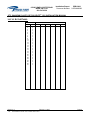
1
INSTALLATION
REPORT NO.
Document Number:
PPRI-3000
015PMAN0003
Aircraft Serial Number:
STC Number:
SA4005NM
SA00701SE
63354 POWELL BUTTE ROAD
BEND, OR 97701
800- 547-2558
Pulselite® Model 1210 / 2405-2A Installation Manual
FAA STC Number SA4005NM
FAA STC Number SA00701SE
NOTICE
These documents must be kept with the Aircraft Records
THIS DOCUMENT CONTAINS PROPRIETARY INFORMATION ON THE PRECISE FLIGHT, INC.
(PFI) COMPANY AND ITS RECEIPT OR POSSESSION DOES NOT CONVEY ANY RIGHTS TO
REPORDUCE, DISCLOSE ITS CONTENTS, OR TO MANUFACTURE, USE, OR SELL
ANYTHING IT MAY DESCRIBE.
REPORDUCTION, DISCLOSURE, OR USE WITHOUT
SPECIFIC WRITTEN AUTHORIZATION OF PFI IS STRICTLY FORBIDDEN.
Revision: J
File:
February 1, 2007
015PMAN0003J Pulselite 1210 Installation Manual.DOC
Page 1
63354 POWELL BUTTE ROAD
BEND, OR 97701
800- 547-2558
Installation Report:
Document Number:
PPRI-3000
015PMAN0003
STC SA4005NM, SA00701SE PULSELITE® 1210 INSTALLATION MANUAL
TABLE OF CONTENTS
Table of Contents ...................................................................................................................... 2
List of Tables ............................................................................................................................. 3
List of Figures ............................................................................................................................ 3
Revisions ................................................................................................................................... 4
List of Active Pages ................................................................................................................... 5
1.0 Overview.............................................................................................................................. 6
1.1 Introduction ...................................................................................................................... 6
1.2 Product Description.......................................................................................................... 6
1.2.1 Pulselite Control Unit Specifications .......................................................................... 7
1.3 Installation Overview ........................................................................................................ 7
1.4 Pulselite Model 1210 Installation Kit Contents ................................................................. 8
1.4.1 Unpacking and Inspection ......................................................................................... 8
1.5 How to Use This Manual and Read the Drawings............................................................ 8
1.5.1 Notes and Warnings .................................................................................................. 8
1.5.2 List of Abbreviations .................................................................................................. 9
1.5.3 Drawing Interpretation ............................................................................................... 9
1.5.4 Parts Lists................................................................................................................ 10
1.6 Manual Revisions........................................................................................................... 10
2.0 Installation Instructions ...................................................................................................... 11
2.1 General .......................................................................................................................... 11
2.2 Installation Approval Basis ............................................................................................. 11
2.3 List of Tools.................................................................................................................... 12
2.3.1 List of Supplies ........................................................................................................ 12
2.4 Pulselite Control Unit Installation ................................................................................... 12
2.4.1 Cooling Considerations ........................................................................................... 12
2.4.2 Control Unit Location Considerations ...................................................................... 12
2.4.3 Pulselite Control Unit Installation ............................................................................. 13
2.5 Electrical Installation ...................................................................................................... 14
2.5.1 Installation Considerations ...................................................................................... 14
2.5.2 Wiring Considerations ............................................................................................. 14
2.5.3 Control Unit Wiring .................................................................................................. 15
2.6 Switch Installation .......................................................................................................... 16
2.7 Diode Installation............................................................................................................ 17
2.8 Typical Installation Examples......................................................................................... 18
3.0 Testing............................................................................................................................... 20
3.1 Installation Testing ......................................................................................................... 20
3.2 EMI/FRI Testing ............................................................................................................. 20
3.2.1 Test Procedures ...................................................................................................... 21
3.2.2 Testing Conditions................................................................................................... 21
3.2.3 Ground Communications Test ................................................................................. 21
3.2.4 Ground Navigation Systems Test ............................................................................ 22
Revision: J
File:
February 1, 2007
015PMAN0003J Pulselite 1210 Installation Manual.DOC
Page 2
63354 POWELL BUTTE ROAD
BEND, OR 97701
800- 547-2558
Installation Report:
Document Number:
PPRI-3000
015PMAN0003
STC SA4005NM, SA00701SE PULSELITE® 1210 INSTALLATION MANUAL
3.2.5 Ground Weather Radar Test ................................................................................... 24
3.2.6 Ground Autopilot and Flight Director Test ............................................................... 24
3.2.7 Conclusion............................................................................................................... 25
4.0 Documentation .................................................................................................................. 26
5.0 Trouble Shooting Guide..................................................................................................... 27
5.1 Pulselite Fails To Operate.............................................................................................. 27
5.2 Additional Technical Assistance..................................................................................... 27
5.3 Return Authorization ...................................................................................................... 27
5.4 Warranty Service............................................................................................................ 27
LIST OF TABLES
Table 1- List of Abbreviations .................................................................................................... 9
Table 2 - Sample Parts List ..................................................................................................... 10
Table 3 - Tools Used ............................................................................................................... 12
Table 4 - Supplies Used .......................................................................................................... 12
Table 5 - Pulselite Wire............................................................................................................ 16
LIST OF FIGURES
Figure 1 - Third Angle Projection Example ................................................................................ 9
Figure 2 - Pulselite Control Unit Dimensions ........................................................................... 13
Figure 3 - Diode Installation..................................................................................................... 17
Figure 4 - Typical Installations ................................................................................................. 19
Figure 5 - Typical Installations ................................................................................................. 19
Figure 6 - Suggested FAA Form 337 Description of Work Statement ..................................... 26
Revision: J
File:
February 1, 2007
015PMAN0003J Pulselite 1210 Installation Manual.DOC
Page 3
63354 POWELL BUTTE ROAD
BEND, OR 97701
800- 547-2558
Installation Report:
Document Number:
PPRI-3000
015PMAN0003
STC SA4005NM, SA00701SE PULSELITE® 1210 INSTALLATION MANUAL
REVISIONS
-
Approved
By
CGL
Approved
Date
5/16/1989
-
-
CGL
9/18/1989
-
-
JFP
8/9/1991
-
-
DJT
5/12/1993
-
-
RPB
5/9/1994
-
-
STP
STP
8/27/1996
10/28/1996
-
-
STP
5/26/1999
-
-
EWL
11/22/1999
DJC
02/01/2007
JNS
5/16/2007
Rev.
DESCRIPTION OF CHANGES
Author
Date
A (1)
Original Release
Delete note on mounting location. Change weight
typing error
Removed mount bracket from DWG# PL-32478.
Eliminate wire spec. Mil-W-5086
Add updated AML dated 3/26/90
Redraw & Renumber DWG# PL-32478 to
000P043M dated 8/29/90
Minor word correction for clarity
Made minor corrections, changed physical DWG#
000P053M to reflect new heatsink design
Removed warranty statement
Removed STC & AFM Supplement, Move drawing
data to Appendix A, Include packing list
Changed model number
Changed installation instructions
Corrected DWG# 000P023M to show correct diode
placement
All pages Revised & Rewritten
Added list of Active Pages, Revised Page numbers.
Added text, added Continued Airworthiness
Added STC # for Robinson R22 & R44, Added
Robinson R22 & R44 packing list
Revised AC43.13-1A to -1B. Revised 337
statement.
Updated installation document format. Added how
to use manual and drawings section. Added
wiring & switch considerations. Added wiring
examples. Added Pass/Fail blocks to the EMI
RFI testing, Revised COMM. test blocks.
Removed Appendix with packing slip, and
installation drawing. ICA information moved to
PFI document 000PMAN0002.
-
B (2)
C (3)
D (4)
E (5)
F (6)
G (7)
H (8)
I (9)
J (10)
Revision: J
File:
February 1, 2007
015PMAN0003J Pulselite 1210 Installation Manual.DOC
Page 4
63354 POWELL BUTTE ROAD
BEND, OR 97701
800- 547-2558
Installation Report:
Document Number:
PPRI-3000
015PMAN0003
STC SA4005NM, SA00701SE PULSELITE® 1210 INSTALLATION MANUAL
LIST OF ACTIVE PAGES
ORIGINAL
PAGE
1
2
3
4
5
6
7
8
9
10
11
12
13
14
15
16
17
18
19
20
21
22
23
24
25
26
27
Revision: J
File:
REV
J
J
J
J
J
J
J
J
J
J
J
J
J
J
J
J
J
J
J
J
J
J
J
J
J
J
J
ADDED PAGES
PAGE
REV
PAGE
February 1, 2007
015PMAN0003J Pulselite 1210 Installation Manual.DOC
REV
PAGE
REV
Page 5
63354 POWELL BUTTE ROAD
BEND, OR 97701
800- 547-2558
Installation Report:
Document Number:
PPRI-3000
015PMAN0003
STC SA4005NM, SA00701SE PULSELITE® 1210 INSTALLATION MANUAL
1.0 OVERVIEW
1.1 INTRODUCTION
This manual contains information regarding the physical, mechanical, and electrical characteristics,
as well as installation information pertaining to the Precise Flight Pulselite® Model 1210 / 2405-2A
Control Unit. For maintenance and repair information, contact Precise Flight Inc.
1.2 PRODUCT DESCRIPTION
The Precise Flight Inc. Pulselite® system is a solid-state electrical switching unit that pulses the
aircraft’s existing external lights, such as the Landing, Taxi, Recognition, Logo, or Hover Lights.
The lights are pulsed in variety of patterns at 45 or 90 times per minute to create an illusion of
exaggerated motion. This illusion enhances aircraft recognition in flight, similar to the manner that
the flashing lights on an emergency vehicle do for automobiles.
The Pulselite® system does not effect normal operation of the aircraft lighting system. The
Pulselite simply bridges the existing aircraft light switches and/or relays allowing the pilot to turn on
his external lights at any time, by moving the original light switches to the ON position. When the
pilot switches the applicable external lights off and the Pulselite is switched to PULSE, the Pulselite
function will resume. The original external lighting switch(es), and any additional Pulselite control
switch(es), need to be switched off to extinguish the lights.
The Pulselite connects easily to an aircraft's external lighting system, and may be installed on a
wide variety of aircraft with differing light sequence combinations.
The control circuit of the Pulselite requires 12 or 24 VDC. The two controlled power circuits pulse
DC Power to the aircraft lamps with loads no greater than 125 Watts per channel (or approximately
10 Amps @ 12 VDC or approximately 10 Amps @ 24 VDC).
Precise Flight recommends that the landing lights be turned on steady (full time) when the aircraft
is within 200' AGL at night. Due to possible disorientation, the Pulselite should not be operated at
night in clouds or on the ground. The landing lights may be turned on steady by simply switching
the original landing/taxi/recognition lights on.
Revision: J
File:
February 1, 2007
015PMAN0003J Pulselite 1210 Installation Manual.DOC
Page 6
63354 POWELL BUTTE ROAD
BEND, OR 97701
800- 547-2558
Installation Report:
Document Number:
PPRI-3000
015PMAN0003
STC SA4005NM, SA00701SE PULSELITE® 1210 INSTALLATION MANUAL
1.2.1 Pulselite® Control Unit Specifications
•
•
•
Control Unit weight:
Cooling:
Dimensions:
•
•
•
Control Unit Operating Voltage:
Control Unit Operating Current:
Lamp – Capacity:
•
•
Available Lamp Outputs:
Pulse Frequency:
•
•
Ambient Operating Temp:
Sequence Operation:
.065 lb (0.29kg)
Radiation and Convection
4.75in (W), 3.0in (D), 1.25in (H)
12.06cm (W), 7.62cm (D), 3.18cm (H)
11VDC - 29VDC
0.02 Amps
125 Watts MAXIMUM per channel
10A Max @12VDC
5A Max @ 24VDC
2 Channels
Approximately 45 Pulses per minute – Low Rate
Approximately 90 Pulses per minute – High Rate
+5°F to +158°F (-15°C to +70º)
2 lights Alternating pulse
Or 2 lights pulsing Simultaneously
1.3 INSTALLATION OVERVIEW
1. Read through the entire manual, and become familiar with the drawings, before beginning any
part of the installation process.
2. Verify Pulselite installation kit (See section 1.4)
3. Mount the control unit to the aircraft.
4. Route and terminate the wires with the appropriate connectors.
5. Install the Pulselite circuit breaker and switches in the cockpit.
6. Functionally check the Pulselite® System.
7. Filling out necessary FAA paperwork and logbook entries to return the aircraft to service.
8. Complete and return the warranty card to Precise Flight, Inc.
Revision: J
File:
February 1, 2007
015PMAN0003J Pulselite 1210 Installation Manual.DOC
Page 7
63354 POWELL BUTTE ROAD
BEND, OR 97701
800- 547-2558
Installation Report:
Document Number:
PPRI-3000
015PMAN0003
STC SA4005NM, SA00701SE PULSELITE® 1210 INSTALLATION MANUAL
1.4 PULSELITE® MODEL 1210 INSTALLATION KIT CONTENTS
The Pulselite® Model 1210 / 2405-2A Kit may contain the following items.
Item Inventoried
Description
Pulselite Control Unit Model Unit
1
2
Copy of the Supplemental Type Certificate
3
Generic Rocker Switch
4
Fuse
Fuse Holder
5
6
Diode Set
7
Placard
8
Butt Splices
9
Ring Terminals
Installation Manual (This Manual)
10
11
Warranty Card
12
Screws and washers
13
Bundle Ties
1.4.1 Unpacking and Inspection
Exercise care when unpacking the equipment. Make a visual inspection of the unit for evidence of
damage incurred during shipment. If a claim for damage is to be made, save the shipping
container to substantiate the claim. The claim should be filed with the transportation company.
Retain the container and packaging material after the equipment has been removed, should
equipment storage or reshipment become necessary.
1.5 HOW TO USE THIS MANUAL AND READ THE DRAWINGS
1.5.1 Notes and Warnings
Because of the uniqueness of this installation in existing aircraft, Precise Flight has added notes,
cautions, and warnings to the installation manual.
NOTE
Notes are used to emphasize certain steps to prevent problems with the installation.
We, at Precise Flight, have added these notes to prevent problems before they occur
based on our experience installing these systems, or from ‘your’ feedback.
! CAUTION !
Cautions are used if aircraft damage can occur due to a missed step.
Please remember, we only have these in key locations based on previous
experience. It is the installer’s responsibility to make sure the installation is
done correctly, and to airworthiness standards.
!! WARNING !!
Warnings are used to emphasize a part of the installation where if done
incorrectly can pose a serious hazard to the installer or the pilot.
Revision: J
File:
February 1, 2007
015PMAN0003J Pulselite 1210 Installation Manual.DOC
Page 8
63354 POWELL BUTTE ROAD
BEND, OR 97701
800- 547-2558
Installation Report:
Document Number:
PPRI-3000
015PMAN0003
STC SA4005NM, SA00701SE PULSELITE® 1210 INSTALLATION MANUAL
1.5.2 List of Abbreviations
This section is to provide the reader with a complete state of the abbreviations used in this
document and installation.
Table 1- List of Abbreviations
A/R
AC
AOG
AMM
BL
CB
DC
FAA
FS or STA
IAW
ICA
IR
Lb, lbs
PCU or PLCU
PFI
MM
N/A or ‘-‘
N/C
SWPM
RETR
V
VAC
VDC
WDM
WL
WS
As Required
Advisory Circular
Aircraft On Ground
Airplane Maintenance Manual
Butt Line
Circuit Breaker
Direct Current
Federal Aviation Administration
Fuselage Station (Flight Station)
In Accordance With
Instructions for Continued Airworthiness
Initial Release
Pounds
Pulselite Control Unit
Precise Flight, Inc.
Maintenance Manual (Implies aircraft manufactures maintenance manual)
Not Applicable
No Connect
Standard Wiring Practices Manual
Retractable
Volts
Volts Alternating Current
Volts Direct Current
Wiring Diagram Manual
Water Line
Wing Station
1.5.3 Drawing Interpretation
All drawings produced by Precise Flight Inc, are based on ASME Y14.5-1994 standards,
measurements in Inches, and Third Angle Projection. Information on the drawings including notes,
parts, etc. are part of the FAA approved design and in most cases do include important installation
and manufacturing information.
Third Angle Projection is the method drawing views are produced as shown below.
Figure 1 - Third Angle Projection Example
(Earle, James “Engineering Design Graphics”)
Revision: J
File:
February 1, 2007
015PMAN0003J Pulselite 1210 Installation Manual.DOC
Page 9
63354 POWELL BUTTE ROAD
BEND, OR 97701
800- 547-2558
Installation Report:
Document Number:
PPRI-3000
015PMAN0003
STC SA4005NM, SA00701SE PULSELITE® 1210 INSTALLATION MANUAL
1.5.4 Parts Lists
A source of possible confusion when reading drawings is the proper interpretation of the parts list
or Bill of Materials (BOM). This STC includes multiple aircraft models and lamp/switch
configurations in the same drawing package. Because of the differences, special care must be
taken to make sure the correct installation is used.
-4
1
1
1
1
<1>
1
1
1
\
\
-3
-2
QTY REQD
<1>
1
1
\
-1
AS12007-2
EL02585
EL02749
-
SM-1000-003
X-E4N-300M
1N1184 DIODE KIT
1210
----DDM24W7SA197 (OR EQUIV)
3060S
----M83723/75W1610N
3060
----590P0003 (SHEET 4)
590P0003 (SHEET 3)
590P0003 (SHEET 2)
----590P0003-3
590P0003-2
590P0003-1
CODE
PART NO.
RELAY SOCKET
RELAY, NONLATCH, 2P, 5A
DIODE SET
PULSELITE CONTROL UNIT 1210
----CONNECTOR
PULSELITE CONTROL UNIT 3060S
----CONNECTOR
PULSELITE CONTROL UNIT 3060
----1210 WIRING DIAGRAM
3060S WIRING DIAGRAM
3060 WIRING DIAGRAM
----PULSELITE 1210 INSTALLATION
PULSELITE 3060S INSTALLATION
PULSELITE 3060 INSTALLATION
DESCRIPTION
(MIL-S-12883/52)
LEACH (OR SIMILAR)
------------(PART OF 3060S PULSELITE KIT)
--------(PART OF 3060 PULSELITE KIT)
------------------------------------MATERIAL/MFG.
18
17
16
15
14
13
12
11
10
9
8
7
6
5
4
3
2
1
ITEM
Table 2 - Sample Parts List
This chart shows the kit part number 590P0003-3 as an example.
Starting at line 3 of the Bill of Materials, from part number 590P0003-3, the installer moves to the
left until a “\” marks that applicable installation. Follow the -3 column up to see if another
installation or quantity of parts is required. Then follow the chart back to the right to find the
drawing/part number for the applicable installation. Some installations or diagrams listed as
optional are left to the discretion of the installing agency. Drawings are shown in this example, but
parts work on the same principle on the other installation drawings.
The Code numbers are PFI reference only inventory codes and do not supersede the part
numbers. The installations kit parts may be identified with by one or more of the following: drawing
number, PFI Code, or MS/NAS/AN number.
1.6 MANUAL REVISIONS
To ensure the maintenance of your existing aircraft fleet, possible revisions to this manual may
require updating over the life of the aircraft. Per the applicable Federal Aviation Regulations, an
update process is required to properly maintain these instructions in addition to the aircraft itself.
Because of this, it is imperative to complete the registration card for the aircraft once the system is
installed.
REVISIONS CAN BE MADE BY A SERVICE LETTER FROM PRECISE FLIGHT, AN AIRWORTHINESS DIRECTIVE AS
ISSUED BY THE ADMINISTRATOR, BY SINGLE PAGE UPDATES, OR A COMPLETE REPLACEMENT OF ALL PAGES
OF THE MANUAL. IT MUST BE CLEARLY NOTED AS TO THE REVISION LEVEL OF THE PAGES LISTED IN THE LIST
OF ACTIVE PAGES. IF A SINGLE SHEET(S) IS REPLACED, REPLACE THE LIST OF ACTIVE PAGES WITH THE NEW
ONE PROVIDED, OR UPDATE THE LIST MANUALLY AND INITIAL AND DATE THE LIST.
Revision: J
File:
February 1, 2007
015PMAN0003J Pulselite 1210 Installation Manual.DOC
Page 10
63354 POWELL BUTTE ROAD
BEND, OR 97701
800- 547-2558
Installation Report:
Document Number:
PPRI-3000
015PMAN0003
STC SA4005NM, SA00701SE PULSELITE® 1210 INSTALLATION MANUAL
2.0 INSTALLATION INSTRUCTIONS
Read all installation instructions prior to starting the installation or modifying the aircraft. If
necessary, please contact Precise Flight Incorporated at (541) 382-8684 and ask for Pulselite
assistance, or write us at the address above, if you have any questions.
2.1 GENERAL
This section contains interconnect diagrams, mounting dimensions, and other information
pertaining to a Pulselite installation.
NOTE
It is the installer’s responsibility to verify that the installation of the Pulselite®
Control system will not interfere with any existing modification on the aircraft
prior to starting the installation. Contact Precise Flight if there appears to be
an installation conflict.
2.2 INSTALLATION APPROVAL BASIS
The person who performs or supervises the installation of the Pulselite® Model 1210 / 2405-2A,
may be required to prepare FAA form 337. See Section 4 for a Sample Description of Work
Accomplished. Data that can be used as a basis for approval for return to service are:
A. AC 43.13-1B or later FAA approved revision: Acceptable Methods, Techniques and
Practices, Aircraft Inspection and Repair.
B. AC 43.13-2A or later FAA approved revision: Acceptable Methods, Techniques and
Practices, Aircraft Alterations
C. FAA approved Manufacturer's Installation Instructions.
Equipment installation procedures do not differ significantly among various aircraft. The installation
and operation of the Pulselite® Model 1210 / 2405-2A does not affect the aircraft operation or
performance.
The Sample Description of Work Accomplished, in Section 4 of this manual, is suggested language
provided as a convenience to the installing agency. The information and wording should be
modified to correctly describe the particular installation.
NOTE
Precise Flight Inc. can assume no responsibility for the alteration of the
airframe or electrical system.
NOTE
It is the responsibility of the installer to get all required approvals for the
parts of the installation that are outside the scope or design of the data
supplied per this STC.
Revision: J
File:
February 1, 2007
015PMAN0003J Pulselite 1210 Installation Manual.DOC
Page 11
63354 POWELL BUTTE ROAD
BEND, OR 97701
800- 547-2558
Installation Report:
Document Number:
PPRI-3000
015PMAN0003
STC SA4005NM, SA00701SE PULSELITE® 1210 INSTALLATION MANUAL
2.3 LIST OF TOOLS
Commonly used Tools for Pulselite Installation.
Table 3 - Tools Used
Abrasive Pad
AC 43.13-2B Chapter 11 (or later revision)
Deburring Tool
Drill Motor
Drills: Various
Pencil
Rivnut Insertion Tool
Ruler: 12 inch (minimum)
Screwdriver: Slot and Phillips #1 and #2 tip
Tape Measure: 2 feet minimum
Volt Ohmmeter
Wire Crimper, Cutter, and Stripper
Wrenches: Various
2.3.1 List of Supplies
Commonly used Supplies for Pulselite Installation:
Table 4 - Supplies Used
“Caterpillar” protective Grommet
Double Sided Tape
Bundle Ties
Lacing Cord
Teflon Sleeving
2.4 PULSELITE CONTROL UNIT INSTALLATION
Listed below are considerations to be examined before installing the Pulselite® Model 1210 / 24052A. Close attention to these suggestions will assure optimum performance when completed.
2.4.1 Cooling Considerations
Allow approximately ½” of space around the control unit for adequate convective cooling. This is
required so the heat sink fins may dissipate heat at the proper rate. Make every effort to locate
control unit away from heat sources, as elevated operating temperatures reduce reliability.
2.4.2 Control Unit Location Considerations
A. Select a location for the Pulselite Control Unit which is suitably ventilated for avionics.
!! WARNING !!
The Pulselite Model 1210 / 2405-2A is not approved for use in a potentially
explosive environment (refer to AC 43.13-2B or later FAA approved revision,
Chapter 2 - Radio Installation) Locate Pulselite away from fire hazard zones,
highly explosive or corrosive areas, potentially hazardous fluid areas; e.g.
water, fuel, hydraulic fluid, or oxygen units, etc.
®
B. The Pulselite Control unit must be installed in a structurally substantiated location. If a location
is already defined for your specific aircraft make and model per the PFI STC drawing package,
this is an approved location. All other locations require a separate approval; this is the
responsibility of the installer.
Revision: J
File:
February 1, 2007
015PMAN0003J Pulselite 1210 Installation Manual.DOC
Page 12
63354 POWELL BUTTE ROAD
BEND, OR 97701
800- 547-2558
Installation Report:
Document Number:
PPRI-3000
015PMAN0003
STC SA4005NM, SA00701SE PULSELITE® 1210 INSTALLATION MANUAL
C. Avoid mounting the Pulselite Control unit in potentially wet locations such as gear wells or in a
belly compartment subject to splash.
2.4.3 Pulselite Control Unit Installation
TOOLS REQUIRED
Abrasive Pad
E Size Drill, Drill
Deburring Tool
Aircraft Maintenance/Service Manual
Part Number
Qty
1210 (PFI p/n 015P001A-2)
1
4
4
4
4
PARTS REQUIRED
Description
Model 1210 Pulselite Control Unit
Screws
Nuts or Lock nuts
Washers
Lock Washers
Screwdriver Philips #2
-
PFI Code Number
-
The Pulselite Control Unit can be installed in any axis. If the Pulselite Control Unit is mounted on a
vertical surface, install the unit using the four (4) supplied pan head screws, nuts and washers
supplied with kit, or equivalent screws and nutplates. Burnish at least one fastener location to
insure proper ground.
4.78
[121.29]
4.45
[113.03]
(REF)
3.00
[76.20]
2.50
[63.50]
(REF)
0.25
[6.35]
(REF)
1.23
[31.12]
Figure 2 - Pulselite Control Unit Dimensions
Revision: J
File:
February 1, 2007
015PMAN0003J Pulselite 1210 Installation Manual.DOC
Page 13
63354 POWELL BUTTE ROAD
BEND, OR 97701
800- 547-2558
Installation Report:
Document Number:
PPRI-3000
015PMAN0003
STC SA4005NM, SA00701SE PULSELITE® 1210 INSTALLATION MANUAL
2.5 ELECTRICAL INSTALLATION
2.5.1 Installation Considerations
Lamps to pulse: Landing lights are the most commonly pulsed lamps due to their higher output.
Taxi, Recognition and Wingtip lights may also be pulsed, or a combination of any. Pulsing
Navigation lights is not advised.
Pulsing a Landing and Taxi lights mounted immediately adjacent to each other in the aircraft’s
nose may, at a distance, merely seem to flicker when pulsed in the Alternate, or wig-wag mode. It
is advisable to pulse lamps closer than one and one-half feet apart in the Simultaneous mode, i.e.
on and off at the same time. Greater separation between pulsed lamps provides better
conspicuity.
The Alternate mode will also be easier on the aircrafts electrical system. Two 125 watt lamps
illuminated at alternate times result in a single constant 4 ½ amp load to a 28 volt aircraft. The
resulting overall load to the electrical system is less than that produced when turning both lamps
on steady. The same two lamps pulsing simultaneously will cause an 9 amp load to pulse on and
off. This may cause some interior lamps to dim and the ammeter needle to jump. While this
should not present a problem or real cause for concern, it may be distracting.
Some lighting circuits may be easier to wire for the Simultaneous mode. For example, wiring a
single channel or two paralleled Pulselite channels, in the Simultaneous mode is the easiest way to
pulse two wing tip lights wired to a single pole toggle switch. To pulse the same lights in the
Alternate mode, either install a two pole switch or install two diodes to isolate the lamps.
If pulsing gear mounted or other retractable lights, additional circuitry may be required to prevent
the light from being illuminated when the gear is retracted or the lamp is in an enclosed
compartment. Care must also be exercised to prevent the extend/retract motors from being
pulsed.
2.5.2 Wiring Considerations
All wiring must be secured to prevent chafing and faulting connections. Refer to FAA AC43.13-2B,
or later FAA approved revision, for wiring installation best practices.
NOTE
Precise Flight recommends Mil-W-22759 wiring be used in the Pulselite
Installation.
!! WARNING !!
Do Not Use Aluminum Wire for the Pulselite Installation.
The Pulselite installation requires certain wiring precautions in addition to the standard wiring
practices for the aircraft.
A. Observe proper cable routing, i.e. avoid tie-wrap joining power lines to antenna leads. Avoid
close proximity to navigation equipment. Where it is necessary to cross Pulselite wiring over
Revision: J
File:
February 1, 2007
015PMAN0003J Pulselite 1210 Installation Manual.DOC
Page 14
63354 POWELL BUTTE ROAD
BEND, OR 97701
800- 547-2558
Installation Report:
Document Number:
PPRI-3000
015PMAN0003
STC SA4005NM, SA00701SE PULSELITE® 1210 INSTALLATION MANUAL
other wires, cross at a right angle and avoid running lamp supply or output wires in parallel to
radio, communication equipment or storm scope wiring. Ensure an adequate ground for the
Pulselite Control unit and its case.
B. Be sure that all connections are sound, i.e. avoid frayed or split conduit ends. Poor, loose or
corroded connections can cause electrical noise and degraded operation.
C. Avoid sharp bends or undue strain on cables.
2.5.3 Control Unit Wiring
After the Pulselite Control Unit has been properly mounted, determine the lighting pulse mode.
Find the total wattage of the lamp(s) connected to the Pulselite Control Unit. Divide the highest
total wattage by the voltage. The result will be the highest amperage rating on the Pulselite
Control Unit. Amperages should not exceed 10 amps per channel @ 12 VDC or 5 amps per
channel @ 24 VDC or 125 Watts per channel. See Example below.
50W
= 4.16 A
12VDC
Determine the amperage on individual channels. Proper wire and circuit protection should be
observed.
•
Approved wire specification is MIL-W- 22759/16 or equivalent.
•
Fuse specification is MIL-F-15160 or equivalent.
•
Circuit breaker specification is MIL-C-5809 or equivalent.
A. GROUND: To protect the Pulselite control unit and insure proper installation, it is important
to check that the ground wire (black wire) is properly grounded to the aircraft frame.
Chassis of unit should be mounted to airframe and interfaces burnished to ensure a good
ground. If the Pulselite Control Unit cannot be mounted to A/C structure, attach a bonding
jumper per AC43.13-1B or later FAA approved revision Section 3 Par. 452.
B. CONTROL POWER: Power input for the Pulselite Control Unit is through the white wire.
Use at least 22 gauge wire for this circuit. To protect this wire, a circuit breaker or inline
fuse is required. This circuit breaker or fuse should not exceed 1 to 5 amps. This protected
control power may come off the existing lamp control switch if room is not available in the
circuit breaker panel.
C. PULSE RATE SELECT: Making a connection between the two brown wires will change the
rate of pulse from approximately 45 pulses per minute to approximately 90 pulses per
minute. If the pulse rate is left at 45, cap and stow the two brown wires.
D. MODE SELECT: Making a connection between the gray wire and the violet wire will pulse
the two connected lights alternately. Making a connection between the gray wire and the
orange wire will pulse the lights simultaneously.
E. LAMP INPUT POWER: The red wire is attached to either an existing external light circuit
breaker or a new circuit breaker of the same value as the existing external light circuit
Revision: J
File:
February 1, 2007
015PMAN0003J Pulselite 1210 Installation Manual.DOC
Page 15
63354 POWELL BUTTE ROAD
BEND, OR 97701
800- 547-2558
Installation Report:
Document Number:
PPRI-3000
015PMAN0003
STC SA4005NM, SA00701SE PULSELITE® 1210 INSTALLATION MANUAL
breakers. Refer to Typical Installation Examples. Fuse holders are not recommended
for Lamp Input Power.
F. CHANNEL 1 OUTPUT: The yellow wire is attached to an aircraft external light.
G. CHANNEL 2 OUTPUT: The blue wire is attached to an aircraft external light.
H. Cap and stow all wires not utilized in the installation.
I.
Route wires neatly and tie wrap to complete electrical installation.
PULSELITE WIRE TABLE
COLOR
RED
YELLOW
BLUE
WHITE
BROWN
BROWN
BLACK
ORANGE
GRAY
VIOLET
GAUGE
12
16
16
22
22
22
22
22
22
22
FUNCTION
LAMP INPUT POWER
CHANNEL 1 OUTPUT
CHANNEL 2 OUTPUT
CONTROL UNIT POWER
PULSE RATE SELECT
PULSE RATE SELECT
GROUND
SIMULTANOUS MODE
MODE SELECT
ALTERNATE MODE
Table 5 - Pulselite Wire
2.6 SWITCH INSTALLATION
In general, it is preferable to retain original switch functionality. An existing landing light switch,
supplemented with an additional Pulselite switch, is easily operated by a pilot familiar with the
aircraft but not the Pulselite system.
The wide variety of switch styles used makes it impossible for Precise Flight to supply an
appropriate switch for every aircraft. An ON-OFF switch is provided with the Pulselite kit however
it may be preferable to install a customer supplied switch that more closely matches the existing
aircraft switch style. An ON-OFF rocker or toggle switch similar to the existing Landing light switch
may be installed for Pulselite control.
Where panel space is at a premium, a two position ON-OFF Landing, Taxi or Recognition light
switch can usually be replaced with a three position ON-OFF-PULSE switch. For systems using
circuit breaker switches, a separate breaker switch would be required. These switches must have
a lamp load rating appropriate for the light to be pulsed. Due to the high inrush associated with
incandescent lamps, the lamp load rating of a switch may be 20-25% of the listed resistive load
rating.
A. A switch is required for activation of the Pulselite Control Unit. The switch should be
rated for 3 amps at 12 or 28 VDC.
B. The switch(es) should be located near the existing aircraft landing light switches.
Revision: J
File:
February 1, 2007
015PMAN0003J Pulselite 1210 Installation Manual.DOC
Page 16
63354 POWELL BUTTE ROAD
BEND, OR 97701
800- 547-2558
Installation Report:
Document Number:
PPRI-3000
015PMAN0003
STC SA4005NM, SA00701SE PULSELITE® 1210 INSTALLATION MANUAL
C. Install placard (supplied with kit) next to switch. You may have your instrument panel
engraved to provide switch identification.
2.7 DIODE INSTALLATION
High current diodes are supplied with some Pulselite kits to isolate the outputs where appropriate.
The use of diodes is not usually required when using a two pole switch, or when pulsing both
lamps simultaneously.
Where a single pole switch is used to control two lamps that are to be pulsed alternately, the
diodes prevent one channel from feeding back to the common switch connection and lighting both
lamps at the same time. The diodes are installed between the switch and the lamps, with the
Pulselite output wires on the lamp side of the diode. Power flows through both diodes to illuminate
both lamps when the light switch is in the steady on position.
Some aircraft use a mechanically interlocking switch, or a switch and diode arrangement to
illuminate both landing and taxi lights when the switch is in the landing position. A single diode
would be required in this case to prevent pulsed power to the landing light from feeding power to
the taxi light as well.
If the Pulselite is used to pulse two lamps, normally fed from differing busses of a multiple buss
system, a diode must be installed to prevent voltage from the Pulselite’s lamp input power (Red
wire) from back-feeding into the other buss.
The body of the stud mounted diodes provided is electrically hot, with the threaded stud being the
cathode connection. Because battery voltage will be present on the diode, it must not be allowed
to come in contact with metal or other wiring. When diodes are required, it is recommended they
be mounted on a phenolic insulator secured to the aircraft. This phenolic insulates the diodes from
aircraft ground and from each other. Heavy current through the diodes can cause them to become
very hot, use a heat resistant material, not acrylic.
1N1184 DIODE
35A 100V MIN. (OR SIMILAR)
INSULATOR
TO
LIGHTS
FROM
SWITCH
OUTPUT (CATHODE)
INPUT (ANODE)
PLEASE NOTE: WHEN DIODES ARE USED THE ENTIRE DIODE
ASSEMBLY MUST BE INSULATED FROM AIRCRAFT GROUND.
Figure 3 - Diode Installation
Revision: J
File:
February 1, 2007
015PMAN0003J Pulselite 1210 Installation Manual.DOC
Page 17
Installation Report:
Document Number:
63354 POWELL BUTTE ROAD
BEND, OR 97701
800- 547-2558
PPRI-3000
015PMAN0003
STC SA4005NM, SA00701SE PULSELITE® 1210 INSTALLATION MANUAL
2.8 TYPICAL INSTALLATION EXAMPLES
The following are only a few of many possible wiring scenarios.
a.) ADDITIONAL PULSELITE SWITCH INSTALLED
(EXISTING AIRCRAFT WIRING)
LIGHT CB
PULSELITE CB
LANDING
3A
ORANGE
GRAY
VIOLET
WHITE
PULSE
RED
1200 SERIES
PULSELITE
YELLOW
BLUE
b.) EXISTING SWITCH REPLACED WITH 3 POSITION STEADY-OFF-PULSE SWITCH
STEADY
OFF
PULSE
LIGHT CB
WHITE
ORANGE
GRAY
VIOLET
5A MAX
RED
1200 SERIES
PULSELITE
HIGH
WATTAGE
LAMP
YELLOW
BLUE
c.) LANDING LIGHT SWITCH REPLACED WITH 3 POSITION SWITCH
ALTERNATE OR SIMULTANEOUS MODE
TAXI CB
DIODES MAY BE REQUIRED ON
ONE OR BOTH LAMP WIRES TO
PREVENT CROSSED BUSSES
TAXI
LANDING
LANDING CB
STEADY
OFF
PULSE
ORANGE
GRAY
VIOLET
WHITE
5A MAX
PULSELITE CB
RED
1200 SERIES
PULSELITE
d.) 2 LIGHT SYSTEM WITH PULSELITE SWITCH
LANDING SWITCH TURNS ON LANDING & TAXI LIGHTS
TAXI CB
PULSE
CONTROL CB
LANDING
5A MAX
NEW DIODE
REQUIRED FOR
ALTERNATE PULSE
(ORIGINAL EQUIPMENT DIODE
UTILIZED IN SOME SYSTEMS)
WHITE
PULSE
PULSELITE CB
Revision: J
File:
BLUE
AN ADDITIONAL ISOLATION DIODE MAY
BE REQUIRED TO PREVENT PULSELITE
CB FROM BACK-FEEDING OTHER BUSS
TAXI
LANDING CB
YELLOW
RED
1200 SERIES
PULSELITE
February 1, 2007
015PMAN0003J Pulselite 1210 Installation Manual.DOC
ORANGE
GRAY
VIOLET
YELLOW
BLUE
Page 18
63354 POWELL BUTTE ROAD
BEND, OR 97701
800- 547-2558
Installation Report:
Document Number:
PPRI-3000
015PMAN0003
STC SA4005NM, SA00701SE PULSELITE® 1210 INSTALLATION MANUAL
Figure 4 - Typical Installations
e.) WINGTIPS WITH 1 POLE SWITCH
LIGHT CB
WINGTIP
NEW DIODES REQUIRED
FOR ALTERNATE PULSE
PULSELITE CB
3A
ORANGE
GRAY
VIOLET
WHITE
PULSE
RED
1200 SERIES
PULSELITE
YELLOW
BLUE
f.) WINGTIPS WITH 2 POLE SWITCH
LIGHT CB
5A MAX
WHITE
STEADY
OFF
PULSE
ORANGE
GRAY
VIOLET
RED
1200 SERIES
PULSELITE
YELLOW
BLUE
g.) ADDITIONAL PULSELITE CIRCUIT BREAKER SWITCH INSTALLED
LANDING
LIGHT CB
PULSE
ORANGE
GRAY
VIOLET
5A MAX
PULSELITE CB
WHITE
RED
MATCH EXISTING LT CB
1200 SERIES
PULSELITE
YELLOW
BLUE
h.) EXISTING CONTROL SWITCH REPLACED WITH 3 POSITION SWITCH
LIGHT CB
CONTROL CB
5A
MAX
STEADY
OFF
PULSE
WHITE
ORANGE
GRAY
VIOLET
RED
1200 SERIES
PULSELITE
YELLOW
BLUE
Figure 5 - Typical Installations
Revision: J
File:
February 1, 2007
015PMAN0003J Pulselite 1210 Installation Manual.DOC
Page 19
63354 POWELL BUTTE ROAD
BEND, OR 97701
800- 547-2558
Installation Report:
Document Number:
PPRI-3000
015PMAN0003
STC SA4005NM, SA00701SE PULSELITE® 1210 INSTALLATION MANUAL
3.0 TESTING
3.1 INSTALLATION TESTING
The following test procedure will evaluate the installation in the aircraft:
1.
2.
3.
4.
5.
6.
Check connections and wiring before applying power
Insure the grey wire is attached to either the violet or orange wire, with remaining wire
capped.
Turn aircraft power ON.
With the existing Landing / Taxi / Recognition Light Switch OFF, Switch the Pulselite
Unit to ON and verify that the appropriate Landing / Taxi / Recognition Lights are flashing
on the aircraft.
Switch the appropriate Landing/ Taxi / Recognition Lights ON utilizing the existing switch
and verify that the lights remain on without flashing.
Switch the Pulselite Control Unit and the existing Landing/ Taxi / Recognition Light
switches OFF and verify that the Landing/ Taxi/ Recognition Lights are OFF.
3.2 EMI/FRI TESTING
The following is an outline for determining that no detrimental Electro Magnetic Interference (EMI)
or Radio Frequency Interference is caused by the installation of a Precise Flight Pulselite product
per FAR §23.1431, §25.1431, §27.1431, or §29.1431.
These procedures are not necessarily all encompassing in that they may not include all of the
equipment installed in the airplane. If electronic and navigation equipment is installed which is not
included in this document, consult the equipment manufacturer, an FAA approved repair station
rated in the equipment involved ,or an FAA Avionics Inspector for applicable test procedures.
The evaluation will be with a series of equipment checks, on the ground, to determine that no
detrimental EMI/RFI effects are introduced into the aircraft by the Pulselite system.
The electrical systems installed in the aircraft will be referred to as the Pulselite system in this
procedure.
The following tests should be performed by personnel familiar with aircraft systems and proper
operation as well as the Pulselite equipment and its proper operation.
Any and all discrepancies shall be noted. Any discrepancies noted during these procedures must
be reported to Precise Flight, Inc. and evaluated for cause, extent and as to what corrective action
should be taken to correct the problem. The aircraft may not be flown after discrepancies are
found unless the Pulselite system is disconnected at the aircraft bus until such time as the
problems have been corrected and the aircraft has successfully passed the ground portion of this
test. Only then may the aircraft be flown to complete this test.
A record of this test must be recorded in the aircraft logbook. The entry should include date,
aircraft time, and results including any discrepancies note. The ground test results shall be
recorded in the permanent aircraft records by the installing mechanic or a mechanic with the
proper ratings. A copy of the following pages with the test results is recommended to be kept as
Revision: J
File:
February 1, 2007
015PMAN0003J Pulselite 1210 Installation Manual.DOC
Page 20
63354 POWELL BUTTE ROAD
BEND, OR 97701
800- 547-2558
Installation Report:
Document Number:
PPRI-3000
015PMAN0003
STC SA4005NM, SA00701SE PULSELITE® 1210 INSTALLATION MANUAL
part of the aircraft permanent records to show passing EMI/RFI testing is completed on this
installation.
3.2.1 Test Procedures
During the following tests, the aircraft shall be supplied with adequate aircraft power at or above
the minimum bus voltage for the aircraft. The airplane should be located for proper radio reception
and radar operation, usually outside.
NOTE
The Landing Lights generate significant heat; take all necessary
precautions to safeguard personnel and equipment.
3.2.2 Testing Conditions
1.
The Stand-by magnet compass test will require a clear area to turn the aircraft and will
require a tug or aircraft power to rotate.
2.
The weather radar check will require suitable clear area since the radar will be operated as
part of the test.
3.
Many of the RFI / EMI tests require the observation of system indicators while turning the
Pulselite system ON and OFF. These can be performed during an already planned engine
run and control surface check, if applicable.
3.2.3 Ground Communications Test
1. Select Comm. 1 to a local frequency in the lower end of the COMM frequency band. Check for
clarity of reception and background noise with all Pulselite® equipment operating. Repeat for all
Comm radios.
Remarks:
PASS:
FAIL:
Initial:
Date:
2. Select Comm. 1 to a local frequency in the upper end of the COMM frequency band. Check for
clarity of reception and background noise with all Pulselite® equipment operating. Repeat for all
Comm radios.
Remarks:
PASS:
Revision: J
File:
FAIL:
February 1, 2007
015PMAN0003J Pulselite 1210 Installation Manual.DOC
Initial:
Date:
Page 21
63354 POWELL BUTTE ROAD
BEND, OR 97701
800- 547-2558
Installation Report:
Document Number:
PPRI-3000
015PMAN0003
STC SA4005NM, SA00701SE PULSELITE® 1210 INSTALLATION MANUAL
3. Select Comm. 2 to a local frequency in the lower end of the COMM frequency band. Check for
clarity of reception and background noise with all Pulselite® equipment operating. Repeat for all
Comm radios.
Remarks:
N/A:
PASS:
FAIL:
Initial:
Date:
4. Select Comm. 2 to a local frequency in the upper end of the COMM frequency band. Check for
clarity of reception and background noise with all Pulselite® equipment operating. Repeat for all
Comm radios.
Remarks:
N/A:
PASS:
FAIL:
Initial:
Date:
5. Verify that the intercom is free from noise and interference caused by the Pulselite®
installation.
Remarks:
N/A:
PASS:
FAIL:
Initial:
Date:
6. Set the HF radio to 4 MHz, 9.4 MHz, 14.8 MHz, 20.2 MHz, 22.99 MHz. Check for clarity of
reception and background noise with the Pulselite® system operating. Check that the HF is not
®
interfered with, or interferes with the Pulselite emission.
Remarks:
N/A:
PASS:
FAIL:
Initial:
Date:
3.2.4 Ground Navigation Systems Test
1.
VOR/DME
a. Select VOR NAV 1 receiver to a local frequency, center CDI needle of HSI / CDI with
"TO" indication. Listen for background noise.
b. Switch Pulselite® equipment on and off, check for interference and needle deviation.
c. Repeat for all other VHF NAV radios.
d. Tune VOR NAV 1 to a local VORTAC station with Pulselite® equipment off. Note
distance on DME and listen for noise. Turn Pulselite® equipment on and compare
distance readings and background noise.
e. Repeat for all other VHF NAV radios.
Remarks:
N/A:
Revision: J
File:
PASS:
FAIL:
February 1, 2007
015PMAN0003J Pulselite 1210 Installation Manual.DOC
Initial:
Date:
Page 22
63354 POWELL BUTTE ROAD
BEND, OR 97701
800- 547-2558
Installation Report:
Document Number:
PPRI-3000
015PMAN0003
STC SA4005NM, SA00701SE PULSELITE® 1210 INSTALLATION MANUAL
2. Loran C
a. Observe Loran self test responses and signal to noise ratios. Turn Pulselite equipment
on and recycle Loran and compare results.
Remarks:
N/A:
PASS:
FAIL:
Initial:
Date:
3. RNAV
a. VOR MODE - Set to VHF on a local frequency, center CDI and pilots HSI / CDI, turn on
Pulselite® equipment and check for interference.
Remarks:
N/A:
PASS:
FAIL:
Initial:
Date:
b. DME MODE - With Pulselite® equipment off, set to local VHF frequency and note DME
reading. Turn on Pulselite® equipment and compare DME reading. Verify reading with
known distance.
Remarks:
N/A:
PASS:
FAIL:
Initial:
Date:
c. RNAV MODE - With Pulselite® equipment off, set local VHF frequency, set waypoint
bearing to 180 and waypoint distance to 25 miles. Center CDI and note RNAV readings.
Turn Pulselite® equipment on and note any changes in RNAV readings.
Remarks:
N/A:
PASS:
FAIL:
Initial:
Date:
4. GPS
a.
b.
c.
d.
Select NAV Page - go to Satellite Status Page.
Find Signal Strength.
Monitor Signal Strength.
Turn Pulselite® equipment on and monitor Signal Strength readings and watch for signal
strength variations.
e. GPS Position Page - check for position errors with Pulselite in operation.
Remarks:
N/A:
Revision: J
File:
PASS:
FAIL:
February 1, 2007
015PMAN0003J Pulselite 1210 Installation Manual.DOC
Initial:
Date:
Page 23
63354 POWELL BUTTE ROAD
BEND, OR 97701
800- 547-2558
Installation Report:
Document Number:
PPRI-3000
015PMAN0003
STC SA4005NM, SA00701SE PULSELITE® 1210 INSTALLATION MANUAL
5. Magnetic Compass
a. With Pulselite® equipment OFF, note compass heading. Turn Pulselite® equipment ON
and compare compass heading.
NOTE
This Test Must Be Repeated With The Aircraft Headed In Four
Directions Approximately 90° Apart.
Heading
Pulselite ON
Pulselite OFF
Position 1
Compass Readings
Position 2
Position 3
Position 4
Remarks:
N/A:
PASS:
FAIL:
Initial:
Date:
3.2.5 Ground Weather Radar Test
!! WARNING !!
USE CAUTION WHEN OPERATING RADAR! FOLLOW RADAR
MANUFACTURERS RECOMMENDATIONS FOR SAFETY.
Select "WxRadar ON". After proper warm up time, select "TEST” mode and confirm proper operation.
Select "MAP" mode and note display. Turn on Pulselite® equipment and note any changes.
Remarks:
N/A:
PASS:
FAIL:
Initial:
Date:
3.2.6 Ground Autopilot and Flight Director Test
Turn on autopilot and perform ground check per the autopilot manufacturer’s instructions in the flight
manual. Turn on the Pulselite® equipment and again perform check. Note any discrepancies. Check
the Flight Management Computer for errors on a RNAV and VOR Approach.
Remarks:
N/A:
Revision: J
File:
PASS:
FAIL:
February 1, 2007
015PMAN0003J Pulselite 1210 Installation Manual.DOC
Initial:
Date:
Page 24
63354 POWELL BUTTE ROAD
BEND, OR 97701
800- 547-2558
Installation Report:
Document Number:
PPRI-3000
015PMAN0003
STC SA4005NM, SA00701SE PULSELITE® 1210 INSTALLATION MANUAL
3.2.7 Conclusion
EMI/RFI Passing Test Data Record
Date:
Make:
Model:
Ser. No:
Witness:
Location:
Date:
Remarks:
Revision: J
File:
February 1, 2007
015PMAN0003J Pulselite 1210 Installation Manual.DOC
Page 25
63354 POWELL BUTTE ROAD
BEND, OR 97701
800- 547-2558
Installation Report:
Document Number:
PPRI-3000
015PMAN0003
STC SA4005NM, SA00701SE PULSELITE® 1210 INSTALLATION MANUAL
4.0 DOCUMENTATION
Before performing flight tests it is recommended you complete the calculations for weight and
balance for 1 lb at the appropriate FS for the specific aircraft model and revise the equipment
list showing installation of Precise Flight Pulselite® System. FAA Form 337, section 8
“Description of Work Accomplished”.
8. Description of Work Accomplished
(If more space is required, attach additional sheets. Identify with aircraft nationality and registration mark and date work completed.)
A. The following components were installed:
Precise Flight Pulselite® Model 1210/2405-2A System STC # _________. Precise
Flight Installation Kit Number _____________.
B. Installed the Model 1210/2405-2A Pulselite® in accordance with Pulselite®
Installation Manual, PFI Document Number 015PMAN0003 Revision __ and
guidance in FAA Advisory Circulars 43.13-1B, chapter 11, and 43.13-2A, Chapter 1
& 2. (Or later revisions.)
C. An electrical load analysis was performed and the revised continuous load of the
aircraft electrical bus does not exceed 80% of capacity.
D. A complete operational test was performed according to the Pulselite® Installation
Manual, Model 1210 / 2405-2A Report number 015PMAN0003 Rev ___ dated
_________ The equipment performed satisfactorily and did not adversely affect
existing components or systems in the aircraft, as required by FAR 23.1301, FAR
23.1431 (or FAR 25.1301, FAR 25.1431, FAR 27.1301, FAR 27.1431, FAR
29.1301, FAR 29.1431 as applicable).
E. The aircraft equipment list was revised to reflect these changes; weight and balance
data was revised and placed in the aircraft records. A Precise Flight Inc. Pulselite®
Aircraft Flight Manual Supplement dated ________ was placed in the aircraft.
Figure 6 - Suggested FAA Form 337 Description of Work Statement
•
Add the FAA approved Flight Manual Supplement to the aircraft Flight manual.
•
Keep all Precise Flight Pulselite® papers with aircraft records.
•
Fill out and return warranty card to Precise Flight Inc.
Revision: J
File:
February 1, 2007
015PMAN0003J Pulselite 1210 Installation Manual.DOC
Page 26
63354 POWELL BUTTE ROAD
BEND, OR 97701
800- 547-2558
Installation Report:
Document Number:
PPRI-3000
015PMAN0003
STC SA4005NM, SA00701SE PULSELITE® 1210 INSTALLATION MANUAL
5.0 TROUBLE SHOOTING GUIDE
5.1 PULSELITE FAILS TO OPERATE
a.
b.
c.
d.
Check Circuit Breakers and/or in-line fuse.
Check Connectors & Terminals for Security and Contact Insertion.
Check Wiring Diagram against Aircraft Installation.
Perform Installation Checkout per Section 3.1
If the Pulselite is found to be inoperative, do not cut wires immediately next to the unit. If it
is necessary to cut wires to remove the Pulselite control, leave at least a 6-12” pigtail.
Without these wires, a new wire harness must be installed for testing and repair at
additional expense.
5.2 ADDITIONAL TECHNICAL ASSISTANCE
Please call Precise Flight, Inc. Toll Free from inside the United States at 1-800-547-2558; or
internationally or locally at 541-382-8684.
5.3 RETURN AUTHORIZATION
In order to expedite repair of units, call the factory for a return authorization number before
returning equipment for service.
5.4 WARRANTY SERVICE
Precise Flight warrants products in accordance with the warranty statement in effect at the
time of equipment registration. All repairs are performed at the factory. Contact Precise
Flight, Inc. for a warranty/return authorization. All requests for warranty payment must be
submitted on a standard warranty claim form, accompanied by the dealer invoice.
Authorized warranty work performed by the dealer will be limited to removal and reinstallation of units on an exchange basis. Precise Flight Inc. will bear the cost of warranty
returns both ways via UPS surface delivery only. Precise Flight reserves the right to use
reconditioned parts in repairing the product or to use reconditioned units as warranty
replacements.
Revision: J
File:
February 1, 2007
015PMAN0003J Pulselite 1210 Installation Manual.DOC
Page 27