1
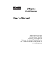
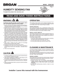
IC SystemTM Interface Installation Guide July 2009 IMPORTANT NOTES: INSTALLING THE ICI – Integrated Control Interface .................. 3 Installation Checklist........................................................................................................ 4 Verify Contents of the Packing Box ................................................................................. 5 Choose Location to Mount the ICI ................................................................................... 6 Gather Installation Tools ................................................................................................. 7 Mount Controller.............................................................................................................. 8 Connect Field Wiring ....................................................................................................... 9 Connect Source Power ................................................................................................. 10 Complete Installation..................................................................................................... 11 2 IC System™ Installation Guide IMPORTANT NOTES: INSTALLING THE ICI – Integrated Control Interface This section explains how to mount the ICI controller on the wall and connect the wiring. NOTE: The ICI controller must be installed in compliance with all electrical codes and must be installed indoors. NOTE: The installation of the ICI controller should be done with power supply disconnected. NOTE: Do not connect the USB cable to the central control computer until the Central Control software has been loaded. Specific drivers are required to operate the IC Interface through the Central Control. NOTE: For the first two minutes after the wire path has been activated, there will not be any operation or response from the field ICMs. WARNING: Field wire paths must be kept separate from other wire paths. Do not connect the field wires together from different output (group) wire paths. IC System™ Installation Guide 3 Installation Checklist We recommend you complete the following steps in order to properly install the ICI controller. For your convenience, a check-off box has been provided for each step. Verify the contents of the packing box. Choose a location to mount the ICI in the building. Gather installation tools Obtain Mounting Hardware and attach the controller to the wall Connect field wiring Connect power supply Install version 7.0 or later of the central control software in the computer. Attach USB cable after version 7.0 or later central control software is loaded Complete the installation 4 IC System™ Installation Guide Verify Contents of the Packing Box ICI Controller Keys Rain Bird Installation Guide Mounting Template In some markets the following will also be included: - power supply cord - USB cable (If these cables are not included in the box, please contact your distributor.) IC System™ Installation Guide 5 Choose Location to Mount the ICI Choose an indoor location that: Is easily accessible Allows for comfortable viewing Has a flat wall surface Is near a 100V, 120 V or 230/240 V AC power source, depending on model Is located within 5 feet (1.5 meters) of the Central Control computer – this can be increased up to 25 feet (7.5 meters) with a longer USB cable (not supplied) NOTE: codes. This controller must be installed in compliance with electrical 15 in (38.1cm) min 14.3 in (36.4 cm) 12.7 in (32.2 cm) Wall Eye Level 5.5in (14cm) Cabinet Depth Power Cord for ICI Unit Field Wiring In Conduit Floor 6 IC System™ Installation Guide Gather Installation Tools Phillips head screwdriver Slotted thin-blade screwdriver Marking Pencil Metal drill bit(s) Hammer Wire strippers Electric drill (or hammer drill if installing in masonry or concrete) IC System™ Installation Guide 7 Mount Controller 1. If necessary, unlock the door with the supplied key. Open the door of the cabinet and swing it to the left. 2. Remove the foam insert used to stabilize the transformer during shipping. 3. Attach the mounting template to the mounting surface at eye level using the mounting guide in the back center of the plastic housing. Make sure that at least one of the mounting holes lines up with a wall stud or other solid surface – preferably on the left side of the template. Make sure the template is level. 4. Drill or tap a pilot hole on each mark for the mounting holes. 5. Remove the mounting template from the surface. If necessary, install wall anchors. Drive a #8 screw into the top center pilot hole. 6. Slide the controller over the top center screw. Line up the controller cabinet with the remaining four pilot holes. Drive the appropriate #8 fastener(s) through the mounting holes into the mounting surface. Verify that the cabinet is secure. 8 IC System™ Installation Guide Connect Field Wiring Field wires are connected to the Driver Boards using the screw terminals located at the bottom of the board. The Integrated Central Interface (ICI) is available in two configurations: with a single driver board or dual driver board models. The ICI single driver board has two wire path outputs and the ICI dual driver board has four wire path outputs. Each wire path can have up to 750 ICMs. The ICI cabinet should be mounted on an interior wall as close to the incoming wire paths as possible and within 5 feet (1.5 meters) of the central control computer – up to 25 feet (7.5 meters) if an extended USB cable is used (not supplied.) 2-Wire Path Connections On the lower left corner of each Driver Board is a 4-terminal connection block (see Figure). The left terminal pair is considered wire path #1 by the central control software. If there are two Driver Boards in the ICI, the left Board contains path #1 and #2. FOR WIRE PATH #1: 1. Connect the HOT (red) wire of the 2-wire communication path to the left terminal position labeled “HOT A”. 2. Connect the COM (black) wire of the 2-Wire communication path to neighboring terminal position labeled “COM A”. FOR WIRE PATH #2: 1. Connect the HOT (red) wire of the 2Wire communication path to terminal position labeled “HOT B”. 1 2 3 4 2. Connect the COM (black) wire of the 2-Wire communication path to terminal position labeled “COM B”. IC System™ Installation Guide 9 Connect Source Power The ICI Controller has an internal transformer that reduces supply voltage (120 VAC in U.S./Canadian models; 230/240 VAC in other international models; 100 VAC in Japan) to 24 VAC - to operate the CPU and Output Printed Circuit Assemblies and power the ICMs on each wire path. NOTE: Each ICI Controller is specifically configured with a different transformer based upon the power supply where the system will be installed. CAUTION: DO NOT attempt to apply power to the ICI Controller until the supply voltage (100/120/230/240VAC) has been verified on the Controller and matches the Installation Site supply power . CAUTION: All electrical wiring connections and wiring runs must be made according to local building codes. Once these precautions have been met, it is safe to plug in the supplied power cordset into the Power Entry Module located on the bottom left of the ICI Controller. In the event that you must change the Source Power protection fuse, please refer to the photo at right. Carefully pry open the hinged door using a small straightblade screwdriver. This will allow access to the red fuse holder; carefully pull this straight out to expose the specified 1.5 amp (¼ x 1&1/4) SloBlo fusesized for your voltage application. Install in the reverse procedure and hinge up the locking door until it clicks into place. 10 IC System™ Installation Guide Complete Installation 1. Double-check that: a. the enclosure is mounted securely to the wall b. conduit for field wiring (if used) is attached securely c. the power cord easily reaches the power entry module on the bottom of the ICI Controller 2. Plug in the power cord and turn on. 3. Load version 7.0 or later central control software in the computer. 4. Attach USB cable to computer after version 7.0 or later central control software is loaded. 5. Verify communication with the central control computer. 6. Congratulations! You have successfully installed the ICI controller. IC System™ Installation Guide 11 ICI System Specifications: INDOOR INSTALLATION ONLY Operating Temperature: 14ºF to 125ºF (-10ºC to 51ºC) Storage Temperature: -40ºF to 150ºF (-40ºC to 65.5ºC) Operating Humidity: 75% max at 40ºF to 108ºF (4.4ºC to 42.2ºC) Storage Humidity: 75% max at 40ºF to 108ºF (4.4ºC to 42.2ºC) Incoming Voltage Options USA JAP INTL AUS 120VAC +/- 10% @ 60Hz +/- 2Hz 100VAC +/- 10% @ 50Hz +/- 2Hz 230VAC +/- 10% @ 50Hz +/- 2Hz 240VAC +/- 10% @ 50Hz +/- 2Hz Output Voltage 26-28 VAC Power Requirements Greater than 1.5 Ampere capacity 12 IC System™ Installation Guide